Table of Contents
Advertisement
Quick Links
Download this manual
See also:
Service Manual
PROPRIETARY NOTICE AND LIABILITY DISCLAIMER
The information disclosed in this document, including all designs and related
materials, is the valuable property of NEC Computer Systems Division, Packard
Bell NEC, Inc. (hereinafter "NECCSD") and/or its licensors. NECCSD and/or its
licensors, as appropriate, reserve all patent, copyright and other proprietary rights
to this document, including all design, manufacturing,reproduction, use, and sales
rights thereto, except to the extent said rights are expressly granted to others.
The NECCSD product(s) discussed in this document are warranted in accordance
with the terms of the Warranty Statement accompanying each product. However,
actual performance of each such product is dependent upon factors such as system
configuration, customer data, and operator control. Since implementation by
customers of each product may vary, the suitability of specific product
configurations and applications must be determined by the customer and is not
warranted by NECCSD.
To allow for design and specification improvements, the information in this
document is subject to change at any time, without notice. Reproduction of this
document or portions thereof without prior written approval of NECCSD is pro-
hibited.
NEC is a registered trademark of NEC Corporation and FastFacts, MultiSync, and PowerMate are either
trademarks or registered trademarks of NEC Technologies, Inc.; these trademarks are used under
license by Packard Bell, NEC.
All other product, brand, or trade names used in this publication are the trademarks or registered
trademarks of their respective trademark owners.
First Printing — November 1996
Copyright 1996
NEC Computer Systems Division
Packard Bell NEC, Inc.
1414 Massachusetts Avenue
Boxborough, MA 01719-2298
All Rights Reserved
Advertisement
Table of Contents

Related Manuals for NEC POWERMATE P2166


Summary of Contents for NEC POWERMATE P2166
- Page 1 NECCSD is pro- hibited. NEC is a registered trademark of NEC Corporation and FastFacts, MultiSync, and PowerMate are either trademarks or registered trademarks of NEC Technologies, Inc.; these trademarks are used under license by Packard Bell, NEC.
-
Page 2: Table Of Contents
Contents Using This Guide Text Conventions............xiii Related Documents ...........xiv 1 Introducing Your Computer Front Features ............1-2 System Controls and Lamps.........1-5 IR Window............1-7 Diskette Drive A ..........1-7 CD-ROM Reader..........1-9 Back Features............1-11 External Connectors..........1-15 Power Supply Features ........1-17 Speakers..............1-18 Microphone ..............1-19 2 Getting Started Using a Mouse............2-1 Using Online Documentation........2-2 Where To Go From Here ..........2-4... - Page 3 Expansion Boards.............3-13 Locating Expansion Slots........3-14 Installing an Expansion Board......3-15 Installing an Expansion Board in the Inside Slot ...3-19 Removing an Expansion Board ......3-21 Removing an Expansion Board from the Inside Slot ...........3-23 System Board Options ..........3-24 SIMM Upgrade ............3-25 Checking System Memory........3-26 Removing a SIMM ..........3-28 Installing a SIMM ..........3-29 Video Upgrade............3-31...
- Page 4 Installing Minitower Storage Devices ....3-54 Installing the Minitower 3 1/2-Inch Drive ..3-54 Removing the Minitower Side Panel ....3-57 Removing the Minitower Front Panel ....3-59 Installing the Minitower 5 1/4-Inch Device ..3-60 Replacing the Minitower Side and Front Panels ..........3-62 Adding External Options...........3-64 Connecting a Parallel Printer........3-64 Connecting an RS-232C Device ......3-66 4 Setting System Parameters...
- Page 5 Base Memory ............4-14 Extended Memory..........4-14 BIOS Version ............4-14 Advanced Menu............4-14 Processor Type ............4-15 Processor Speed...........4-15 Cache Size............4-15 Peripheral Configuration ........4-15 Peripheral Submenu........4-15 IDE Interface (Primary and Secondary)...4-16 Floppy Interface..........4-16 Serial Port (1 and 2) Address ......4-16 Serial Port 2 IR Mode........4-16 Parallel Port Interface ........4-17 Parallel Port Type...........4-17 Audio Interface..........4-17...
- Page 6 Security Menu ............4-26 Set User Password and Set Administrative Password........4-28 Unattended Start ..........4-29 Security Hot Key (Ctrl-Alt-) ........4-29 Exit Menu ..............4-29 Exit Saving Changes..........4-30 Exit Discarding Changes........4-30 Load Setup Defaults ..........4-31 Discard Changes..........4-31 Flash Utility..............4-32 LANDesk Client Manager.........4-33 PC Health Indicator ..........4-33 Managing Workstations ........4-33 PC Health Meter..........4-34 PC Health Description ........4-34...
- Page 7 Recording Digital Audio Files ......6-5 Playing Digital Audio Files ........6-6 Editing Digital Audio Files........6-6 MIDI Player .............6-6 7 24-Hour Information Services NEC’s FastFacts Service ..........7-2 NECCSD Bulletin Board Service ......7-4 America Online Service..........7-7 Compuserve Online Service ........7-8 E-Mail/Fax Technical Support Service......7-9 Internet..............7-10...
- Page 8 Getting Help .............8-12 Getting Help From Your Company.......8-13 Getting Help From Your NECCSD Dealer ...8-13 Getting Help From NECCSD's Technical Support Center..........8-13 NECCSD Warranty/Non-Warranty Repair Service 8-14 A Setting Up a Healthy Work Environment Making Your Computer Work For You.....A-1 Arrange Your Equipment ..........A-3 Adjust Your Chair ............A-4 Adjust Your Input Devices........A-6...
- Page 9 Index List of Tables Quick Reference to Information About Your Computer .............. Navigation Keys ............Hot Key Parameters..........4-23 Security Passwords........... 4-27 Interrupt Level Assignments........x Contents...
-
Page 10: Using This Guide
Using This Guide The PowerMate P2166M/P2200M Series User’s Guide provides a quick reference to information about your computer. The guide contains the following information: Chapter 1, Introducing Your Computer, provides a look at system components. See this chapter to familiarize yourself with your system. - Page 11 Chapter 8, If You Have a Problem, contains troubleshooting tips for solving simple problems and provides information on where you can find help when you cannot solve a problem yourself. Appendix A, Setting Up a Healthy Work Environment, contains guidelines to help you use your computer productively and safely.
-
Page 12: Text Conventions
TEXT CONVENTIONS This guide uses the following text conventions. Warnings, cautions, and notes have the following meanings: WARNING Warnings alert you to situations that could result in serious personal injury or loss of life. CAUTION Cautions indicate situations that can damage the hardware or software. -
Page 13: Related Documents
In addition to this guide, the following printed ® documentation ships with your PowerMate P2166M/P2200M Series system. NEC PowerMate Quick Setup/Roadmap Quick Setup contains information for quickly getting your system up and running. Read this information to set up the system for the first time. - Page 14 NECCSD at 1-800-632-4525 (U.S.) or your local NECCSD sales provider (outside U.S.). NEC FastFacts NEC FastFacts is an automated service that sends the latest information about NECCSD and its products directly to a fax machine. The service is available 24 hours a day, 7 days a week.
-
Page 15: Introducing Your Computer
The following information provides a brief overview of the front and back features of your system. For a comprehensive source of information about your computer, see the online NEC PowerMate Series System ® Documentation in the Windows 95 NEC Online Documentation group. -
Page 16: Front Features
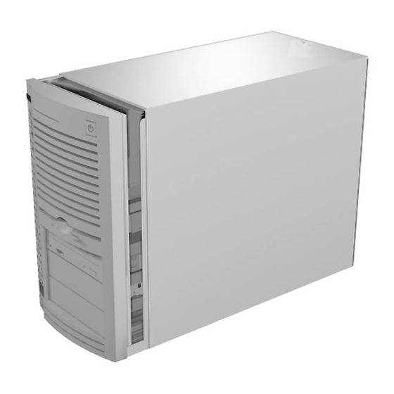
FRONT FEATURES The following figures show the features on the front of the desktop and minitower systems. A brief description follows the figures. Front features — desktop models 1-2 Introducing Your Computer... - Page 17 The following figure shows the system controls and lamps called out in the previous figure. System controls and lamps — desktop models Introducing Your Computer 1-3...
- Page 18 Front features — minitower models The following figure shows in detail the system controls and lamps called out in the previous figure. 1-4 Introducing Your Computer...
-
Page 19: System Controls And Lamps
System controls and lamps — minitower models System Controls and Lamps System controls let you select specific system operations. Lamps let you know the status of system operation. Your computer has the following controls and lamps: Power button Press this button to turn on system power. Press it again to turn off the power. - Page 20 Reset button The reset button lets you manually restart your system when it does not respond to keyboard commands. CAUTION Resetting your system can result in the loss of data. Press the reset button only when all other methods of restarting your computer fail. Power lamp The power lamp indicates whether system power is on or off.
-
Page 21: Ir Window
IR Window The IR (infrared) window is the system’s IR port. The IR port supports two-way wireless communications. The interface uses infrared as the transmission medium instead of a traditional cable. The IR port lets you transfer files to or from portable devices such as laptops and personal digital assistant (PDA) products using application software supporting IrDA data ®... - Page 22 Diskette drive A features — minitower models Your diskette drive has the following features: Diskette drive busy lamp Lights when your diskette drive is reading to or writing from a diskette. CAUTION To prevent damage to your diskette drive and data, do not turn off the system or remove a diskette while the diskette drive busy lamp is lit.
-
Page 23: Cd-Rom Reader
CD-ROM Reader A sixteen-speed CD-ROM reader is a standard feature in multimedia models. The CD-ROM reader is assigned as drive F. Use the CD-ROM reader to load and start programs from a compact disc (CD). You can also use the CD-ROM reader to play your audio CDs. - Page 24 CD-ROM reader features The CD-ROM reader has the following features: Headphone jack Allows the connection of an optional set of headphones with a stereo mini-jack plug. Volume control knob Lets you adjust the volume of an optional set of headphones. Open/close button Opens or closes the reader’s loading tray.
-
Page 25: Back Features
CD busy lamp Lights when the reader is retrieving data, music, or graphics/audio from a CD. Do not eject the CD or turn off the system unit when the lamp is on. CD tray Provides a surface for loading a CD into the reader. Press the open/close button to open or close the CD tray. - Page 26 The following figure shows these features in the desktop model. Rear features — desktop models 1-12 Introducing Your Computer...
- Page 27 The following figure identifies the audio connectors called out previously. Audio connectors — desktop models Introducing Your Computer 1-13...
- Page 28 The following figure shows the connectors from the rear of the minitower model. Rear features — minitower models The following figure identifies the audio connectors that were called out previously. 1-14 Introducing Your Computer...
-
Page 29: External Connectors
Your system has the following external connectors: VGA monitor connector Attach the signal cable from your monitor to this ® connector. Supports an NEC MultiSync monitor or other video graphics array (VGA)-compatible monitor with a 15-pin connector. Audio connectors These connectors come integrated on multimedia models. - Page 30 The microphone in jack lets you connect a microphone for recording audio information in your data system files. The line out jack allows you to connect an amplified output device such as powered speakers, stereo tape recorder, or an external amplifier for audio output. Use this jack to connect the stereo speakers that come with your system.
-
Page 31: Power Supply Features
Universal Serial Bus Ports The two Universal Serial Bus (USB) ports allows you to add new plug and play serial devices without opening up the system. You simply plug the devices into the ports. The USB determines system resources for each peripheral and assigns them without user intervention. -
Page 32: Speakers
SPEAKERS Multimedia models come with a pair of high-quality, 20-watt stereo speakers that you can arrange to suit your work environment. Speaker An AC adapter comes with the system. Set up the speakers with the AC adapter. The speakers connect to the line out jack on the back of the system unit. -
Page 33: Microphone
The sound software is Voyetra Multimedia Sound Software. See Chapter 6 for information on using the Voyetra sound software. MICROPHONE The microphone allows you to record voice and sound into your computer data files. See Chapter 6 for information on recording sound using the Voyetra sound software. -
Page 34: Getting Started
Getting Started This chapter provides the information you need to start using your system. Information includes: Using a Mouse If you are already familiar with using a mouse, skip this section. Using Online Documentation Read this section to use the comprehensive online system documentation about your computer. -
Page 35: Using Online Documentation
Double click Some actions require a double click to execute them. To “double click” an object, point to the object and press and release the left mouse button twice. Press Pressing the mouse button holds an action until you release the mouse button. Drag Dragging your mouse attaches your pointer to an object on the screen and allows you to highlight text or move... - Page 36 NEC PowerMate System Documentation icon. A welcome screen appears with the information you need to use the online documentation. The NEC PowerMate Series System Documentation is a comprehensive source of information about your system. To help you find the information you need, the documentation...
-
Page 37: Where To Go From Here
See the online help file, “Setting Up a Healthy Work Environment.” Take the System Tour in your online NEC PowerMate Series System Documentation. See the online User's Guide in your online NEC PowerMate Series System Documentation. -
Page 38: Quick Reference To Information About Your
Quick Reference to Information About Your Computer WHAT YOU WANT TO FIND WHERE TO FIND IT Basic information about my Online User's Guide in the NEC PowerMate computer Series System Documentation Setting a password “Setting a Password” in the online User's... - Page 39 WHAT YOU WANT TO FIND WHERE TO FIND IT Access to the World Wide Web “Microsoft Internet Explorer” in the online System Tour ( NEC PowerMate Series System Documentation ) Transferring files from my LapLink online help and “Using the IR Port” in...
-
Page 40: Installing Options
® VGA-compatible monitor such as NEC's MultiSync XE and XP series. SIMM memory your system comes with 16 or 32 MB of RAM upgradeable to 384 MB of 32- or 36-bit, 60 ns, high-speed memory using SIMM sticks. -
Page 41: Option Installation Procedures
processor upgrade a 320-pin zero insertion force (ZIF) socket on the system board supports the primary Pentium™ MMX™ processor or an OverDrive™ processor for upgrades. drives desktop systems support a total of four storage devices and minitower systems support a total of six storage devices. -
Page 42: Safety Precautions
Do not disassemble parts other than those specified in the procedure. All screws are Phillips-head unless otherwise specified. Label any removed connectors. Note where the connector goes and in what position it was installed. Safety Precautions Take care when working inside the system and when handling computer components. -
Page 43: Cover Removal And Replacement
Avoid carpets in cool, dry areas. Leave an option, such as a board or chip, in its anti-static packaging until ready to install it. Dissipate static electricity before handling any system components (boards, chips, and so on) by touching a grounded metal object, such as the system's unpainted metal chassis. -
Page 44: Removing The Desktop Cover
Removing the Desktop Cover The following procedure describes how to remove the desktop cover. WARNING Before removing the system unit cover, turn off the power and unplug the system power cable. Power is removed only when the power cable is unplugged. Turn off and unplug the system unit. - Page 45 Loosen the two captive thumb screws at the rear of the system unit. Removing cover screws From the rear of the system, grasp the sides and slide the cover about an inch away from the front. NOTE The cover fits tightly. Press the front edge of the cover to release it from the front panel.
- Page 46 Releasing the cover Lift the cover up and away from the system unit. Installing Options 3-7...
-
Page 47: Replacing The Desktop Cover
Replacing the Desktop Cover Replace the cover as follows. Align the tabs on the sides of the cover with the inside unit frame as you position the cover over the chassis. Replacing the system unit cover Slide the cover forward to meet the front panel. NOTE The cover fits tightly. -
Page 48: Removing The Minitower Cover
Reconnect all external peripherals. Plug in your power cables. Removing the Minitower Cover The following procedure describes how to remove the minitower cover. WARNING Before removing the system unit cover, turn off the power and unplug the system power cable. Power is removed only when the power cable is unplugged. - Page 49 Loosen the three thumb screws at the rear of the system unit. If you installed a padlock on the back of the system, unlock the padlock and remove it. Loosening minitower cover screws 3-10 Installing Options...
- Page 50 From the rear of the system, grasp the handle and pull it back so that the cover clears the padlock slot. Releasing the minitower cover Lift up at the top of the cover to release the cover tabs from the chassis. Pull the cover up until it comes free of the chassis.
-
Page 51: Replacing The Minitower Cover
Replacing the Minitower Cover Replace the minitower cover as follows. Insert the metal tabs on the top of the system cover into their slots on the chassis. Insert the metal tabs on the bottom of the system cover into their slots on the chassis. Replacing the minitower cover Slide the cover forward to meet the front panel. -
Page 52: Expansion Boards
NOTE The cover fits tightly. If the cover does not slide all the way to the front panel, place one hand on the front of the unit while you slide the cover forward from the rear. Secure the cover with the three thumb screws. (See “Removing the Minitower Cover.”) Reconnect all external peripherals. -
Page 53: Locating Expansion Slots
Locating Expansion Slots The desktop system has four useable expansion slots and the minitower system has five expansion slots. two ISA slots in both systems one PCI slot in the desktop, two PCI slots in the minitower system one shared PCI/ISA slot in both systems ISA expansion slots support industry-standard 8-bit or 16- bit expansion boards. -
Page 54: Installing An Expansion Board
Locating minitower expansion slots Installing an Expansion Board Install expansion boards in the system as follows. Remove the system unit cover. Follow any preinstallation instructions that come with the expansion board (such as setting switches or jumpers on the board). If installing a board in the inside expansion slot (next to the power supply) in the desktop system, see “Installing an Expansion Board in the Inside Slot.”... - Page 55 CAUTION A slot cover can damage the system board or any option board if it falls into the system. Take care to keep the slot cover from falling when removing the screw. If the slot cover does fall into the unit, remove it before replacing the cover.
- Page 56 Removing a minitower slot cover 5. Hold the board by its edges and insert it into the expansion slot (see the figure on the following page). Align full-size expansion boards with the guide rail at the front of the system unit. Press the board firmly into the expansion slot connector.
- Page 57 Installing an expansion board in the desktop Installing an expansion board in the minitower 3-18 Installing Options...
-
Page 58: Installing An Expansion Board In The Inside Slot
7. Attach any signal cables required by the expansion board. Replace the system unit cover. Installing an Expansion Board in the Inside Slot Use this procedure if installing an expansion board into the inside slot in your system. Remove the system unit cover. Follow any preinstallation instructions that comes with the expansion board (such as setting switches or jumpers on the board). - Page 59 Removing the slot cover support screws Hold the board by its edges, component side down and the bracket end facing the rear of the unit, and insert it into the expansion slot. Press the board firmly into the expansion slot connector. Gently rock the board from side-to-side to seat it into the connector.
-
Page 60: Removing An Expansion Board
Hold the slot cover support over the expansion board bracket and replace the two screws removed earlier. The slot cover support secures the expansion board in place. Attaching the slot cover support Attach any signal cables required by the expansion board. - Page 61 Remove the screw that secures the board to the support bracket. Removing the expansion board in the desktop 4. Pull the board out of the connector. Gently rock the board from side-to-side to release it from its connector. Removing the expansion board in the minitower 3-22 Installing Options...
-
Page 62: Removing An Expansion Board From The Inside Slot
Replace the slot cover removed when the expansion board was installed. Replace the system unit cover. Removing an Expansion Board from the Inside Slot Use this procedure if removing an expansion board from the inside slot in your system. Remove the system unit cover. Label and remove any cables from the expansion board. -
Page 63: System Board Options
Removing the slot cover screw Pull the board out of the connector. Gently rock the board from side-to-side to release it from the connector. Replace the system unit cover. SYSTEM BOARD OPTIONS Some of the options require locating the connector on the system board. -
Page 64: Simm Upgrade
System board sockets and connectors SIMM UPGRADE PowerMate P2166M/P2200M Series system configurations come with 16 or 32 MB of main system memory. Six sockets on the system board support up to 384 MB of high- speed memory using industry-standard, tin-plated, single in-line memory modules (SIMM). -
Page 65: Checking System Memory
8-MB by 32- or 36-bit (32-MB stick) 16 MB by 32- or 36-bit (64 MB stick). CAUTION To avoid corrosion between different metals, only use tin-plated SIMM sticks. Checking System Memory Use the following procedure to: check the memory installed in the system determine the SIMM configuration needed to increase memory NOTE... -
Page 66: Recommended Memory Upgrade Path
Recommended Memory Upgrade Path TOTAL BANK 0 BANK 1 BANK 2 MEMORY SIMM 1 SIMM 2 SIMM 3 SIMM 4 SIMM 5 SIMM 6 8 MB 4 MB 4 MB Empty Empty Empty Empty 16 MB 4 MB 4 MB 4 MB 4 MB Empty... -
Page 67: Removing A Simm
Recommended Memory Upgrade Path TOTAL BANK 0 BANK 1 BANK 2 MEMORY SIMM 1 SIMM 2 SIMM 3 SIMM 4 SIMM 5 SIMM 6 88 MB 32 MB 32 MB 8 MB 8 MB 4 MB 4 MB 96 MB 32 MB 32 MB 8 MB 8 MB... -
Page 68: Installing A Simm
Press the metal clips at the outer edges of the socket away from the SIMM. Push the SIMM away from the locking tabs and remove it from the socket. Removing a SIMM Use the following procedure to install a SIMM stick. Installing a SIMM Install a SIMM as follows. - Page 69 CAUTION Before installing a SIMM, reduce static discharge by touching the system's metal chassis. Install the SIMMs from the back to the front. Align the notched end of the SIMM with the left side of the SIMM socket as shown in the following figure. Insert the SIMM at an angle into the socket.
-
Page 70: Video Upgrade
VIDEO UPGRADE Upgrade your video memory by adding a 3-MB upgrade SGRAM module as follows. NOTE Your system comes standard with 2 MB of SGRAM and already includes a 1 MB upgrade module in addition to 1 MB mounted on the system board. - Page 71 Aligning the video SGRAM module with the sockets Replace any boards that were removed. Replace the system unit cover. 3-32 Installing Options...
-
Page 72: Overdrive Processor Upgrade
OVERDRIVE PROCESSOR UPGRADE The zero-insertion force (ZIF) socket accepts pin-grid-array (PGA) processors, such as the primary processor or an OverDrive processor. CAUTION Incorrect installation of the processor can damage the processor, system board, or both. Follow the installation instructions carefully. The system requires a heatsink on the OverDrive processor. - Page 73 Releasing the processor CAUTION Before picking up the processor, reduce static discharge by touching the metal frame of the system unit. Lift the processor out of the socket. Continue with the following procedure to install the new OverDrive processor. 3-34 Installing Options...
-
Page 74: Installing The Overdrive Processor
Installing the OverDrive Processor Remove the processor currently in the system (see previous procedure). CAUTION Before picking up the OverDrive processor, reduce static discharge by touching the metal frame of the system unit. Align the notched corner of the OverDrive processor with the alignment corner in the socket and insert the processor. -
Page 75: Data Storage Devices
CAUTION Remember to either reattach the heatsink used with the old processor or install the new heatsink supplied with the OverDrive processor. Check to see if the newly installed OverDrive processor requires a system board jumper change (see Chapter 5, Setting System Board Jumpers). -
Page 76: Locating Device Slots
Locating Device Slots The desktop system has four storage device slots and the minitower has six slots. (See the figures on the following pages): a 3 1/2-inch accessible device slot which contains the standard 1.44-MB diskette drive internal hard disk drive slots (1-inch high, thin-height) desktop: one 3 1/2-inch internal hard disk drive slot minitower: two 3 1/2-inch internal hard disk slots Hard disk configurations come with an IDE hard disk... - Page 77 The following figure shows the device slot locations. Locating desktop device slots Locating minitower device slots 3-38 Installing Options...
-
Page 78: Preparing The Device
Preparing the Device Before installing a storage device in the system, follow any preinstallation instructions that come with the device. For example, check the following: Diskette drive remove any termination on the optional diskette drive. See the documentation that comes with the drive. -
Page 79: Diskette Drive Signal Cable
System board cable connectors Diskette Drive Signal Cable A three-connector diskette drive signal cable comes attached to the system board and to the standard 1.44-MB diskette drive. The installation of a second diskette drive in your system does not require the replacement of the existing diskette drive signal cable. -
Page 80: Ide Signal Cables
The following figure shows a three-connector diskette drive signal cable. Optional diskette drive signal cable IDE Signal Cables Hard disk systems come with a three-connector IDE interface cable attached to the primary IDE connector. Multimedia systems come with a second IDE cable connected to the CD-ROM reader and to the secondary IDE connector. - Page 81 The following figure shows a typical three-connector IDE cable. If the IDE cable is not keyed with a connector tab, align the colored edge of the cable with the pin 1 side of the drive connector. Optional IDE cable connectors 3-42 Installing Options...
-
Page 82: System Power Cables
System Power Cables Power cables come from the power supply and are attached to the standard storage devices. System power cables vary in length and provide connector sizes to accommodate a variety of supported storage configurations. Power cable connectors are keyed to fit only in the correct position. The following figure shows the power cable connectors. -
Page 83: Ide Device Cabling
IDE Device Cabling The following procedure explains how to cable an IDE device. Connect the signal cable connector to the connector on the IDE device. Take care to prevent bending drive connector pins. Align the cable connector as shown in the following figure. Locate an available power connector coming from the power supply. -
Page 84: Diskette Drive Cabling
Diskette Drive Cabling Connect the diskette drive signal cable connector to the signal connector on the diskette drive as shown in the following figure. Locate an available power connector. Connect the power cable to the power connector on the device. Connecting 1.2-MB diskette drive cables Installing Options 3-45... -
Page 85: Installing Desktop Storage Devices
Installing Desktop Storage Devices The following subsections describe how to install 3 1/2-inch and 5 1/4-inch drives. The installation procedures include: removing the desktop 3 1/2-inch drive bracket installing a desktop 3 1/2-inch drive removing the desktop front panel installing a desktop 5 1/4-inch device replacing the desktop front panel replacing the desktop 3 1/2-inch drive bracket. -
Page 86: Installing The Desktop 3 1/2-Inch Drive
Removing the 3 1/2-inch drive bracket Installing the Desktop 3 1/2-Inch Drive Install the hard disk drive into the drive bracket as follows. Remove the system unit cover. Remove the 3 1/2-inch drive bracket from the system unit (see “Removing the Desktop 3 1/2-Inch Drive Bracket”). -
Page 87: Removing The Desktop Front Panel
Secure the device to the bracket with the four screws, two to a side, that come with the device. Securing a 3 1/2-inch drive Connect the drive cables. Replace the 3 1/2-inch drive bracket (see “Replacing the Desktop 3 1/2-Inch Drive Bracket”). Removing the Desktop Front Panel Remove the front panel only if you are installing a 5 1/4-inch device. - Page 88 Removing the desktop front panel Identify the slot for the device being installed. Remove the blank panel from the selected slot by pressing the panel tabs from inside the front panel and pushing the blank panel out. Installing Options 3-49...
-
Page 89: Installing The Desktop 5 1/4-Inch Device
Locating the blank panel tabs Remove the perforated metal plate from the selected slot on the chassis by pulling the metal plate back and forth until it releases. Install the device (see “Installing the Desktop 5 1/4-Inch Device”). Installing the Desktop 5 1/4-Inch Device Install an accessible device into the device cage as follows. - Page 90 NOTE If the device comes with drive rails, do not attach them. Remove any rails already attached. From the front of the system, insert the device, connector end first, into the device slot. NOTE To easily access device connectors for cabling, do not insert a 5 1/4-inch device all the way into the slot.
-
Page 91: Replacing The Desktop Front Panel
Replace the drive bracket (see “Replacing the Desktop 3 1/2-Inch Drive Bracket”). Replacing the Desktop Front Panel Replace the front panel only after it has been removed for a 5 1/4-inch device installation. If installing a 5 1/4-inch device, see “Installing the Desktop 5 1/4-Inch Device.” Align the four front panel tabs with the holes in the front of the system unit. -
Page 92: Replacing The Desktop 3 1/2-Inch Drive Bracket
Replacing the Desktop 3 1/2-Inch Drive Bracket When replacing the 3 1/2-inch drive bracket, take care to prevent pulling and loosening the cable connections. Place the 3 1/2-inch drive bracket in the 3 1/2-inch device slot. Slide the 3 1/2-inch drive bracket toward the front of the chassis so that the tabs secure the bracket. -
Page 93: Installing Minitower Storage Devices
Installing Minitower Storage Devices The following subsections describe how to install 3 1/2-inch and 5 1/4-inch drives. The installation procedures include: installing the minitower 3 1/2-inch drive removing the minitower side panel removing the minitower front panel installing a minitower 5 1/4-inch device replacing the minitower front and side panels Installing the Minitower 3 1/2-Inch Drive Install the hard disk drive into the rear slot as follows. - Page 94 To install the internal hard disk drive, you must first remove the power supply. Remove the power supply as follows. Locate the power supply as shown. Locating the power supply Disconnect the power supply cables from the system board. Installing Options 3-55...
- Page 95 Remove the power supply screws. Removing the power supply Lift the power supply out of the system unit. Align the holes in the hard disk drive with the holes at the bottom of the unit. 3-56 Installing Options...
-
Page 96: Removing The Minitower Side Panel
Secure the device to the bottom of the system unit. Securing the 3 1/2-inch drive Connect the drive cables. Replace the power supply and reattach the power supply cables to the system board. Replace the four screws. Replace the system unit cover. See “Replacing the Minitower Cover.”... - Page 97 If you are installing a 3 1/2-inch hard disk drive (see “Installing the 3 1/2-Inch Drive”). Remove the system unit cover as previously described. Remove the side panel by removing the two screws from the top of the panel. Removing the minitower side panel 3-58 Installing Options...
-
Page 98: Removing The Minitower Front Panel
Removing the Minitower Front Panel Remove the front panel only if you are installing a 5 1/4-inch device. The front panel does not need to be removed if you are installing a 3 1/2-inch hard disk drive. Remove the front panel by releasing the six tabs from the back of the front panel. -
Page 99: Installing The Minitower 5 1/4-Inch Device
Remove the slot cover from the selected slot on the chassis. Removing the slot cover Install the device (see the following section “Installing the Minitower 5 1/4-Inch device”). Installing the Minitower 5 1/4-Inch Device Install an accessible device into the device cage as follows. Follow the preinstallation instructions that come with the device, such as setting jumpers and switches. - Page 100 Attaching device rails From the front of the system, insert the device, connector end first, into the device slot. NOTE To easily access device connectors for cabling, do not insert a 5 1/4-inch device all the way into the slot. Connect the device cables.
-
Page 101: Replacing The Minitower Side And Front Panels
Securing the device Replacing the Minitower Side and Front Panels To replace the front and side panels, follow this procedure. Align the four front panel tabs with the holes in the front of the system unit. Evenly press the front panel into position until the tabs lock the panel in place. - Page 102 Aligning the front panel Replace the side panel, and reinsert the screws to hold the panel in place. Replace the cover. See “Replacing the Minitower Cover.” Run the Setup program to set the new configuration. Installing Options 3-63...
-
Page 103: Adding External Options
ADDING EXTERNAL OPTIONS This subsection includes installation procedures for the following external options: parallel printer serial devices. Connecting a Parallel Printer NOTE Before connecting a printer to the system, be sure the printer is set up correctly. Follow the setup instructions that come with the printer. - Page 104 Connecting a printer cable to the desktop Connecting a printer cable to the minitower Installing Options 3-65...
-
Page 105: Connecting An Rs-232C Device
Secure the cable with the screws provided. Connect the other end to the printer. Connecting an RS-232C Device NOTE Before connecting a serial device to the system, be sure the serial device is set up correctly. Follow the setup instructions that come with the option. - Page 106 Connecting an RS-232C cable to the minitower Secure the cable with the screws provided. Connect the other end to the serial device. Installing Options 3-67...
-
Page 107: Setting System Parameters
Setting System Parameters This chapter provides information on the NECCSD utilities that ship with your system. The following topics are covered in this chapter. Setup utility Flash utility LANDesk Client Manager CD Restore utility THE SETUP UTILITY The Setup utility program allows you to enter system configuration information and control special features of the system. -
Page 108: When To Use Setup
System configuration information is stored in nonvolatile memory. A nonvolatile memory device retains its data when system power is turned off. Nonvolatile memory in your system is a complementary metal-oxide semiconductor (CMOS) chip backed up by a battery on the system board. The battery supplies continuous power to CMOS memory and maintains configuration information when system power is off (see “Replacing the CMOS Battery ”... -
Page 109: How To Start Setup
configure system connections for peripherals such as your diskette drive, hard disks, and devices connected to the printer port and serial ports. customize your system with security features such as passwords, diskette drive restriction, virus check reminder and system backup reminder. set system parameters in the event that you need to replace the complimentary metal oxide semiconductor (CMOS) battery. -
Page 110: How To Use Setup
Main Advanced Security Exit System Date June 26 1996 Help System Time 08:12:20 Back Enter Select Floppy Options Press Enter Primary IDE Master IBM-DAQA-32160 Previous Item Primary IDE Slave Not Installed Next Item Secondary IDE Master Not-Installed Select Menu Secondary IDE Slave Not-Installed Language English (US) -
Page 111: Main Menu
Navigation Keys Function Selects next menu. arrow keys Loads the Default Configuration values for this menu. Selects the Previous Value for the field. Save and Exit To display a submenu, use the arrow keys to move the cursor to the submenu you want. Then press Enter MAIN MENU The following is a list of available options when you select... -
Page 112: System Date/Time
Video Mode Mouse Base Memory Extended Memory BIOS Version System Date/Time Use this menu to set the current time and date. The settings remain in memory even after you turn off the system power. To set the date, enter the current month, day, and year in mm/dd/yyyy format. -
Page 113: Ide Device Configuration Submenu
Jumper settings on the IDE device must be set to the master or slave device (see the documentation that comes with the device). IDE Device Configuration Submenu The IDE Device Submenu lets you check or change the following hard disk drive parameters. IDE Device Configuration Number of Cylinders Number of Heads... -
Page 114: Ide Translation Mode
IDE Translation Mode The IDE Translation Mode parameter controls the way in which the BIOS interacts with the drive in terms of drive geometry. Proper choice is dependent upon the drive’s size, capabilities, and the operating system (OS) used. The following choices are available. - Page 115 CAUTION When set to Auto Detected the BIOS will detect what the drive is capable of, not the translation mechanism which was used to format the drive. If a drive is run in a mode other than the mode in which partitioned formatted,...
-
Page 116: Language
Language The installed language will appear in the Setup and BIOS text strings. English (US) is the default in the U. S. and Canada. Boot Options When the cursor is placed in the Boot Option field, you can select it by pressing . -
Page 117: System Cache
System Cache The default for the System Cache field is “Enabled.” This field controls both the primary and secondary caches. Setting the system cache to “Disabled” will hurt performance, but might be required when running software which utilizes software timing loops and needs to be slowed down to execute properly. -
Page 118: Hard Disk Pre-Delay
Hard Disk Pre-Delay The Hard Disk Pre-Delay field causes the BIOS to wait a specified time before accessing the first hard disk drive. Setting a pre-delay provides the system with some time to identify any additional drives before the standard hard drive initializes. -
Page 119: Scan User Flash Area
750 msec 1000 msec Typematic Rate The Typematic Rate field controls the speed characters repeat when you hold down a keyboard key. The higher the number the faster the repeat. The delay times are as follows: 6 char/sec (default) 8 char/sec 10 char/sec 12 char/sec 15 char/sec... -
Page 120: Mouse
Mouse This field cannot be entered, it is an information field only. The system supports a PS/2 mouse. If the mouse is not installed the field will not be displayed. The default is “Installed.” Base Memory This field cannot be entered, it is an information field only. The system uses 640 KB of base memory. -
Page 121: Processor Type
CAUTION Setting items in this menu to incorrect values can cause your system to malfunction. Processor Type This field cannot be entered, it is an information field only. The processor is a Pentium processor that is backward compatible with 8086, 80286, I386, and Intel 486 processors. -
Page 122: Ide Interface (Primary And Secondary)
IDE Interface (Primary and Secondary) The Primary and Secondary IDE Interface fields enable the IDE interface connectors on the system board. These fields can be either “Auto Configured” detected or “Disabled.” The default is “Auto Configured.” Floppy Interface The Floppy Interface field enables the diskette drive interface connector on the system board. -
Page 123: Parallel Port Interface
Parallel Port Interface The parallel ports may be “Auto” detected or “Disabled.” The default is “Auto.” When “Auto” is selected, the first free LPT port is assigned regardless of what is selected. The parallel port address options are as follows. Disabled LPT3, 3BCh, IRQ7 LPT1, 378h, IRQ7... -
Page 124: Hardware Monitor Interface
Hardware Monitor Interface This option “Enables” or “Disables” the hardware monitor subsystem. The default is “Enabled.” PCI LAN Interface For network-ready systems, this option “Enables” or “Disables” the onboard LAN interface. The default is “Enabled.” Advanced Chipset Configuration When the cursor is placed in the Advanced Chipset Configuration field, you can select it by pressing Enter The Advanced Chipset Submenu appears allowing... -
Page 125: Base Memory Size
Base Memory Size The Base Memory Size field controls the mapping of addresses between “512 KB” and “640 KB.” The two choices are described as follows. 512 KB directs address mapping between 512 KB and 640 KB to the ISA bus. 640 KB (default) directs address mapping between 512 KB and 640 KB to the system DRAM. -
Page 126: Video Palette Snoop
Video Palette Snoop The Video Palette Snoop field enables card “snoop” (also called RAMDAC shadowing) write cycles to the ISA video card’s palette registers. This field can be either “Enabled” or “Disabled,” the default is “Disabled.” This should only be set to “Enabled” if all of the following conditions occur. -
Page 127: Power Management Submenu
Power Management Submenu The Power Management Submenu lets you check or change the Advanced Power Management parameter. Selecting the Advanced Power Management field enables or disables power management support in the BIOS. Power management reduces the amount of energy used after specified periods of inactivity. -
Page 128: Inactivity Timer (Minutes)
Inactivity Timer (Minutes) The Inactivity Timer (Minutes) field controls the number of minutes that the system will detect no user activity before going into low power mode. Minutes range between 0 and 255; the default value is 10 minutes. Hot Key The Hot Key field is used to define a key which, when entered, will cause the BIOS to put the OS into power management mode. -
Page 129: Plug And Play Configuration
Hot Key Parameters HOT KEY FUNCTION Powerdown Hot Key System powers down. Powers up Enabled Only when any key/mouse activity is detected. Security Hot Key System secure immediately. Enabled Only Keyboard lamps blink. Input accepted when password typed. Both Hot Keys System secure immediately. -
Page 130: Boot With Pnp Os
The choices are as follows. Use BIOS Setup The BIOS depends upon the information provided by run-time Plug and Play software (Configuration Managers and ICU). When “Use BIOS Setup” is chosen, the BIOS depends on run- time software to ensure that there are no conflicts between ISA boards with Plug and Play capabilities and those without. -
Page 131: Isa Shared Memory Base Address
When a value other than “Disabled” is selected, a block is unshadowed and the ISA Shared Memory Base Address field will appear. Disabled (default) 16 KB 32 KB 48 KB 64 KB 80 KB 96 KB NOTE If a value of “96 KB” is selected, then the ISA Shared Memory Base Address field can only be set to C8000h;... -
Page 132: Event Logging Configuration
Available interrupt requests (IRQ) between IRQ3 through IRQ15 will be displayed. Interrupts consumed by on-board resources will not be visible. NOTE All but one IRQ can be set to “Used By ISA Card.” One must remain available for a PCI expansion board. -
Page 133: Security Passwords
Security Passwords PASSWORD PASSWORD ACCESS ACCESS ENABLED AT BOOT SETUP ALL SETUP UNATTENDED SECURITY FIELDS START HOT KEY User Password Only Administrative Password Only Both User and No (User) Administrative Passwords Yes (Admin) No Passwords Enabled If the Administrative Password is in effect and Setup is entered with the User Password, only the following fields may be changed. -
Page 134: Set User Password And Set Administrative Password
The Security Submenu lets you check or change the following password parameters. NOTE If neither the User or Administrative Password is “Enabled,” the Unattended Start and Security Hot Key fields are not displayed. User Password This field allows you to enable a user level password during POST and to enter Setup. -
Page 135: Unattended Start
If there is already a User or Administrative Password, then a dialog box with the following prompts appears. Enter current password: [ Enter new password: [ Confirm new password: Unattended Start The Unattended Start field controls the point at which the User Password is required. -
Page 136: Exit Saving Changes
Exit Saving Changes Exit Discarding Changes Load Setup Defaults Discard Changes. Exit Saving Changes After making your selections on the Setup menus, always select “Exit Saving Changes” to make them operative. When “Exit Saving Changes,” has been selected, the program displays this message: Exit Saving Changes? Press Enter to Continue Press ESC to Abort... -
Page 137: Load Setup Defaults
Load Setup Defaults To load all the default Setup values in the Setup menus, select “Load Setup Defaults” from the Exit Submenu. Reloading the defaults does not affect the any set passwords. The program displays this message: Load Setup Defaults? Press Enter to Continue Press ESC to Abort To load the defaults shipped with the system press... -
Page 138: Flash Utility
Performing an update is done with a BIOS flash diskette. The diskette contains the latest version of the BIOS code. You can obtain the flash diskette from NEC Technologies or, if a modem is available, the latest BIOS can be downloaded from NEC’s Bulletin Board Service (BBS). -
Page 139: Landesk Client Manager
See NEC Bulletin Board Service for information about using the bulletin board (available in the U.S. and Canada). LANDESK CLIENT MANANGER LANDesk Client Manager is provided with your PowerMate system. With Client Manager you can review system inventory. view DMI-compliant component information. -
Page 140: Pc Health Meter
The monitoring is in real time so that if an unhealthy workstation is fixed, you can refresh the screen to view the new correct PC health. You can also set the monitor to report only unhealthy workstations. PC Health Meter The PC Health meter is a traffic signal that provides a visual indicator of workstation health. -
Page 141: Inventory
Once a threshold level has been passed on a workstation, you can request notification of the problem and have it written into a log file. Inventory Client Manager Inventory views the hardware and software components of your workstation. The inventory consists of the following categories: workstation summary basic hardware... -
Page 142: Using Dmi
Using DMI As a part of the LANDesk Client Manager, the Desktop Management Interface (DMI) is the standard interface used to manage system components on the computer. Examples of system components are network interface cards, printers, and software applications. System components provide a Management Information Format (MIF) file to be DMI compliant. -
Page 143: Cd Restore
Current readings are displayed for temperature, power supply voltages, and chassis state. Heceta interrupts can be detected when “out of range” conditions occur. User prompts are displayed to alert the user of a potentially harmful condition. CD RESTORE Your system ships with a CD Restore compact disc (CD) included. -
Page 144: System Recovery
System Recovery Use this option as a last resort when your preinstalled software becomes unusable or you can’t reboot from the hard disk. This option requires booting from the CD. The System Recovery option provides a full system recovery. This means you’ll be able to restore your system to its original factory- shipped state. -
Page 145: Restoring Individual Files
CD-ROM reader. On the Windows 95 desktop, double click “My Computer.” Double click the CD-ROM reader “(F:)” icon. The NEC System Restore screen appears. At the System Restore screen, click “OK” to restore individual files. A license agreement appears. -
Page 146: Selecting Files
Selecting Files Under “Select files to restore,” select your files as follows: From the left dialog box, highlight the directory that contains the files you want to restore. From the right dialog box, highlight the files you want to use: To restore all of the files listed, click “Select all of the above.”... -
Page 147: Restoring The Files
Cancel — click this option to cancel the restoration. This returns you to the NEC System Restore menu. To proceed with the restoration, click “Restore the files listed.” When the restoration is completed, a file restore message appears. - Page 148 Full System Recovery should only be used if the preinstalled software is unusable. If you are unsure about using this procedure, call the NEC Technical Support Center (TSC). TSC representatives will help you determine if this is your situation. See Chapter 7, “24-Hour Information Services...”...
- Page 149 Click “Continue” to proceed with the System Recovery. A license agreement appears. Read the license agreement and click “I agree” to continue. The Start System Recovery screen appears. The Start System Recovery screen states that all the files will be removed and that this process is irreversible. At the “Are you sure?”...
-
Page 150: Setting System Board Jumpers
Setting System Board Jumpers This chapter provides jumper setting information for configuring your system for a particular system requirement. Situations that require changing the jumper settings include the following: You are upgrading your processor. You have interrupted the Flash utility during a BIOS upgrade. -
Page 151: Changing Processor Jumper Settings
CHANGING PROCESSOR JUMPER SETTINGS The following procedure explains how to locate and change the jumper setting when you upgrade your processor. WARNING: The system power must be off before changing a jumper setting. Power off and unplug the system and any peripherals. Remove the system unit cover (see “Removing the Desktop Cover”... - Page 152 (see the following figure). Change the jumper setting by lifting the plastic block and placing it on the appropriate pins as shown in the following figure. NEC recommends using needle-nose pliers to move a jumper. Setting System Board Jumpers 5-3...
- Page 153 Microprocessor Speed J1K2 200-MHz Processor/66-MHz Bus Speed Jumper 5-6, 1-2 (C) Jumper 5-6, 1-2 (D) 166-MHz Processor/66-MHz Bus Speed Jumper 5-6, 1-2 (C) Jumper 5-6, 2-3 (D) 150-MHz Processor/60-MHz Bus Speed Jumper 4-5, 2-3 (C) Jumper 5-6, 2-3 (D) 133-MHz Processor/66-MHz Bus Speed Jumper 5-6, 1-2 (C) Jumper 4-5, 2-3 (D) Processor Voltage...
-
Page 154: Bios Recovery
CAUTION The wrong Processor Voltage (VR/VRE) jumper setting could damage the system board processor. Be sure Processor Voltage jumper is set correctly for your processor. Reinstall any removed expansion boards (see “Replacing Expansion Boards” in Chapter 3). Replace the system unit cover (see “Replacing the Desktop Cover”... - Page 155 Locate the BIOS Recovery jumper J6C2 on the system board (see the figure “Locating system configuration jumpers”). You may have to remove any installed expansion boards to access the jumpers (see “Removing Expansion Boards” in Chapter 3). Move the jumper block to the Recovery Mode pins. BIOS Recovery J6C2 Normal Operation (Default) Jumper 2-1...
-
Page 156: Clearing Cmos
Replace the system unit cover. Reconnect the system power cables and peripheral devices. Power on the system. Run Setup (see Chapter 4, Setting System Parameters). CLEARING CMOS If you want to return your system to the factory default settings, use the following procedure to clear CMOS to the default factory settings. - Page 157 Move the jumper block to the Clear position. CMOS Clear J1K2 Normal Operation (Default) Jumper 4-5 Clear Jumper 5-6 Clear CMOS Jumper Replace the system unit cover (see “Replacing the Desktop Cover” or “Replacing the Minitower Cover” in Chapter 3). Connect system power cables and monitor.
-
Page 158: Denying Access To Setup
DENYING ACCESS TO SETUP In special cases, you may want to deny the user access to the Setup utility. In this case you must change the jumper from its default position. Use the following procedure to change the jumper setting. Power off the system and unplug any peripherals. -
Page 159: Clearing Your Password
Setup Access J1K2 Access Allowed (Default) Jumper 1-2 Access Denied Jumper 2-3 Setup Access Jumper If you removed any expansion boards, replace them (see “Replacing Expansion Boards” in Chapter 3). Replace the system unit cover. Reconnect the system power cables and peripheral devices. Power on the system. - Page 160 Remove the system unit cover (see “Removing the Desktop Cover” or “Removing the Minitower Cover” in Chapter 3). Locate the Password Clear jumper J1K2 (A) on the system board (see the figure “Locating system configuration jumpers” earlier in the chapter). You may have to remove any installed expansion boards to access the jumpers (see “Removing Expansion Boards”...
-
Page 161: Pci Expansion Slots
Return the jumper block to the Password Enabled position. If you removed any expansion boards, replace them (see “Replacing Expansion Boards” in Chapter 3). Replace the system unit cover. Power on the system. Run Setup to set a new password (see Chapter 4, Setting System Parameters). - Page 162 Move the jumper to the number of PCI slots you want enabled. NOTE In minitower configurations, when the jumper is set for Two PCI Slots, the shared PCI/ISA slot functions only as an ISA slot. CAUTION Do not change the jumper from Two PCI Slots (Default) to Three PCI Slots in minitower network configurations.
-
Page 163: Computer
Replace the system unit cover (see “Replacing the Desktop Cover” or “Replacing the Minitower Cover” in Chapter 3). Connect system power cables and monitor. Power on the system. The system lets you boot your computer. 5-14 Setting System Board Jumpers... -
Page 164: Using Voyetra Sound Software
Using Voyetra Sound Software Your PowerMate multimedia configuration ships with ® Voyetra multimedia sound software. Use this software to adjust the volume of your speakers, record sound using a microphone, play, edit, and record .WAV files, play music on your CD-ROM, and record, play or edit Musical Instrument Digital Interface (MIDI) sequences and save them as .MID files. -
Page 165: Power Bar
Power Bar Audio Mixer CD Player WAV Player MIDI Player AudioStation main screen layout POWER BAR The Power Bar is the most important module because it controls the other modules. It rearranges, opens and closes each module, which are then removed from the screen. It quits AudioStation and activates Help. -
Page 166: Audio Mixer
The Power Bar buttons are explained as follows. Launches Help for each component. Launches or closes the Audio Mixer module. Launches or closes the MIDI Player module. Launches or closes the CD Player module. Launches or closes the WAV Player module. NOTE The online help gives detailed information on each module. -
Page 167: Adjusting The Sound Using Software
Adjusting the Sound Using Software With your sound software, you can control sound right from the windows desktop. You can adjust the volume, speaker balance, and more. From the Programs group — click on the Voyetra icon. From the Control Panel — click on the Sound icon. From the Windows 95 taskbar —... -
Page 168: Wav Player
WAV PLAYER The WAV Player records sound by turning incoming electrical signals into numbers and saves it in computer memory. To play back the sound, the software changes the data back into electrical signals that the audio equipment amplifies and directs to the speakers or headphones. The data format created by the WAV Player is called .WAV files which is compatible with Windows.The “tada”... -
Page 169: Playing Digital Audio Files
Playing Digital Audio Files Use the following procedure to load and play digital audio files. To play a .WAV or .VOC digital audio file you must first insert the files you wish to hear in the playlist. Once you have created a playlist, Press OK to close the playlist. - Page 170 To play MIDI files, follow these procedures. Click on the Playlist button to open the MIDI file playlist window. In the File section, select the files by highlighting the files you want and click on the Add button. This inserts the files into a playlist.
-
Page 171: 24-Hour Information Services
24-Hour Information Services NECCSD has made it easy for you to get information and help when you need it. We offer 24-hour information services via: ™ NEC’s FastFacts Service NECCSD’s Bulletin Board Service ® America Online Service ® CompuServe Online Service E-mail to NECCSD’s Technical Support Services... -
Page 172: Nec's Fastfacts Service
NEC’S FASTFACTS SERVICE NEC’s FastFacts service is a self-help, automated electronic information service for obtaining up-to-date product application notes, installation procedures, troubleshooting tips, data sheets, technical information bulletins, illustrated parts lists, part numbers, and other information about your system. Using a fax machine, you can obtain information from FastFacts 24 hours a day, 7 days a week. - Page 173 Order information from FastFacts as follows. If you would like instructions for using FastFacts, request document number 63233469 when prompted. Be sure that your fax machine or fax/modem is on. Have the document number ready for the document you want. At your touch-tone telephone, enter 800-366-0476 (U.S.
-
Page 174: Neccsd Bulletin Board Service
NECCSD BULLETIN BOARD SERVICE If you have access to a modem, the NECCSD Bulletin Board Service (BBS) can be used to provide you with the latest information on hardware and software. The BBS allows you to download files (video drivers, printer drivers, BIOS updates, etc.) for system enhancements and upgrades. - Page 175 Following the HyperTerminal instructions, enter the BBS phone number (508-635-4706). Your business phone system and/or location might require a 9 1 or 1 prefix. NOTE The first time that you use the BBS, you will be requested to provide information for a new user questionnaire.
-
Page 176: America Online Service
At the Go To menu, click Keyword. At the prompt, type either NECTECH or NEC, then either press or click on Go. Enter At the NEC menu, double-click on one of the following topics, then follow the prompts: About NEC Terms and Conditions News... -
Page 177: Compuserve Online Service
Use the following steps to access CompuServe and NECCSD’s online information services. Log onto CompuServe. At the opening screen, click on Service, type in NEC TECH at the prompt, and click OK. At the NEC menu, double-click on one of the following... -
Page 178: E-Mail/Fax Technical Support Service
Access NEC BBS Access CompuServe Information Services Exit. Exit anytime by double-clicking on the rectangle in the upper left corner of the screen. E-MAIL/FAX TECHNICAL SUPPORT SERVICE The NECCSD Technical Support Center offers technical support by E-mail over the Internet network if you have a modem. -
Page 179: Internet
Service. To access the World-Wide-Web NECCSD Home Page, enter the following Internet Uniform Resource Locator (URL) through your service: http://www.nec.com/ To access the NECCSD ftp Site, enter the following Internet ftp address through your service: ftp.nectech.com Once in the file menu, follow the prompts to choose and download the file(s) you want. -
Page 180: Neccsd Technical Support Services
NECCSD TECHNICAL SUPPORT SERVICES NECCSD also offers direct technical support through its Technical Support Center. (NECCSD technical support is for U.S. and Canadian customers only, international customers should check with their sales provider.) Direct assistance is available 24 hours a day, seven days a week. -
Page 181: Solving System Problems
Solving System Problems Your system has a built-in checking program that automatically tests its components when you turn the system unit power on. If there is a problem, the system displays an error message. If this happens, follow any instructions on the screen. If screen messages do not help or an error message does not appear, use the information in this chapter to determine and solve the problem. -
Page 182: Problem Checklist
PROBLEM CHECKLIST If you have problems, go through the following checklist for possible solutions. Is the power switch on for the computer and any connected peripherals (monitor, printer)? Check that all power switches are on. Is the computer and its peripherals connected to a working AC power outlet or surge protector? Check the outlet or surge protector by plugging a lamp into the outlet or surge protector. -
Page 183: Solutions To Common Problems
SOLUTIONS TO COMMON PROBLEMS See the following sections to match your problem area and view the possible causes and solutions. When trying to solve problems, you should note what the system was doing when the problem occurred and what you attempted to do to correct the problem. - Page 184 Run the Setup Utility and check the Boot parameter settings to verify that the initial boot parameter is set for hard drive C and not for a diskette drive. System performance appears sluggish Check that your system is set for optimal operation. See your operating system documentation.
-
Page 185: Diskette Drive Problems
Diskette Drive Problems Check the following problems to see the possible cause and solution. Diskette won't load Check that the diskette is being loaded correctly. Check that the system and monitor power lamps are on and the power-on screen appears. Check that the diskette is formatted. -
Page 186: Monitor Problems
Monitor Problems Check the following problems to see the possible cause and solution. Monitor screen is dark Check that the monitor power cable is connected to the monitor and a power outlet, the monitor signal cable is connected to the system, and the brightness and contrast controls are adjusted. -
Page 187: Keyboard/Mouse Problems
Keyboard/Mouse Problems Check the following problem to see the possible cause and solution. Image appears on screen but nothing happens when you use the mouse or keyboard Tighten the keyboard or mouse cable connection. If this does not help, turn off the system, wait five or more seconds, and turn on the system. -
Page 188: Speaker Problems
Check that the cable connecting from the rear of the CD-ROM drive to the system board CD audio connector is in place and secure. The CD-ROM does not play music CDs See “CD Player” in Chapter 6, for further information on playing music CDs. -
Page 189: Replacing The Cmos Battery
REPLACING THE CMOS BATTERY A 3-volt lithium battery in your computer maintains system configuration information. If your system fails to maintain system configuration information, replace it with an identically rated battery from the same manufacturer. CAUTION Removing the battery from the system board causes the computer to lose system configuration information. - Page 190 Locate the battery socket on the system board. You may have to remove any expansion boards in the way. NOTE This procedure is for system boards using the 3-volt lithium batter shown in the following figure. Locating the battery socket on the system board 8-10 Solving System Problems...
- Page 191 Carefully release the battery from the tabs on one side of the socket and slide the battery out. CAUTION To maintain a tight battery contact with the socket, do not over-bend the battery clip. Removing the battery Remove the battery and discard in accordance with the manufacturer’s instructions.
-
Page 192: Diagnostic Diskette
24-hour services for answers to your questions. (Some services require a modem or fax machine.) NEC’s FastFacts Service NECCSD’s Bulletin Board Service America Online Service CompuServe Online Service E-mail to NECCSD’s Technical Support Services... -
Page 193: Getting Help From Your Company
If you still need help, continue with the suggestions that follow. Getting Help From Your Company If you are in a company, the best source of help may be internal. Your company may have designated central support personnel to whom you can go when you have problems. -
Page 194: Neccsd Warranty/Non-Warranty Repair Service
NECCSD Warranty/Non-Warranty Repair Service NECCSD’s repair service is designed to support your warranty and non-warranty service activity. Before you call for repair service, see the previous sections in this chapter to determine if you can solve the problem yourself, within your company, through your dealer, or with the help of a technician from the NECCSD Technical Support Center. -
Page 195: Setting Up A Healthy Work Environment
Setting Up a Healthy Work Environment WARNING Prolonged or improper use of a computer workstation may pose a risk of serious injury. To reduce your risk of injury, set up and use your computer in the manner described in this appendix. Contact a doctor if you experience pain, tenderness, swelling, burning, cramping, stiffness, throbbing, weak- ness, soreness, tingling and/or numbness in the hands,... - Page 196 Although some studies have shown an association between increasing hours of keyboard use and the development of some musculoskeletal disorders, it is still unclear whether working at a computer causes such disorders. Some doctors believe that using the keyboard and mouse may aggravate existing musculoskeletal disorders.
-
Page 197: Arrange Your Equipment
ARRANGE YOUR EQUIPMENT Arrange your equipment so that you can work in a natural and relaxed position. Place items that you use frequently within easy reach. Adjust your workstation setup to the proper height (as described in this appendix) by lowering the table or stand that holds your computer equipment or raising the seat height of your chair. -
Page 198: Adjust Your Chair
ADJUST YOUR CHAIR Your chair should be adjustable and stable. Vary your posture throughout the day. Check the following: Keep your body in a relaxed yet upright position. The backrest of your chair should support the inward curve of your back. Use the entire seat and backrest to support your body. - Page 199 Your seat depth should allow your lower back to com- fortably contact the backrest. Make sure that the backs of your lower legs do not press against the front of the chair. Extend your lower legs slightly so that the angle between your thighs and lower legs is 90°...
-
Page 200: Adjust Your Input Devices
ADJUST YOUR INPUT DEVICES Follow these points in positioning your keyboard and mouse. Position your keyboard directly in front of you. Avoid reaching when using your keyboard or mouse. If you use a mouse, position it at the same height as the keyboard and next to the keyboard. - Page 201 Type with your hands and wrists floating above the key- board. Use a wrist pad only to rest your wrists between typing. Avoid resting your wrists on sharp edges. Type with your wrists straight. Instead of twisting your wrists sideways to press hard-to-reach keys, move your whole arm.
-
Page 202: Adjust Your Monitor
ADJUST YOUR MONITOR Correct placement and adjustment of the monitor can reduce eye, shoulder, and neck fatigue. Check the following when you position the monitor. Adjust the monitor height so that the top of the screen is at or slightly below eye level. Your eyes should look slightly downward when viewing the middle of the screen. - Page 203 Rest your eyes periodically by focusing on an object at least 20 feet away. Blink often. Position the monitor at a 90° angle to windows and other light sources to minimize glare and reflections. Adjust the monitor tilt so that ceiling lights do not reflect on your screen.
-
Page 204: Vary Your Workday
VARY YOUR WORKDAY If you use your computer for prolonged periods, follow these instructions. Vary your tasks throughout the day. Take frequent short breaks that involve walking, stand- ing, and stretching. During these breaks, stretch muscles and joints that were in one position for an extended period of time. -
Page 205: Pre-Existing Conditions And Psychosocial Factors
Use a timer or reminder software to remind you to take breaks. To enhance blood circulation, alter your sitting posture periodically and keep your hands and wrists warm. NOTE For more information on workstation setup, see the American National Standard for Human Factors Engineering of Visual Display Terminal Workstations. -
Page 206: Checking Your Comfort: How Do You Measure Up
CHECKING YOUR COMFORT: HOW DO YOU MEASURE UP? Use this checklist to see if you are setting up your work environment to fit your physical needs. Checking Your Chair Do you sit in an upright position with the backrest sup- porting your lower back? When sitting, are your feet flat on the floor? Do you periodically adjust your chair and your posture? -
Page 207: Checking You
Checking You Is your work area set up to promote a natural and relax- ing working position with frequently used work items within close reach? Do you take frequent short breaks? Do you stretch and walk during your breaks? Do you vary your tasks during the day? Do you have regular eye checkups? Do you contact your doctor if you feel any sustained discomfort? -
Page 208: Limited Warranty
Limited Warranty NEC Computer Systems Division, Packard Bell NEC, Inc. (hereinafter “NECCSD”) warrants this Product to be free from defects in material and workmanship under the following terms: HOW LONG IS THE WARRANTY? Labor and parts are warranted for three (3) years from the date of the first consumer purchase in the U.S.A., Canada,... -
Page 209: What We Will Pay For And What We Will Not Pay For
Damage, deterioration or malfunction resulting from, but not limited to: Accident, misuse, abuse, neglect, fire, water, lightning or other acts of nature, unauthorized Product modification, or failure to follow instructions supplied with the product. Repair or attempted repair by anyone not authorized by NECCSD. -
Page 210: How You Can Get Warranty Service
HOW YOU CAN GET WARRANTY SERVICE Year One For the first year, NECCSD provides an on-site limited warranty for all PowerMate Series Computers installed within a 50-mile radius of a NECCSD TotalService Preferred Dealer location or NECCSD authorized third party maintenance organization. Such on-site warranty service may be obtained by contacting your local NECCSD TotalService Preferred Dealer or calling 1-800-632-4525. -
Page 211: Limitation Of Damages And Implied Warranties
LIMITATION OF DAMAGES AND IMPLIED WARRANTIES NECCSD'S SOLE LIABILITY FOR ANY DEFECTIVE PRODUCT IS LIMITED TO THE REPAIR OR REPLACEMENT OF THE PRODUCT AT OUR OPTION. NECCSD SHALL NOT BE LIABLE FOR: DAMAGE TO OTHER PROPERTY CAUSED BY ANY DEFECTS IN THIS PRODUCT, DAMAGES BASED UPON INCONVENIENCE, LOSS OF USE OF THE PRODUCT, LOSS OF TIME OR DATA, COMMERCIAL LOSS;... -
Page 212: For Information, Telephone 1-800-632-4525
FOR INFORMATION, TELEPHONE 1-800-632-4525 NOTE: All Products returned to NECCSD for service MUST have prior approval; this may be obtained by calling the above number. NECCSD Products are warranted in accordance with the terms of the applicable NECCSD limited warranty. Product performance is affected by system configuration, software, the application, customer data, and operator control of the system, among other factors. -
Page 213: C Reviewing System Interrupts
Reviewing System Interrupts The interrupt controller accepts requests from peripherals, issues interrupt requests to the processor, resolves interrupt priorities, and provides vectors for the processor to determine which interrupt routine to execute. The interrupt controller has priority assignment modes that can be reconfigured at any time during system operations. - Page 214 Interrupt Level Assignments INTERRUPT PRIORITY INTERRUPT DEVICE IRQ08 Real-time clock IRQ09 Available IRQ10 Available (Audio on multimedia configurations) IRQ11 Available IRQ12 PS/2 mouse IRQ13 Coprocessor IRQ14 Primary IDE IRQ15 Secondary IDE C-2 Reviewing System Interrupts...
- Page 215 Index Checking hard disk drive parameters, Accessing Voyetra from Windows 95, 6-1 Clearing password jumper, 5-10 Activating a module, 6-3 CMOS Adjusting sound, 6-4 battery replacement, 8-9 Advanced menu, 4-14 CMOS jumper, 5-7 America Online, 7-6 CompuServe, 7-8 Audio connectors, 1-15 Configuration Audio Mixer, 6-3 jumpers, 5-2...
- Page 216 3-66 Internet, 7-9 NECCSD bulletin board service, FastFacts service, 7-2 NECCSD technical support, 7- Fax support, 7-8 Features NEC's FastFacts, 7-2 back, 1-11–1-18 NECCSD's ftp site, 7-9 CD-ROM reader, 1-9 NECCSD's World Wide Web diskette drive, 1-8 home page, 7-9 front, 1-2–1-11...
- Page 217 Multimedia Sound Software package, 6-1 Keyboard connecting, 1-16 port, 1-16 NECCSD Bulletin Board Service, NEC Information group, 2-3 Lamps NECCSD repair service, 8-14 CD busy, 1-11 NECCSD Technical Support disk, 1-6 Center, 8-13 diskette drive busy, 1-8 NECCSD Technical Support...
- Page 218 Parallel port, 1-16 Record digital audio files, 6-5 Password Repair service, 8-14 changing entries, 4-28 Reset button, 1-6 setting, 4-26 Restarting your computer, 1-6 PC health indicator, 4-33 Restoring individual files, 4-39 PC Health meter, 4-34 Restoring system software PCI slot jumpers, 5-13 restore individual files, Peripheral submenu, 4-15 4-39–4-41...
- Page 219 Suspend button, 1-5 Warranty repair service, 8-14 mode, 1-5, 1-6 WAV, 6-5 System board interrupt controller, C-1 jumpers, 5-2 System recovery, 4-38, 4-41, 4-43 System restore options, 4-37 Technical support, 7-10 Troubleshooting, 8-1 common problems, 8-3 if you have a problem, 8-1 minor problems, 8-2 NECCSD Technical Support Center, 8-13...
- Page 220 (For United States Use Only) FEDERAL COMMUNICATIONS COMMISSION RADIO FREQUENCY INTERFERENCE STATEMENT WARNING: Changes or modifications to this unit not expressly approved by the party responsible for compliance could void the user’s authority to operate the equipment. NOTE: This equipment has been tested and found to comply with the limits for a Class B digital device, pursuant to Part 15 of the FCC Rules.
- Page 221 BATTERY REPLACEMENT A lithium battery in some computers maintains system configuration information. In the event that the battery fails to maintain system configuration information, NECCSD recommends that you replace the battery. See “Replacing the CMOS Battery” in Chapter 8 of this guide for battery replacement information. WARNING: There is a danger of explosion if the battery is incorrectly replaced.