Sharp KB3300JK - Insight Range With Microwave Drawer Service Manual
Free standing range with microwave drawer
Hide thumbs
Also See for KB3300JK - Insight Range With Microwave Drawer:
- Operation manual (32 pages) ,
- Overview (6 pages) ,
- Installation manual (8 pages)
Table of Contents
Advertisement
In the interest of user-safety the unit should be restored to its original condition and only parts identical to those specified
should be used.
WARNING TO SERVICE PERSONNEL:
This service manual is intended for use by persons having electrical and mechanical training and a level of
knowledge of these subjects generally considered acceptable in the appliance repair trade. Sharp Electronics
Corporation cannot be responsible, nor assume any liability, for injury or damage of any kind arising from the
use of this manual.
Microwave ovens contain circuitry capable of producing very high voltage and current. Contact with the
following parts may result in a severe, possibly fatal, electrical shock. (High Voltage Capacitor, High Voltage
Power Transformer, High Voltage Rectifier and Heat sink etc., and Magnetron, High Voltage Harness etc..)
BEFORE SERVICING ...................................................................................................... INSIDE FRONT COVER
WARNING TO SERVICE PERSONNEL ............................................................................................................... 1
MICROWAVE MEASUREMENT PROCEDURE .....................................................................................................3
FOREWORD AND WARNING ................................................................................................................................5
PRODUCT SPECIFICATIONS ............................................................................................................................... 6
POWER CONNECTION .........................................................................................................................................8
ANTI-TIP DEVICE ............................................................................................................................................... 10
CONTROL LAYOUT ............................................................................................................................................ 11
SCHEMATICS ..................................................................................................................................................... 12
TEST PROCEDURES .......................................................................................................................................... 17
TOUCH CONTROL PANEL ASSEMBLY ............................................................................................................. 28
OVEN/MICROWAVE DRAWER DISASSEMBLY ................................................................................................. 38
WIRING DIAGRAMS ........................................................................................................................................... 47
PRINTED WIRING BOARDS ............................................................................................................................... 53
PARTS LIST ........................................................................................................................................................ 58
PACKING AND ACCESSORIES ......................................................................................................................... 69
SHARP ELECTRONICS CORPORATION
This document has been published to be used for after sales service only. The contents are subject to change without notice.
SERVICE MANUAL
FREE STANDING RANGE
WITH MICROWAVE DRAWER
MODELS
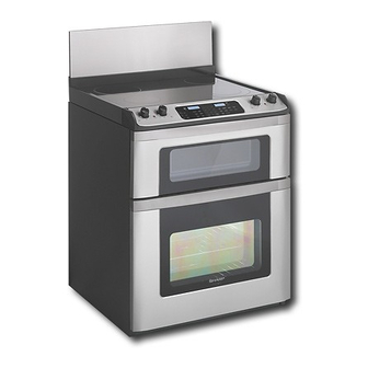
KB-3300JS pictured
TABLE OF CONTENTS
1
KB-3300JS
KB-3300JK
KB-3300JW
KB-3300JS
KB-3300JK
KB-3300JW
S74R243KB330J
Page
Advertisement
Table of Contents

Related Manuals for Sharp KB3300JK - Insight Range With Microwave Drawer


Summary of Contents for Sharp KB3300JK - Insight Range With Microwave Drawer
-
Page 1: Table Of Contents
This service manual is intended for use by persons having electrical and mechanical training and a level of knowledge of these subjects generally considered acceptable in the appliance repair trade. Sharp Electronics Corporation cannot be responsible, nor assume any liability, for injury or damage of any kind arising from the use of this manual. -
Page 2: Precautions To Be Observed Before And During Servicing To Avoid Possible Exposure To Excessive Microwave Energy
Before servicing an operative unit, perform a microwave emission check as per the Microwave Measure- ment Procedure outlined in this service manual. If microwave emissions level is in excess of the specified limit, contact SHARP ELECTRONICS CORPORATION immediately @1-800-237-4277. If the unit operates with the door open, service person should 1) tell the user not to operate the oven and 2) contact SHARP ELECTRONICS CORPORATION and Food and Drug Administration's Center for Devices and Radiological Health immediately. -
Page 3: Warning To Service Personnel
KB-3300JS KB-3300JK KB-3300JW WARNING TO SERVICE PERSONNEL Range units contain circuitry capable of producing very high voltage and current, contact with following parts may result in a severe, possibly fatal, electrical shock. (Example) High Voltage Capacitor, High Voltage Power Transformer, Magnetron, High Voltage Rectifier Assembly, High Voltage Harness, Heating Elements, etc.. -
Page 4: Safe Servicing Practices
6. Prior to returning the product to service, ensure that: • All electrical connections are correct and secure • All electrical leads are properly dressed and secured away from sharp edges, high-temperature components, and moving parts • All non-insulated electrical terminals, connectors, heaters, etc. are adequately spaced away from all metal parts and panels •... -
Page 5: Microwave Measurement Procedure
KB-3300JS KB-3300JK KB-3300JW MICROWAVE MEASUREMENT PROCEDURE A. Requirements: 1) Microwave leakage limit (Power density limit): The power density of microwave radiation emitted by a microwave oven should not exceed 1mW/cm at any point 5cm or more from the external surface of the oven, measured prior to acquisition by a purchaser, and thereafter (through the useful life of the oven), 5 mW/cm at any point 5cm or more from the external surface of the oven. - Page 6 KB-3300JS KB-3300JK KB-3300JW NOTES...
-
Page 7: Foreword And Warning
KB-3300JS ANTI-TIP DEVICE KB-3300JK / KB-3300JW FOREWORD SCHEMATICS This Manual has been prepared to provide Sharp Electronics Corp. Service Personnel and Service Information for the SHARP FREE STANDING RANGE WITH MICROWAVE DRAWER, KB-3300JS, KB-3300JK, and KB-3300JW. TEST PROCEDURE It is recommended that service personnel carefully study the entire text of this manual so that they will be qualified to render satisfactory customer service. -
Page 8: Product Specifications
KB-3300JS KB-3300JK KB-3300JW OVEN SPECIFICATION ITEM DESCRIPTION Power Requirements 120 /208 - 120/240Volts / 46/50 Amperes 60 Hertz Single phase, 3 wire grounded Thermal Oven Heating Elemants Top - 3000W Bottom - 2000W Case Dimensions Width 29-7/8" Height 37-5/16" Depth 27-5/16 Cooking Cavity Dimensions Width 22-5/8"... - Page 9 KB-3300JS KB-3300JK KB-3300JW MICROWAVE DRAWER SPECIFICATION ITEM DESCRIPTION Power Output 1000 watts (IEC TEST PROCEDURE) Operating frequency of 2450MHz Cooking Cavity Dimensions Width 17-11/32 Height 5-7/16" 1.0 Cubic Feet Depth 17-1/8" Control Complement Touch Control System Clock ( 1:00 - 12:59 ) Timer (0 - 99 min.
-
Page 10: Power Connection
KB-3300JS KB-3300JK KB-3300JW POWER CONNECTION 208/240 VOLT CONNECTION INSTRUCTIONS ACCESS TO TERMINAL BLOCK The range can be set for 208V or 240V. The voltage setting for your Loosen screw on rear access cover and pull down as illustrated in range is pre-set at 240V from the factory. Follow these steps to Figure 6 to access terminal block wiring connection. - Page 11 KB-3300JS KB-3300JK KB-3300JW 3 Make sure all connections are tightened securely and replace connections. Tighten all 3 or 4-wire leads to the terminal block. the rear access cover. See Figure 7. Follow wire locations shown in Figure 10. IMPORTANT DO NOT LOOSEN the factory installed nut GROUNDING INSTRUCTIONS- ONLY 3-WIRE CONNECTIONS: connections which secure the range wiring to the terminal A ground strap is installed on this range which connects the center...
-
Page 12: Anti-Tip Device
KB-3300JS KB-3300JK KB-3300JW DRILL PILOT HOLES AND FASTEN BRACKET ANTI-TIP DEVICE Drill a -inch pilot hole where screws are to be located. If bracket is to be mounted to the wall, drill pilot hole at an approximate 20 NORMAL INSTALLATION STEPS degree downward angle. -
Page 13: Control Layout
KB-3300JS KB-3300JK KB-3300JW CONTROL LAYOUT H O T S U R F A C E I N D I C A T O R L I G H T S C O N T R O L C O N T R O L K N O B S K N O B S C O N T R O L P A N E L... -
Page 14: Schematics
KB-3300JS KB-3300JK KB-3300JW Schematic-Off Condition... - Page 15 KB-3300JS KB-3300JK On condition (Bake & Microwave) KB-3300JW On condition (Broil & Microwave)
- Page 16 KB-3300JS KB-3300JK COOK TOP SCHEMATIC (DETAIL) KB-3300JW...
- Page 17 KB-3300JS KB-3300JK KB-3300JW MICROWAVE DRAWER SCHEMATIC (DETAIL)
- Page 18 KB-3300JS KB-3300JK KB-3300JW RANGE SCHEMATIC (DETAIL)
-
Page 19: Test Procedures
KB-3300JS KB-3300JK TEST PROCEDURES KB-3300JW PROCEDURE COMPONENT TEST LETTER TOUCH CONTROL PANEL ASSEMBLY TEST The touch control panel consists of circuits including semiconductors such as LSI, ICs, etc. Therefore, unlike conventional microwave ovens, proper maintenance cannot be performed with only a voltmeter and ohmmeter. - Page 20 KB-3300JS KB-3300JK TEST PROCEDURES KB-3300JW PROCEDURE COMPONENT TEST LETTER 4) Reconnect all leads removed from components during testing. 5) Re-install the covers. 6) Reconnect the power supply cord after the covers are installed. 7) Run the oven and check all functions. KEYBOARD GLASS UNIT TEST 1.
- Page 21 KB-3300JS KB-3300JK TEST PROCEDURES KB-3300JW PROCEDURE COMPONENT TEST LETTER 8.Disconnect the power supply cord, and then remove covers. 9.Open the drawer and block it open. 10.Discharge high voltage capacitor. 11.Reconnect all leads removed from components during testing. 12.Re-install the covers. 13.Reconnect the power supply cord after the covers are installed.
- Page 22 KB-3300JS KB-3300JK TEST PROCEDURES KB-3300JW PROCEDURE COMPONENT TEST LETTER 9) Disconnect the power supply cord, and then remove the covers. 10) Open the drawer and block it open. 11) Discharge high voltage capacitor. 12) Reconnect all leads removed from components during testing. 13) Re-install the covers.
- Page 23 KB-3300JS KB-3300JK KB-3300JW TEST PROCEDURES PROCEDURE COMPONENT TEST LETTER 9-2. Place the container on the center of tray in the oven cavity. 9-3. Close the door. 9-4. Touch the TIMER/CLOCK pad once, the POWER LEVEL pad twice and the START pad once. And touch the number pads 1 once and the number pad 4 once.
- Page 24 KB-3300JS KB-3300JK TEST PROCEDURES KB-3300JW PROCEDURE COMPONENT TEST LETTER SURFACE ELEMENT CONTROL SYSTEMS Di al Posit ion Contacts LO-MED Two types of surface elements control systems are L1 - P covered in this manual. L1 - H 1 Standard infinite switch. L2 - H 2 X - C Dual infinite switch.
- Page 25 KB-3300JS KB-3300JK TEST PROCEDURES KB-3300JW PROCEDURE COMPONENT TEST LETTER between the switch and the element are open. If the meter reads line to line voltage the element is defective. Element does not cycle: If the element does not cycle when the switch is set in a position other than high the switch is defective.
- Page 26 KB-3300JS KB-3300JK TEST PROCEDURES KB-3300JW PROCEDURE COMPONENT TEST LETTER Both elements do not heat: With the switch turned clockwise to the high position measure the voltage drop between Checking the system with a Voltmeter, if the elements terminals 4 and 2. If the meter reads zero do not heat up: the switch is defective.
- Page 27 KB-3300JS KB-3300JK TEST PROCEDURES KB-3300JW PROCEDURE COMPONENT TEST LETTER Refer to the disassembly instructions found on Page 16. MAGNETRON ASSEMBLY TEST 1. Disconnect the power supply cord. 2. Open the drawer and keep it open. 3. To discharge high voltage capacitor, wait for 60 seconds. 4.
- Page 28 KB-3300JS KB-3300JK KB-3300JW TEST PROCEDURES PROCEDURE COMPONENT TEST LETTER SECONDARY INTERLOCK SWITCH TEST 1. Disconnect the power supply cord. 2. Open the drawer and keep it open. 3. To discharge high voltage capacitor, wait for 60 seconds. 4. Isolate the switch and connect the ohmmeter to the common (COM.) and normally open (NO) terminal of the switch.
- Page 29 KB-3300JS KB-3300JK TEST PROCEDURES KB-3300JW PROCEDURE COMPONENT TEST LETTER BLOWN MONITOR FUSE TEST 1. Disconnect the power supply cord. 2. Open the drawer and block it open. 3. To discharge high voltage capacitor, wait for 60 seconds. 4. If the monitor fuse is blown when the drawer is opened, check the primary interlock switch, secondary interlock switch and monitor switch according to the "TEST PROCEDURE"...
-
Page 30: Touch Control Panel Assembly
KB-3300JS KB-3300JK KB-3300JW TOUCH CONTROL PANEL ASSEMBLY OUTLINE OF TOUCH CONTROL PANEL 10) Indicator Circuit The touch control section consists of the following units. A circuit to drive the Liquid Crystal Displays (LCD1, LCD2). (1) Keyboard unit (2) Control Unit 11) Power Source Circuit (3) Power unit This circuit generates voltages necessary in the control... - Page 31 KB-3300JS KB-3300JK KB-3300JW DESCRIPTION OF LSI (IC-1) The I/O signal of the LSIis detailed in the following table. Pin No. Signal Description Temperature measurement input: OVEN THERMISTOR. By inputting DC voltage corresponding to the temperature detected by the thermistor, this input is converted into temperature by the A/D converter built into the LSI.
- Page 32 KB-3300JS KB-3300JK KB-3300JW Pin No. Signal Description Bottom heater relay driving signal. H: +5V To turn on and off relay(RYB). “H” level: During bottom heater relay ON. L: GND “L” level: During bottom heater relay OFF. Turminal not used. Door lock motor driving signal. H: +5V To turn on and off relay(RY8).
- Page 33 KB-3300JS KB-3300JK KB-3300JW Pin No. Signal Description To input signal which communicates the oven door open/close information to LSI. Door open "H" level signal (+5V). Door close "L" level signal (GND). Signal to sound buzzer. 0.1 sec A: Key touch sound. B: Completion sound.
- Page 34 KB-3300JS KB-3300JK KB-3300JW HUMIDITY SENSOR CIRCUIT (1) Structure of Humidity Sensor potential at both F-3 terminal of the absolute humidity The humidity sensor includes two thermistors as shown sensor and AN6 terminal of the LSI. The voltage of AN7 in the illustration. One thermistor is housed in the closed terminal will indicate about +2.5V.
- Page 35 KB-3300JS KB-3300JK KB-3300JW OVEN TEMPERATURE/SELF CLEANING CONTROL CIRCUIT...
- Page 36 KB-3300JS KB-3300JK KB-3300JW OVEN DOOR LOCK MOTOR CONTROL CIRCUIT...
- Page 37 KB-3300JS KB-3300JK KB-3300JW OVEN DOOR LOCK MOTOR DETECTION CIRCUIT...
- Page 38 KB-3300JS KB-3300JK KB-3300JW TOUCH CONTROL PANEL SERVICING A. On some models, the power supply cord between the 1. Precautions for Handling Electronic Components touch control panel and the oven itself is so short that the This unit uses CMOS LSI in the integral part of the two can’t be separated.
- Page 39 KB-3300JS KB-3300JK KB-3300JW PRECAUTIONS FOR USING LEAD-FREE SOLDER 1. Employing lead-free solder The "Main PWB" of this model employs lead-free solder. This is indicated by the "LF" symbol printed on the PWB and in the service manual. The suffix letter indicates the alloy type of the solder. Example: Indicates lead-free solder of tin, silver and copper.
-
Page 40: Oven/Microwave Drawer Disassembly
KB-3300JS KB-3300JK KB-3300JW OVEN / MICROWAVE DRAWER DISASSEMBLY WARNING: Follow all safety precautions beginning on Page 2 before proceeding! Fig. 1 1. Before removing Control Panel, take measures to protect the Cook Top surface and keep Microwave Drawer open to prevent scratches. 2. - Page 41 KB-3300JS KB-3300JK KB-3300JW Fig. 4 10. Remove screws from Control Panel Frame (Fig 4). Control Panel Frame 11. Slide Cook Top forward to unlock from shoulder screws, then remove or reposition (Fig. 5). Fig. 5 12. Remove all screws on back panel and covers then Fig.
- Page 42 KB-3300JS KB-3300JK KB-3300JW 14. Remove screws from Microwave top Air Duct and take off (Fig. 7). 15. Remove all screws from Microwave Back Plate (Fig. 7). 16. Lift Back Plate and remove carefully not to damage any wires (Fig. 7). Air Duct Back Plate NOTE: The Microwave Back Plate cannot be completely removed due to wiring.
- Page 43 KB-3300JS KB-3300JK KB-3300JW STOP SWITCH, SECONDARY INTERLOCK SWITCH AND MONITOR SWITCH REMOVAL 1. Disconnect the power supply cord. Re-install 2. Open the drawer and keep it open. 1. Re-install each switch in its place. The secondary interlock 3. To discharge the high voltage capacitor, wait for 60 switch is in the lower position and the monitor switch is in seconds.
- Page 44 KB-3300JS DRAWER/SLIDE RAIL REMOVAL KB-3300JK KB-3300JW DRAWER ASSEMBLY AND CHOKE REMOVAL NOTE: 1. Disconnect the power supply cord. To remove only the Fig. D-1 2. Open the drawer and keep it open. Microwave Drawer, follow steps 3. To discharge the high voltage capacitor, wait for 60 1, 2, 5, 8, 9 &...
- Page 45 KB-3300JS KB-3300JK KB-3300JW OVEN DOOR REMOVAL OVEN DOOR ASSEMBLY REMOVAL Fig. O-1 1. Disconnect the power supply cord. 2. Open the door to the fully opened position (Fig. O-1). 3. Pull the lock located on both hinge supports up and engage in the hook of the hinge levers.
- Page 46 KB-3300JS KB-3300JK KB-3300JW OVEN BAKE ELEMENT REMOVAL 1. Disconnect the power supply cord. 2. Refer to the disassembly instructions found on Pages 38 - 40. 3. Disconnect the wires by removing (2) nuts from element (Fig. O-5) 4. Remove the (2) screws holding the element from inside the oven (Fig. O-6). 5.
- Page 47 KB-3300JS KB-3300JK KB-3300JW BLOWER MOTOR REMOVAL 1. Disconnect the power supply cord. 2. Refer to the disassembly instructions found on Pages 38 - 40. 3. Unhook all wiring from Blower Motor (Fig. O-11) 4. Remove tape from Thermistor rear hole. 5.
- Page 48 KB-3300JS KB-3300JK KB-3300JW COOK TOP RADIANT HEATERS/HOT SURFACE INDICATOR REMOVAL 1. Disconnect the power supply cord. 2. Refer to the disassembly instructions found on Pages 38 - 40. 3. After Cook Top Assembly is free, turn upside down (glass side down) on a protective surface to prevent scratching (Fig.
-
Page 49: Wiring Diagrams
KB-3300JS KB-3300JK KB-3300JW CONTROL PANEL WIRING DIAGRAM... - Page 50 KB-3300JS KB-3300JK KB-3300JW COOK TOP WIRING DIAGRAM...
- Page 51 KB-3300JS KB-3300JK KB-3300JW MICROWAVE DRAWER WIRING DIAGRAM...
- Page 52 KB-3300JS KB-3300JK MICROWAVE DRAWER WIRING DIAGRAM KB-3300JW...
- Page 53 KB-3300JS KB-3300JK KB-3300JW RANGE POWER SUPPLY WIRING DIAGRAM...
- Page 54 KB-3300JS KB-3300JK RANGE WIRING DIAGRAM KB-3300JW...
-
Page 55: Printed Wiring Boards
KB-3300JS KB-3300JK KB-3300JW Transformer CN-A RTRNPA006WRZZ D1 -- D4 1N4002L x4 CN-H VRS1 10G471K 120V 60Hz CN-B POWER HZ20-1 TRANSFORMER KTC1027 DU18D1-1P(M)-R-S OL,SM (DRAWER COM.) DU18D1-1P(M)-R (OVEN COM.) DU18D1-1P(M)-R TOP H. DU18D1-1P(M)-R (DRAWER) H-10 ( OVEN) H-11 (OVEN) H-15 DOOR LOCK <NOTE>... - Page 56 KB-3300JS KB-3300JK KB-3300JW COM3 COM2 COM1 COM0 SEG23 SEG22 SEG21 SEG20 SEG19 SEG19 SEG18 SEG18 SEG17 SEG17 SEG16 SEG16 XOUT SEG15 SEG15 SEG14 SEG14 SEG13 SEG13 SEG12 SEG12 4.7K SEG11 SEG11 RESET SEG10 SEG10 CNVSS SEG9 SEG9 SEG8 SEG8 SEG7 SEG7 SEG6 SEG6...
- Page 57 KB-3300JS KB-3300JK KB-3300JW VRS1 RY7 RY8 Figure S-4. Printed Wiring Board of Power Unit...
- Page 58 KB-3300JS KB-3300JK KB-3300JW...
- Page 59 KB-3300JS KB-3300JK KB-3300JW...
-
Page 60: Parts List
KB-3300JS KB-3300JK KB-3300JW CONTROL PANEL PARTS LIST Note: The parts marked “∆ ∆ ∆ ∆ ∆ ” may cause undue microwave exposure. The parts marked “*” are used in voltage more than 250V. " §" MARK: PARTS DELIVERY SECTION REF. NO. PART NO. -
Page 61: Control Panel
KB-3300JS KB-3300JK KB-3300JW CONTROL PANEL Actual wire harness may be different from illustration. CONTROL PANEL HARNESS... -
Page 62: Cook Top Parts List
KB-3300JS KB-3300JK KB-3300JW COOK TOP PARTS LIST Note: The parts marked “∆ ∆ ∆ ∆ ∆ ” may cause undue microwave exposure. The parts marked “*” are used in voltage more than 250V. " §" MARK: PARTS DELIVERY SECTION REF. NO. PART NO. - Page 63 KB-3300JS KB-3300JK KB-3300JW COOK TOP 2-14 2-15 2-10 2-11 2-13 2-12 2-13 COOK TOP HARNESS 2-12 Actual wire harness may be different from illustration.
- Page 64 KB-3300JS KB-3300JK MICROWAVE DRAWER PARTS LIST KB-3300JW Note: The parts marked “∆ ∆ ∆ ∆ ∆ ” may cause undue microwave exposure. The parts marked “*” are used in voltage more than 250V. " §" MARK: PARTS DELIVERY SECTION REF. NO. PART NO.
- Page 65 KB-3300JS KB-3300JK KB-3300JW MICROWAVE DRAWER MICROWAVE DRAWER HARNESSES 3-47 3-55 3-14 3-28 Actual wire harness may be different from illustration. 3-11 3-28 3-61 3-28 3-27 3-45 3-39 3-28 3-28 3-15 3-25 3-28 3-57 3-24 3-28 3-27 3-54 3-28 3-28 3-28 3-44 3-26 3-13...
- Page 66 KB-3300JS KB-3300JK KB-3300JW OVEN PARTS LIST Note: The parts marked “∆ ∆ ∆ ∆ ∆ ” may cause undue microwave exposure. The parts marked “*” are used in voltage more than 250V. " §" MARK: PARTS DELIVERY SECTION REF. NO. PART NO.
- Page 67 KB-3300JS KB-3300JK KB-3300JW OVEN UNIT HARNESSES 4-42 4-40 Actual wire harness may be different from illustration. OVEN UNIT 4-34 4-28 4-47 4-26 4-24 4-10 4-31 4-17 4-19 4-25 4-23 4-41 4-30 4-43 4-11 4-44 4-13 4-12 4-14 4-21 4-46 4-20 4-48 4-29 4-16...
- Page 68 KB-3300JS KB-3300JK KB-3300JW OVEN DOOR PARTS LIST Note: The parts marked “∆ ∆ ∆ ∆ ∆ ” may cause undue microwave exposure. The parts marked “*” are used in voltage more than 250V. " §" MARK: PARTS DELIVERY SECTION REF. NO. PART NO.
-
Page 69: Oven Door
KB-3300JS KB-3300JK KB-3300JW OVEN DOOR... - Page 70 KB-3300JS KB-3300JK KB-3300JW PACKING PARTS LIST Note: The parts marked “∆ ∆ ∆ ∆ ∆ ” may cause undue microwave exposure. The parts marked “*” are used in voltage more than 250V. " §" MARK: PARTS DELIVERY SECTION REF. NO. PART NO.
-
Page 71: Packing And Accessories
KB-3300JS KB-3300JK KB-3300JW PACKING PACKING CASE WOOD TOP FRAME BACK SPLASH SUPPORT CORNERS BACK SPLASH HOLDER WOOD BOTTOM FRAME BOILER INSERT BOILER PAN ANTI-TIP TEMPLATE OPERATION MANUAL INSTALLION MANUAL ANTI-TIP KIT EXTENDED RACK ASSY * OVEN RACK x 2 Non-replaceable items Not included in early models. - Page 72 No part of this publication may be repro- duced, stored in retrieval systems, or trans- mitted in any form or by any means, elec- tronic, mechanical, photocopying, recording, or otherwise, without prior written permission of the publisher. 2004 SHARP CORP. (4R2.00E) Printed in U.S.A...