Panasonic KV-S5055C Operating Manual
High speed color scanner
Hide thumbs
Also See for KV-S5055C:
- Installation manual (24 pages) ,
- Brochure & specs (6 pages) ,
- Handy manual (64 pages)
Table of Contents
Advertisement
Operating Manual
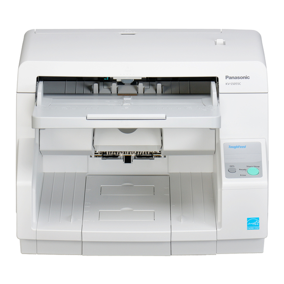
High Speed Color Scanner
KV-S5055C
Model No.
These instructions contain information on operating the scanner. Before reading these instructions, please read
the installation manual enclosed with this unit.
Please carefully read these instructions and the enclosed installation manual. Keep all documentation in a safe
place for future reference.
Advertisement
Table of Contents

Related Manuals for Panasonic KV-S5055C


Summary of Contents for Panasonic KV-S5055C
- Page 1 Operating Manual High Speed Color Scanner KV-S5055C Model No. These instructions contain information on operating the scanner. Before reading these instructions, please read the installation manual enclosed with this unit. Please carefully read these instructions and the enclosed installation manual. Keep all documentation in a safe...
-
Page 2: Feature Highlights
Introduction Introduction Thank you for purchasing a Panasonic High Speed Color Scanner. Feature Highlights Superior Paper Feeding • This scanner features an advanced paper-feeding mechanism that adjusts the pressure of the rollers and the amount of time that the rollers are applied to the document according to the condition of the document. -
Page 3: About The Documentation
(this manual) and maintenance of the unit. • You can view explanations about the settings for Panasonic Image Enhancement Technology (PIE) functions that are available on the ISIS driver screen and on the TWAIN driver screen by clicking the help button that appears on each of the software's operation screen. -
Page 4: System Requirements
Introduction International ENERGY STAR Program As an ENERGY STAR ® Partner, Panasonic has determined that this product meets the ENERGY STAR guidelines for energy efficiency. System Requirements PC/AT or compatible machine with a CD-ROM drive Computer ® ® Intel Core™ 2 Duo, 1.8 GHz or higher ®... - Page 5 Introduction Federal Communications Commission Requirements (For United States only) Note This equipment has been tested and found to comply with the limits for a Class A digital device, pursuant to Part 15 of the FCC Rules. These limits are designed to provide reasonable protection against harmful interference when the equipment is operated in a commercial environment.
-
Page 6: Table Of Contents
Table of Contents Table of Contents Before You Start ..................8 For Your Safety .........................8 Safety Information (For United Kingdom only) ............11 Precautions ........................12 Location of Controls ................14 Main Unit ..........................14 Control Panel and Status Indicators ................16 Operation ....................18 Turning on the Scanner Power ..................18 Preparing Documents .....................19 Acceptable Documents ....................19 Unacceptable Documents ....................21... - Page 7 Table of Contents Index......................89 Operating Manual...
-
Page 8: Before You Start
Before You Start Before You Start For Users For Your Safety To prevent severe injury and loss of life, read this WARNING section carefully before using the unit to ensure proper and safe operation of your unit. • This section explains the graphic symbols used in this manual. - Page 9 Before You Start Roller Cleaning Paper Do not attempt to repair the power cord or plug. If the power cord or plug is damaged Do not use the roller cleaning paper near or frayed, contact your dealer for a a heater or open flame. replacement.
- Page 10 Before You Start Make sure that the unit is installed in a well CAUTION ventilated room so as not to increase density of ozone in the air. Since ozone is heavier than air, it is recommended that air at floor level be Power ventilated.
-
Page 11: Safety Information (For United Kingdom Only)
A replacement fuse cover can be with the letter E or by the Earth symbol or coloured purchased from your local Panasonic Dealer. GREEN or GREEN-AND-YELLOW. The wire that is coloured BLUE must be connected to IF THE FITTED MOULDED PLUG IS UNSUITABLE... -
Page 12: Precautions
Do not move the unit immediately from a cold place refer to the Material Safety Data Sheet (MSDS). to a warm place. It may cause dew. Please ask your Panasonic sales company about obtaining the Material Safety Data Sheet. CD-ROM KEEP AWAY FROM FIRE. - Page 13 Before You Start Illegal Duplication Security Notice The management of documents and scanned data is It is unlawful to make duplication of certain the responsibility of the user. In particular, pay attention documents. to the following points. Duplicating certain documents may be illegal in •...
-
Page 14: Location Of Controls
Location of Controls Main Unit Front Document guides ADF door release Hopper extension tray Document guides selector Exit sub guide Exit tray Exit stopper Extension sub tray ADF door Manual feed selector Switches the scanning method between continuous scanning (Auto) and manual scanning (Manual). Hopper Control Panel For details, refer to "Control Panel and Status Indicators"... - Page 15 Location of Controls Rear Imprinter door You open this door when installing an imprinter unit (sold separately) or ink cartridge. For details on installing an imprinter, refer to "Installing the Imprinter Unit" (page 74). Fan exhaust vent AC inlet Power cord Plugs may vary in shape depending on country/area.
-
Page 16: Control Panel And Status Indicators
Location of Controls Control Panel and Status Indicators A Double Feed Skip key (DFS) If you press this key when a double feed occurs, the sheet that was detected as a double feed will be scanned, and scanning will continue. B Start/Stop key (Start/Stop) •... - Page 17 Location of Controls The status of the scanner is displayed by the ready indicator (C) and the error indicator (D), as shown in the table below: C Ready indicator D Error indicator Status (Green) (Red) Ready Blink (Slow) Caution Error Blink (Slow) Sleep Blink (Slow)
-
Page 18: Operation
Operation Turning on the Scanner Power Set the power switch (A) of the scanner to " " (ON). • The ready indicator (B) lights green. Operating Manual... -
Page 19: Preparing Documents
Operation Preparing Documents Acceptable Documents The acceptable documents for this scanner are as follows. Document size Paper thickness: 20 – 157 g/m² (5 – 42 lbs.) 48 - 297 mm • You can place up to 200 sheets of fresh, 75 g/m² (1.9 - 11.7 in.) (20 lbs.) paper on the hopper at one time. - Page 20 Operation For documents with mixed page sizes and thicknesses The ratio of page thickness between the thickest and thinnest Document thickness pages must be less than 1.5. The ratio of width and height between the largest page and smallest page must be less than 1.5. Document size Example: If the smallest page is A4 size, then the largest page can be up to A3 size, and if the smallest page is A6, then the largest...
-
Page 21: Unacceptable Documents
Operation Unacceptable Documents The following types of documents may not scan properly: • Torn or frayed documents • Curled, wrinkled or folded documents • Carbon paper • Thick or irregular documents such as envelopes, documents that are glued together, etc. •... -
Page 22: Scanning Documents
Operation Scanning Documents This scanner can scan documents whose pages are all the same size and documents whose pages are different sizes. Notice • Make sure to remove paper clips and staples from documents before scanning. Failing to do so can damage the unit, document, or both. -
Page 23: Scanning Documents With Pages Of The Same Size
Operation Scanning Documents with Pages of the Same Size Use the manual feed selector to select continuous scanning (Auto) or manual scanning (Manual). Continuous scanning (Auto) Manual scanning (Manual) Notice • When scanning a document manually (Manual), feed the document 1 page at a time. •... - Page 24 Operation Adjust the document guides (A) slightly larger than the actual size of the documents. Fan the documents. • Documents that have been stapled together or stacked together (as in a file folder) will need to be separated. Fan the stack of documents to separate all the edges. Hold both ends and bend the documents as shown in the illustration.
- Page 25 Operation Place the documents on the hopper (A) with the side to be scanned facing up. Then push the documents in the direction of the arrow until they stop. Notice • The height of the documents should not exceed the limit mark (B) on the document guide. This may cause a paper jam or skewing.
- Page 26 Operation Slide the document guides (A) to match the width of the document to be scanned. When scanning long sheets of paper Pull out the hopper extension tray (B) from the hopper. Operating Manual...
- Page 27 Operation Raise the exit stopper (A). When scanning long sheets of paper Adjust the exit stopper (B) and extension sub tray (C) to match the size of the document. Operating Manual...
- Page 28 Operation When scanning short sheets of paper When scanning documents like the one shown in the figure below, fully raise the exit stopper (D), and adjust the extension sub tray (E) to match the size of the document. Scanning direction Document Operating Manual...
- Page 29 Operation When scanning narrow documents (widths from 48 to 105 mm [1.89 to 4.13 in.]) Lower the exit sub guide (F). Notice • When you have finished using the exit sub guide, return it to its original position. Open your scanning application and scan the documents.
-
Page 30: Scanning Documents With Pages Of Different Sizes
Operation Scanning Documents with Pages of Different Sizes For conditions when scanning documents with mixed page sizes, see "For documents with mixed page sizes and thicknesses" (page 20). • When scanning different size documents, scanned sheets may need to be reordered for optimum performance. - Page 31 Operation Unlock the document guides. • Slide the document guides selector in the direction shown in the illustration until the (A) and (B) marks are aligned to unlock the document guides. Completely spread apart the document guides (A). Operating Manual...
- Page 32 Operation Fan the documents. • Documents that have been stapled together or stacked together (as in a file folder) will need to be separated. Fan the stack of documents to separate all the edges. Hold both ends and bend the documents as shown in the illustration. To flatten the documents, hold firmly and pull them apart as shown in the illustration.
- Page 33 Operation Place the documents on the hopper (A) with the scanning side facing up. • Align the document position so that the center of the smallest sheet will be fed to the center of the paper feed roller (B). If the document is not properly aligned, the pages will not be fed correctly. Notice •...
- Page 34 Operation When scanning long sheets of paper Pull out the hopper extension tray (D) from the hopper. Adjust the document guides (A) to the width of the document. Operating Manual...
- Page 35 Operation Remove the document and lock the document guides. • Slide the document guides selector in the direction shown in the illustration until the (A) and (B) marks are aligned to lock the document guides. Place the document on the hopper again and adjust the document guide according to the size of the document to be scanned.
- Page 36 Operation Raise the exit stopper (A). When scanning long sheets of paper Adjust the exit stopper (B) and extension sub tray (C) to match the largest document page. Operating Manual...
- Page 37 Operation When scanning short sheets of paper When scanning documents like the one shown in the figure below, fully raise the exit stopper (D), and adjust the extension sub tray (E) to match the size of the document. Scanning direction Document Open your scanning application and scan the documents.
-
Page 38: Adjusting The Left And Right Document Guides To Their Original Position
Operation Adjusting the left and right document guides to their original position Unlock the document guides. • Slide the document guides selector in the direction shown in the illustration until the (A) and (B) marks are aligned to unlock the document guides. Completely spread apart the document guides. - Page 39 Operation Lock the document guides. • Slide the document guides selector in the direction shown in the illustration until the (A) and (B) marks are aligned to lock the document guides. Operating Manual...
-
Page 40: Using Control Sheets
Operation Using Control Sheets By using control sheets, you can change the scanning conditions in the middle of scanning. Placing a control sheet in the middle of a document lets you change the scanning conditions for all pages scanned after the control sheet. -
Page 41: About Printing Control Sheets
Operation About Printing Control Sheets • Print the control sheet at the specified size; do not enlarge or reduce the size. • When printing the control sheet, make sure that the pattern is 25 mm (1 in.) from the top of the page and centered horizontally. -
Page 42: Printing Control Sheets
Operation Printing control sheets Note • In order to print control sheets, Adobe Reader must been installed on your computer. ® ® • Refer to the instruction manual for your printer for details about changing print settings. Insert the CD-ROM into the CD/DVD driver on your computer. •... -
Page 43: Changing The Scan Background Color
Operation Changing the Scan Background Color By switching the reference plates on the scanner, you can change the scanning background color between black and white. The default setting is black. Notice • Set the reference plate (F) and reference plate (B) to the same color. If the front and rear settings are different, then documents will not be scanned correctly. - Page 44 Operation Rotate the reference plate (F) (A) and the reference plate (B) (B). • With both hands, slowly rotate each plate in the direction indicated by the arrow. • Rotate each plate until the mark (C) on the outside of the reference plate and the mark (D) on the reference plate are aligned.
- Page 45 Operation Close the ADF door. • Push both sides of the ADF door down slowly until it clicks into place. Set the power switch of the scanner to " " (ON). Operating Manual...
-
Page 46: Care And Maintenance
Care and Maintenance Clearing Paper Jams Torn paper, thin paper or paper that is creased on the top edge may cause paper jams. If a paper jam occurs, remove the jammed sheet according to the following procedure. CAUTION • The scanning glass may be very hot after scanning a lot of documents. Remove the jammed sheet after the scanning glass's temperature has cooled. - Page 47 Care and Maintenance Remove the jammed sheet of paper. When a paper jam occurs inside the scanner: Remove the jammed sheet of paper from the inside of the ADF door. When a paper jam occurs at the exit slot: Pull the jammed paper from the exit slot (A) towards the front. Operating Manual...
- Page 48 Care and Maintenance Close the ADF door. • Push both sides of the ADF door down slowly until it clicks into place. Operating Manual...
-
Page 49: Cleaning The Scanner
Care and Maintenance Cleaning the Scanner Outside of the Scanner Notice • Do not use thinner, benzine, or cleaners containing abrasives or surfactants, for cleaning the outside of the scanner. • Clean the scanner at least once a month. Set the power switch (A) of the scanner to " "... - Page 50 Care and Maintenance Remove dirt and dust from the fan exhaust vent (A) with a brush. Operating Manual...
-
Page 51: Inside Of The Scanner
Only use the roller cleaning paper to clean the rollers and scanning glass. • For details about the roller cleaning paper, please refer to the Material Safety Data Sheet (MSDS). Please ask your Panasonic sales company about obtaining the Material Safety Data Sheet. Note •... - Page 52 Care and Maintenance How to use the blower Remove the brush tip from the blower (A), place it on the area that you want to clean (B), and then blow away any dirt, as shown in the following figure. • If dirt has accumulated, first remove the dirt with the brush tip of the blower, and then remove the brush tip and blow away the remaining dirt.
-
Page 53: Cleaning The Conveyor
Care and Maintenance Cleaning the Conveyor CAUTION • The scanning glass may be very hot after scanning a lot of documents. Clean the scanning glass after the temperature has cooled. Note • Clean the conveyor before cleaning the rollers. Set the power switch of the scanner to " "... - Page 54 Care and Maintenance With the included blower, blow away any dirt that has accumulated on the self-cleaning brushes (A). • Rotate the reference plates (B, C) in the direction indicated by the arrow so that you can see the brush. •...
- Page 55 Care and Maintenance With the included blower, blow away any dirt that has accumulated on the ion outlets (A). Notice • When cleaning the ion outlets, be sure to remove the brush tip from the blower. Using the blower with the brush tip still on might damage the ionizer. Close the ADF door.
-
Page 56: Cleaning The Rollers
Care and Maintenance Cleaning the Rollers CAUTION • The scanning glass may be very hot after scanning a lot of documents. Clean the scanning glass after the temperature has cooled. Set the power switch of the scanner to " " (OFF). Pull the ADF door release (A) towards you, and open the ADF door (B). - Page 57 Care and Maintenance Use the roller cleaning paper (page 51) to remove the dirt from the surfaces of all rollers. Direction to wipe rollers Double feed prevention roller, Separation roller Other rollers Notice • After removing the double feed prevention roller, gently wipe dirt from the surface of the roller in the direction indicated by the arrows in the illustration.
- Page 58 Care and Maintenance Location of Rollers Paper feed roller Separation roller Free rollers Double feed prevention roller Drive rollers Operating Manual...
- Page 59 Care and Maintenance Close the ADF door. • Push both sides of the ADF door down slowly until it clicks into place. Set the power switch of the scanner to " " (ON). Reset the roller cleaning counter in User Utility to 0. •...
-
Page 60: Cleaning The Sensors And Scanning Glass
Care and Maintenance Cleaning the Sensors and Scanning Glass CAUTION • The scanning glass may be very hot after scanning a lot of documents. Clean the scanning glass after the temperature has cooled. Set the power switch of the scanner to " "... - Page 61 Care and Maintenance Remove dirt on the sensors (A, B, C, D, G) and reflectors (J) with the included blower, then wipe the scanning glass (E, I) and reference plates (F, H) with the roller cleaning paper (page 51). Location of Sensors Waiting sensor Double feed detector Slip detect sensor...
- Page 62 Care and Maintenance Location of Reflectors Reflectors Operating Manual...
- Page 63 Care and Maintenance Close the ADF door. • Push both sides of the ADF door down slowly until it clicks into place. Set the power switch of the scanner to " " (ON). Operating Manual...
-
Page 64: Replacement Parts And Optional Units
Replacement Parts and Optional Units Replacement Parts and Optional Units Part Name Part Number Notes Roller exchange kit • Paper feed roller module KV-SS039 – • Double feed prevention roller Replacement See "About the roller cleaning Parts Roller cleaning paper KV-SS03 paper"... -
Page 65: Replacing Parts
Replacement Parts and Optional Units Replacing Parts If double feeding or paper jam occurs frequently even after cleaning the roller (page 56), please call your dealer to order a "Roller exchange kit (KV-SS039)", and replace the paper feed roller module and double feed prevention roller. - Page 66 Replacement Parts and Optional Units Move the lever (A) of the paper feed roller module in the order indicated by the arrow (A, B), and then pull out the module towards you. Take out the new paper feed roller module in the optional "Roller exchange kit (KV-SS039)". Operating Manual...
- Page 67 Replacement Parts and Optional Units Install the new paper feed roller module. • With the lever (A) of the paper feed roller module lowered, insert both protrusions (B) into the grooves (C), and then slowly raise the lever in the direction indicated by the arrow until it clicks into place. Notice •...
- Page 68 Replacement Parts and Optional Units Close the ADF door. • Push both sides of the ADF door down slowly until it clicks into place. Plug in the power cord, and set the power switch of the scanner to " " (ON). Operating Manual...
-
Page 69: Replacing The Double Feed Prevention Roller
Replacement Parts and Optional Units Replacing the Double Feed Prevention Roller Set the power switch (A) of the scanner to " " (OFF), and unplug the power cord. Pull the ADF door release (A) towards you, and open the ADF door (B). Operating Manual... - Page 70 Replacement Parts and Optional Units Pull towards you and remove the double feed prevention roller cover by using the indent (A). While pulling the tab (A) in the direction indicated by the arrow, lift the double feed prevention roller (B) in the direction of the arrow.
- Page 71 Replacement Parts and Optional Units Install the new double feed prevention roller. • Align the shaft that is shaped as indicated by A with the notch in the roller mount (B), and then insert the shaft in the notch. Push the shaft on the opposite side (C) until it clicks into place. Notice •...
- Page 72 Replacement Parts and Optional Units Insert the protrusion (A) of the double feed prevention roller cover into the hole on the main unit, and then push in the part of the roller cover indicated by B in the direction indicated by the arrow until it clicks into place.
- Page 73 Replacement Parts and Optional Units Plug in the power cord, and set the power switch of the scanner to " " (ON). Reset the roller replacing counter in User Utility to 0. • Start User Utility, and in the window, click the [Clear Counter] button for "After Replace Roller" to reset the counter to 0.
-
Page 74: Installing Optional Units
Replacement Parts and Optional Units Installing Optional Units Installing the Imprinter Unit The imprinter prints on the face of the document before scanning. The printed material will also be scanned. Set the power switch (A) of the scanner to " "... - Page 75 Replacement Parts and Optional Units Connect the cable. Notice • Be sure to correctly match the rib with the slot prior to inserting the connector. While keeping the direction of the imprinter as shown in the diagram below, insert the pins (A) on both sides into the guides, and insert the pins (B) on both sides into the guides until they are locked by the springs (C).
- Page 76 Replacement Parts and Optional Units Close the imprinter door. Set the power switch of the scanner to " " (ON). Note • For details on installing an ink cartridge, refer to "Installing the Ink Cartridge" (page 77). Operating Manual...
-
Page 77: Installing The Ink Cartridge
Replacement Parts and Optional Units Installing the Ink Cartridge Install the ink cartridge in the imprinter. Set the power switch (A) of the scanner to " " (OFF). Remove the protective tape. Operating Manual... - Page 78 Replacement Parts and Optional Units Move the carriage to the ink cartridge exchange position. Notice • Adjust the position following the label on the imprinter. Insert the ink cartridge into the carriage. Lock the ink cartridge adjustment lever (A). Operating Manual...
-
Page 79: Removing The Ink Cartridge
Replacement Parts and Optional Units Removing the ink cartridge Set the power switch of the scanner to " " (OFF). Move the carriage to the ink cartridge exchange position. Notice • Adjust the position following the label on the imprinter. Pinch the ink cartridge adjustment lever (A) and lift it. -
Page 80: Printing
Replacement Parts and Optional Units Printing Adjusting the imprinter printing position Move the carriage to the desired printing position, and align the indicator (A) with the " " mark (B) . • The " " mark indicates the printing position. Printing is not available in any other position. Printing Position 141 mm (5.6 in.) 121 mm (4.8 in.) -
Page 81: Appendix
Appendix Troubleshooting If a problem occurs while the scanner is being used, check the following items and check the scanner status with the User Utility. If the unit still malfunctions, turn it OFF, unplug the power cord and call for service. Symptom Possible Cause Remedy... - Page 82 Appendix Symptom Possible Cause Remedy Clean the paper feed roller, The paper feed roller, separation separation roller, double feed roller, double feed prevention roller, prevention roller, drive rollers, or free drive rollers, or free rollers are dirty. rollers. (page 56) The sensors and/or reflector plate are Clean all of the sensors and the dirty.
- Page 83 Appendix Symptom Possible Cause Remedy The document guides are not Adjust the document guides properly adjusted to the size of the document to the size of the document to be to be scanned, or the document to be scanned (page 22). scanned is set slanted on the hopper.
-
Page 84: Shading Adjustment
Appendix Shading Adjustment About shading adjustment The shading adjustment function corrects variations in the lamp intensity and pixel sensor sensitivity, and reduces unevenness in density in scanned images. It can be carried out by means of the User Utility using the special shading paper, which is provided with this scanner. -
Page 85: Repacking Instructions
Appendix Repacking Instructions It is highly recommended that you keep the original carton and ALL packing materials. If you need to transport or ship the scanner, please follow these instructions. Note • Improper repacking of the scanner may result in a service charge to repair the scanner. •... - Page 86 Appendix Pack the scanner. A Joint B USB cable C Power cord D Double feed prevention roller E Blower • Drivers & Utilities / Manuals CD-ROM • Installation Manual • Shading paper • Roller cleaning paper Operating Manual...
-
Page 87: Specifications
The scanning speed differs depending on the host computer, the operating system, the application, the measuring method, the quantity of data in the image, and the paper type. The scanning speed depends on a measuring method of Panasonic. Scan quality cannot be guaranteed for documents with a non-standard size. - Page 88 Appendix Item KV-S5055C External dimensions 468 ´ 444 ´ 339 mm (18.5 ´ 17.5 ´ 13.4 in.) (Width ´ Depth ´ Height) Weight 18 kg (40 lbs.) AC100 – 120 V, 50/60 Hz, 1.0 A Power requirement AC100 – 240 V, 50/60 Hz, 1.0 – 0.5 A...
- Page 89 Index Index Hopper extension tray Image control Imprinter door AC inlet Imprinter unit 64, 74 ADF door Ink cartridge 64, 77 ADF door release Interface Background color Joint Blower 52, 86 Limit mark 25, 33 Cleaning the conveyor Cleaning the rollers Cleaning the scanner Cleaning the sensors Manual feed selector...
- Page 90 Index Safety information Scanning face Scanning glass Scanning method Scanning speed Sensors Double feed detector Paper sensor Slip detect sensor Starting sensor Waiting sensor Shading adjustment Shading paper Specifications Start/Stop key Status indicators Storage Environment System Requirements Tonal gradation Troubleshooting USB cable USB connector User Utility...
- Page 91 One Panasonic Way, Secaucus, New Jersey 07094 5770 Ambler Drive, Mississauga, Ontario, L4W 2T3 Willoughby Road, Bracknell, Berkshire, RG12 8FP Hagenauer Strasse 43, 65203 Wiesbaden, Germany For information of Compliance with EU relevant Regulatory Directives, Contact to Authorised Representative: Panasonic Testing Centre...