Table of Contents
Advertisement
Advertisement
Table of Contents

Related Manuals for Asus F2A85-V PRO


Summary of Contents for Asus F2A85-V PRO
- Page 1 F2A85-V PRO...
- Page 2 Product warranty or service will not be extended if: (1) the product is repaired, modified or altered, unless such repair, modification of alteration is authorized in writing by ASUS; or (2) the serial number of the product is defaced or missing.
-
Page 3: Table Of Contents
1.3.2 Dual Intelligent Processors 3 with New DIGI+ Power Control ................1-2 1.3.3 ASUS Exclusive Features ..........1-4 1.3.4 ASUS Quiet Thermal Solutions ........1-5 1.3.5 ASUS EZ DIY ..............1-6 Chapter 2: Hardware information Before you proceed ..............2-1 Motherboard overview .............. - Page 4 Exit menu ..................3-32 3.10 Updating BIOS ................3-33 3.10.1 ASUS Update utility ............3-33 3.10.2 ASUS EZ Flash 2 utility ..........3-36 3.10.3 ASUS CrashFree BIOS 3 utility ........3-37 3.10.4 ASUS BIOS Updater ............. 3-38 Chapter 4: Software support Installing an operating system ...........
- Page 5 Contents 4.3.7 Probe II ................. 4-28 4.3.8 Sensor Recorder ............4-29 4.3.9 USB Charger+ ............... 4-30 4.3.10 USB 3.0 Boost .............. 4-32 4.3.11 Network iControl ............4-33 4.3.12 USB BIOS Flashback Wizard ........4-37 4.3.13 MyLogo2 ............... 4-39 4.3.14 Audio configurations ............. 4-41 RAID configurations ..............
-
Page 6: Safety Information
Safety information Electrical safety • To prevent electrical shock hazard, disconnect the power cable from the electrical outlet before relocating the system. • When adding or removing devices to or from the system, ensure that the power cables for the devices are unplugged before the signal cables are connected. If possible, disconnect all power cables from the existing system before you add a device. -
Page 7: About This Guide
Refer to the following sources for additional information and for product and software updates. ASUS websites The ASUS website provides updated information on ASUS hardware and software products. Refer to the ASUS contact information. Optional documentation Your product package may include optional documentation, such as warranty flyers, that may have been added by your dealer. -
Page 8: Conventions Used In This Guide
Conventions used in this guide To ensure that you perform certain tasks properly, take note of the following symbols used throughout this manual. DANGER/WARNING: Information to prevent injury to yourself when trying to complete a task. CAUTION: Information to prevent damage to the components when trying to complete a task. -
Page 9: F2A85-V Pro Specifications Summary
32-bit operating system. ® ** The 64GB maximum memory capacity can be supported with 16GB DIMMs or above. ASUS will update the Memory QVL (Qualified Vendors List) once the DIMMs are available on the market. *** Refer to www.asus.com for the latest Memory QVL (Qualified Vendors List). - Page 10 - 10 x USB 2.0/1.1 ports (2 ports at the back panel, 8 ports at the mid-board) ASUS unique ASUS Dual Intelligent Processors 3 with New DIGI+ Power features Control: - Industry leading digital 6+2 phase power design...
- Page 11 F2A85-V PRO specifications summary ASUS unique ASUS EZ DIY features - ASUS UEFI BIOS EZ Mode featuring friendly graphics user interface - ASUS USB BIOS Flashback with USB BIOS Flashback Wizard for EZ BIOS download scheduling - DirectKey - ASUS CrashFree BIOS 3...
- Page 12 64Mb Flash ROM, UEFI BIOS, PnP, DMI v2.0, WfM 2.0, ACPI v3.0, SM BIOS 2.7, Multi-language BIOS, ASUS EZ Flash 2, ASUS CrashFree BIOS 3, F12 PrintScreen Function, F3 Shortcut Function and ASUS DRAM SPD (Serial Presence Detect) Memory information...
-
Page 13: Chapter 1: Product Introduction
® The motherboard delivers a host of new features and latest technologies, making it another standout in the long line of ASUS quality motherboards! Before you start installing the motherboard, and hardware devices on it, check the items in your package with the list below. -
Page 14: Special Features
DRAM tuning in addition to ultra-precise APU voltage control. It’s upgraded with one-click extreme performance optimization with the user-friendly AI Suite II utility. This evolution of innovative and industry-leading ASUS technology provides super-accurate voltage tuning for better efficiency, stability and performance. -
Page 15: Asus Turbov
ASUS TurboV Easy, Real-Time O.C. Tunings Feel the adrenaline rush of real-time OC-now a reality with the ASUS TurboV. This easy OC tool allows you to overclock without exiting or rebooting the OS; and its user-friendly interface makes overclock with just a few clicks away. Moreover, the ASUS OC profiles in TurboV provides the best O.C. -
Page 16: Asus Exclusive Features
USB 3.0 Boost Faster USB 3.0 Transmission with UASP New ASUS USB 3.0 Boost technology supports UASP (USB Attached SCSI Protocol), the latest USB 3.0 standard. With USB 3.0 Boost technology, a USB device’s transmission speed is significantly increased up to 170%, adding to an already impressive fast USB 3.0 transfer speed. -
Page 17: Asus Quiet Thermal Solutions
Protect your computer with ESD Guards. Electrostatic discharge (ESD) conditions can happen while plugging or unplugging any USB peripherals-causing damage to the computer. ASUS ESD Guards clamp the ESD voltage and shunt the majority of the ESD current away for a more reliable computing environment. -
Page 18: Asus Ez Diy
POST. It also allows you to turn on and turn off your system and conveniently enter the BIOS during bootup. ASUS EZ-Flash 2 ASUS EZ Flash 2 is a user-friendly utility that allows you to update the BIOS without using a bootable floppy disk or an OS-based utility. ASUS MyLogo2™... - Page 19 Simply restore corrupted BIOS data from USB flash disk The ASUS CrashFree BIOS 3 allows users to restore corrupted BIOS data from a USB flash disk containing the BIOS file. This utility saves users the cost and hassle of buying a replacement BIOS chip.
- Page 20 Chapter 1: Product Introduction...
-
Page 21: Chapter 2: Hardware Information
• Before you install or remove any component, ensure that the ATX power supply is switched off or the power cord is detached from the power supply. Failure to do so may cause severe damage to the motherboard, peripherals, or components. ASUS F2A85-V PRO... -
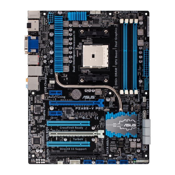
Page 22: Motherboard Overview
Motherboard overview 2.2.1 Motherboard layout 24.4cm(9.6in) CPU_FAN CHA_FAN3 KBMS_USB12 EPU_LED DIGI+ DIGI+ SPDIFO EATX12V _HDMI 1445 MemOK! DRAM_LED ESATA6G_ USB3_12 LAN_USB3_E12 AUDIO CHA_FAN1 PCIEX1_1 Lithium Cell CMOS Power 8111F PCIEX16_1 CHA_FAN4 F2A85-V PRO 1042 PCIEX1_2 477D ® PCI1 A85X PCIEX16_2 Super PCI2 64Mb... -
Page 23: Layout Contents
19. USB 2.0 connectors (10-1 pin USB34, USB56, USB78, USB910) 2-23 20. Direct connector (2-pin DRCT) 2-26 21. Serial port connector (10-1 pin COM1) 2-25 22. Front panel audio connector (10-1 pin AAFP) 2-23 23. Digital audio connector (4-1 pin SPDIF_OUT) 2-24 ASUS F2A85-V PRO... -
Page 24: Accelerated Processing Unit (Apu)
2.2.2 Accelerated Processing Unit (APU) This motherboard comes with an FM2 socket designed for AMD™ A-Series Accelerated processors. Ensure that you use a APU designed for the FM2 socket. The APU fits in only one correct orientation. DO NOT force the APU into the socket to prevent bending the pins and damaging the APU! F2A85-V PRO F2A85-V PRO CPU socket FM2... -
Page 25: System Memory
A DDR3 module is notched differently from a DDR or DDR2 module. DO NOT install a DDR or DDR2 memory module to the DDR3 slot. F2A85-V PRO F2A85-V PRO 240-pin DDR3 DIMM sockets Recommended memory configurations We recommend that you install the memory modules from the blue slots for better overclocking capability. ASUS F2A85-V PRO... -
Page 26: Memory Configurations
Memory configurations You may install 1GB, 2GB, 4GB and 8GB unbuffered non-ECC DDR3 DIMMs into the DIMM sockets. • You may install varying memory sizes in Channel A and Channel B. The system maps the total size of the lower-sized channel for the dual-channel configuration. Any excess memory from the higher-sized channel is then mapped for single-channel operation. - Page 27 8GB(2 x 4GB) 9-10-9-28 1.5V G.SKILL F3-14900CL9Q-8GBXL(XMP) 8GB(2GBx4) 9-9-9-24 1.6V Kingston KHX1866C9D3K4/16GX(XMP) 16GB ( 4GB x4 ) DS 1.65V Kingston KHX1866C9D3T1K3/6GX(XMP) 6GB(3 x 2GB) 1.65V Kingston KHX1866C11D3P1K2/8G 8GB ( 4GB x 2) 1.5V Kingston KHX1866C9D3K2/8GX(XMP) 8GB(4GBX2) 1.65V ASUS F2A85-V PRO...
- Page 28 DDR3 1600 MHz capability DIMM socket support Chip (Optional) Vendors Part No. Size Chip NO. Timing Voltage Brand 1 DIMM 2 DIMMs 4 DIMMs 3CCD-1509A A-DATA AM2U16BC2P1 DATA EL1126T 1.55V- A-DATA AX3U1600XB2G79-2X(XMP) 4GB(2 x 2GB) 7-9-7-21 1.75V 3CCD-1509A A-DATA AM2U16BC4P2 DATA EL1126T 1.55V-...
- Page 29 4GB(2 x 2GB) DS - 9-9-9-24 1.50V Corsair CM3X4GA1333C9N2 DS Corsair 256MBDCJGELC04 9-9-9-24 - 01136 Corsair CMX4GX3M1A1333C9 DS - 9-9-9-24 1.50V Corsair CMD8GX3M4A1333C7 8GB(4 x 2GB) DS - 7-7-7-20 1.60V Crucial CT12864BA1339.8FF SS Micron 9FF22D9KPT (continued on the next page) ASUS F2A85-V PRO...
- Page 30 DDR3 1333 MHz capability DIMM socket support Chip (Optional) Vendors Part No. Size Chip NO. Timing Voltage Brand 1 DIMM 2 DIMMs 4 DIMMs Crucial CT25664BA1339.16FF DS Micron 9KF27D9KPT Crucial BL25664BN1337.16FF 6GB(3 x 2GB) DS - 7-7-7-24 1.65V (XMP) ELPIDA EBJ10UE8EDF0-DJ-F SS ELPIDA J1108EDSE-DJ-F...
- Page 31 C304627CB1AG22Fe RiDATA RiDATA E304459CB1AG32Cf RiDATA Silicon SP002GBLTU133V02 S-POWER 20YT3NG-1202 Power SILICON SP002GBLTU133S02 Elixir N2CB1680AN-C6 POWER Silicon SP004GBLTU133V02 S-POWER 20YT3NG-1201 Power TAKEMS TMS2GB364D081-107EY 7-7-7-20 1.5V TAKEMS TMS2GB364D082-138EW 8-8-8-24 1.5V UMAX E41302GP0-73BDB UMAX U2S24D30TP-13 WINTEC 3WVS31333-2G-CNR AMPO AM3420803-13H ASUS F2A85-V PRO 2-11...
- Page 32 A2 and B2 for better compatibility. • 4 DIMMs: Supports four (4) modules inserted into both the blue and black slots as two pairs of Dual-channel memory configuration. Visit the ASUS website for the latest QVL. 2-12 Chapter 2: Hardware information...
-
Page 33: Expansion Slots
PCIe 2.0 x16_3 slot [black] (at x4 mode, compatible with PCIe x1 and x4 devices) PCI Express operating mode VGA configuration PCIe 2.0 x16_1 PCIe 2.0 x16_2 Single VGA/PCIe card (Recommend for single VGA) Dual VGA/PCIe card ASUS F2A85-V PRO 2-13... -
Page 34: Irq Assignments For This Motherboard
• In single VGA card mode, use the PCIe 2.0 x16_1 slot (navy blue) for a PCI Express x16 graphics card to get better performance. • In CrossFireX™ mode, use the PCIe 2.0 x16_1 and PCIe 2.0 x16_2 slots for PCI Express x16 graphics cards to get better performance. -
Page 35: Jumper
• You do not need to clear the RTC when the system hangs due to overclocking. For system failure due to overclocking, use the C.P.R. (CPU Parameter Recall) feature. Shut down and reboot the system so the BIOS can automatically reset parameter settings to default values. ASUS F2A85-V PRO 2-15... -
Page 36: Onboard Switches
BIOS default settings. A message will appear during POST reminding you that the BIOS has been restored to its default settings. • We recommend that you download and update to the latest BIOS version from the ASUS website at www.asus.com after using the MemOK! function. - Page 37 EPU switch This switch allows you to enable or disable the EPU function. F2A85-V PRO F2A85-V PRO EPU switch To ensure system performance, turn the switch setting to Enable when the system is powered off. ASUS F2A85-V PRO 2-17...
- Page 38 • The EPU LED near the TPU switch lights when the switch setting is turned to Enable. • If you change the switch setting to Enable under the OS environment, the EPU function will be activated after the next system bootup. •...
- Page 39 BIOS_FLBK F2A85-V PRO BIOS Flashback switch Download the USB BIOS Flashback wizard from the ASUS service website (www.asus. com). Save it to a USB portable disk, and place it in the root directory. Plug the USB flash drive into the bottom port of ESATA6G_USB3_12 connector in back I/O.
-
Page 40: Onboard Leds
2.2.7 Onboard LEDs Standby Power LED The motherboard comes with a standby power LED. The green LED lights up to indicate that the system is ON, in sleep mode, or in soft-off mode. This is a reminder that you should shut down the system and unplug the power cable before removing or plugging in any motherboard component. - Page 41 The EPU LED lights when the EPU switch is turned to Enable. EPU_LED F2A85-V PRO F2A85-V PRO EPU LED TPU LED The TPU LED lights when the TPU switch is turned to Enable. F2A85-V PRO TPU_LED F2A85-V PRO TPU LED ASUS F2A85-V PRO 2-21...
-
Page 42: Internal Connectors
2.2.8 Internal connectors Serial ATA 6.0 Gb/s connectors (7-pin SATA6G_1~7) These connectors connect to Serial ATA 6.0 Gb/s hard disk drives via Serial ATA 6.0 Gb/s signal cables. If you installed Serial ATA hard disk drives, you can create a RAID 0, 1, 5, and 10 configuration through the onboard AMD A85X chipset. -
Page 43: Front Panel Audio Connector
Front Panel Type item in the BIOS setup to [HD]; if you want to connect an AC'97 front panel audio module to this connector, set the item to [AC 97]. By default, this connector is set to [HD]. Refer to 3.5.5 Onboard Devices Configuration for details. ASUS F2A85-V PRO 2-23... - Page 44 Digital audio connector (4-1 pin SPDIF_OUT) This connector is for an additional Sony/Philips Digital Interface (S/PDIF) port. Connect the S/PDIF Out module cable to this connector, then install the module to a slot opening at the back of the system chassis. F2A85-V PRO SPDIF_OUT F2A85-V PRO Digital audio connector...
- Page 45 USB3_34 F2A85-V PRO F2A85-V PRO USB3.0 Front panel connector You can connect the ASUS front panel USB 3.0 bracket to this connector to obtain the front panel USB 3.0 solution. Serial port connector (10-1 pin COM1) This connector is for a serial (COM) port. Connect the serial port module cable to this connector, then install the module to a slot opening at the back of the system chassis.
- Page 46 The system may become unstable or may not boot up if the power is inadequate. • If you are uncertain about the minimum power supply requirement for your system, refer to the Recommended Power Supply Wattage Calculator at http://support.asus.com/ PowerSupplyCalculator/PSCalculator.aspx?SLanguage=en-us for details. Direct connector (2-pin DRCT) This connector is for the chassis-mounted button that supports the DirectKey function.
-
Page 47: System Panel Connector
Pressing the power switch for more than four seconds while the system is ON turns the system OFF. • Reset button (2-pin RESET) This 2-pin connector is for the chassis-mounted reset button for system reboot without turning off the system power. ASUS F2A85-V PRO 2-27... -
Page 48: Building Your Computer System
Building your computer system 2.3.1 Additional tools and components to build a PC system 1 bag of screws Philips (cross) screwdriver PC chassis Power supply unit AMD FM2 APU AMD FM2 compatible CPU Fan DIMM SATA hard disk drive SATA optical disc drive (optional) Graphics card (optional) The tools and components in the table above are not included in the motherboard package. -
Page 49: Apu Installation
Ensure that you use a APU designed for the FM2 socket. The APU fits in only one correct orientation. DO NOT force the APU into the socket to prevent bending the pins and damaging the APU! ASUS F2A85-V PRO 2-29... -
Page 50: Apu Heatsink And Fan Assembly Installation
2.3.3 APU heatsink and fan assembly installation Apply the Thermal Interface Material to the APU heatsink and APU before you install the heatsink and fan if necessary. To install the APU heatsink and fan assembly 2-30 Chapter 2: Hardware information... - Page 51 To uninstall the APU heatsink and fan assembly ASUS F2A85-V PRO 2-31...
-
Page 52: Dimm Installation
2.3.4 DIMM installation To remove a DIMM 2-32 Chapter 2: Hardware information... -
Page 53: Motherboard Installation
2.3.5 Motherboard installation The diagrams in this section are for reference only. The motherboard layout may vary with models, but the installation steps remain the same. ASUS F2A85-V PRO 2-33... - Page 54 F2A85-V PRO DO NOT overtighten the screws! Doing so can damage the motherboard. 2-34 Chapter 2: Hardware information...
-
Page 55: Atx Power Connection
2.3.6 ATX Power connection ASUS F2A85-V PRO 2-35... -
Page 56: Sata Device Connection
2.3.7 SATA device connection 2-36 Chapter 2: Hardware information... -
Page 57: Front I/O Connector
2.3.8 Front I/O Connector To install ASUS Q-Connector To install USB 2.0 Connector To install front panel audio connector AAFP USB 2.0 To install USB 3.0 Connector USB 3.0 ASUS F2A85-V PRO 2-37... -
Page 58: Expansion Card Installation
2.3.9 Expansion Card installation To install PCIe x16 cards To install PCIe x1 cards To install PCI cards 2-38 Chapter 2: Hardware information... -
Page 59: Rear Panel Connection
ASMedia USB 3.0 ports 1 and 2, PS/2 keyboard/mouse combo port support ASUS USB 3.0 Boost UASP Mode AMD USB 3.0 ports 1 and 2, support ASUS USB Optical S/PDIF Out port 3.0 Boost UASP Mode. Bottom port supports USB... -
Page 60: Lan Port Led Indications
* LAN port LED indications ACT/LINK SPEED Activity Link LED Speed LED Status Description Status Description No link 10 Mbps connection ORANGE Linked ORANGE 100 Mbps connection LAN port BLINKING Data activity GREEN 1 Gbps connection ** Audio 2, 4, 6, or 8-channel configuration Headset Port 4-channel... -
Page 61: Audio I/O Connections
2.3.11 Audio I/O connections Audio I/O ports Connect to Headphone and Mic Connect to Stereo Speakers Connect to 2.1 channel Speakers ASUS F2A85-V PRO 2-41... - Page 62 Connect to 4.1 channel Speakers Connect to 5.1 channel Speakers Connect to 7.1 channel Speakers 2-42 Chapter 2: Hardware information...
-
Page 63: Starting Up For The First Time
While the system is ON, pressing the power switch for less than four seconds puts the system on sleep mode or soft-off mode, depending on the BIOS setting. Pressing the power switch for more than four seconds lets the system enter the soft-off mode regardless of the BIOS setting. ASUS F2A85-V PRO 2-43... - Page 64 2-44 Chapter 2: Hardware information...
-
Page 65: Chapter 3: Bios Setup
BIOS setup Knowing BIOS The ASUS UEFI BIOS offers a user-friendly interface that goes beyond traditional keyboard-only BIOS controls to enable more flexible and convenient mouse input. Users can easily navigate the UEFI BIOS with the same smoothness as their operating system. -
Page 66: Ez Mode
Loads optimized default Power Saving mode Selects the boot device priority Normal mode ASUS Optimal mode Selects the Advanced Selects the boot device priority mode functions Displays the system properties of the selected mode on the right hand side •... -
Page 67: Advanced Mode
For displaying the system temperature, power status, and changing the Monitor fan settings. Boot For changing the system boot configuration Tool For configuring options for special functions Exit For selecting the exit options and loading default settings ASUS F2A85-V PRO... -
Page 68: Menu Items
Menu items The highlighted item on the menu bar displays the specific items for that menu. For example, selecting Main shows the Main menu items. The other items (Ai Tweaker, Advanced, Monitor, Boot, Tool, and Exit) on the menu bar have their respective menu items. -
Page 69: Main Menu
RAM to clear the BIOS password. See section 2.2.5 Jumper for information on how to erase the RTC RAM. • The Administrator or User Password items on top of the screen show the default Not Installed. After you set a password, these items show Installed. ASUS F2A85-V PRO... -
Page 70: Administrator Password
Administrator Password If you have set an administrator password, we recommend that you enter the administrator password for accessing the system. Otherwise, you might be able to see or change only selected fields in the BIOS setup program. To set an administrator password: Select the Administrator Password item and press <Enter>. -
Page 71: Ai Tweaker Menu
NB VREF Voltage 0.750V Auto F2: Previous Values F3: Shortcut DRAM VREFCA Voltage 0.750V Auto F5: Optimized Defaults F10: Save ESC: Exit DRAM VREFDQ Voltage 0.750V Auto F12: Print Screen Version 2.10.1208. Copyright (C) 2011 American Megatrends, Inc. ASUS F2A85-V PRO... - Page 72 Ai Overclock Tuner [Auto] Allows you to select the CPU overclocking options to achieve the desired CPU internal frequency. Select any of these preset overclocking configuration options: [Auto] Loads the optimal settings for the system. [Manual] Allows you to individually set overclocking parameters. The following item appears only when you set the Ai Overclocking Tuner item to [Manual].
-
Page 73: Dram Timing Control
Configuration options: �100%�� �110%�� �120%�� �130%�� �140%�� CPU/NB Current Capability [100%] This item provides wider total power range for overclocking. A higher value brings a wider total power range and extends the overclocking frequency range simultaneously. Configuration options: �100%�� �110%�� �120%�� �130%�� ASUS F2A85-V PRO... - Page 74 VRM efficiency. [Standard] Proceeds to phase control depending on the CPU loading. �Optimized�� Loads the ASUS optimized phase tuning profile. [Extreme] Proceeds to the full phase mode. [Manual Adjustment] Allows manual adjustment.
-
Page 75: Cpu Offset Mode Sign
[Auto] Allows you to set the Auto mode. �Optimized�� Allows you to set the ASUS optimized phase tuning profile. [Extreme] Allows you to set the full phase mode. Do not remove the thermal module while changing the DIGI+ Power Control related parrameters . - Page 76 VDDNB Manual Voltage [Auto] This item appears only when you set the CPU Voltage item to [Manual Mode] and allows you to set a fixed VDDNB voltage. The values range from 0.800V to 1.750V with a 0.00625V interval. DRAM Voltage [Auto] Allows you to set the DRAM voltage.
-
Page 77: Advanced Menu
→←: Select Screen ↑↓: Select Item Enter: Select +/-: Change Opt. F1: General Help F2: Previous Values F3: Shortcut F5: Optimized Defaults F10: Save ESC: Exit F12: Print Screen Version 2.10.1208. Copyright (C) 2012 American Megatrends, Inc. ASUS F2A85-V PRO 3-13... -
Page 78: Cpu Configuration
3.5.1 CPU Configuration The items in this menu show the CPU-related information that the BIOS automatically detects. The items shown in this screen may be different due to the CPU you installed. UEFI BIOS Utility - Advanced Mode Exit Ai Tweaker Main Advanced Monitor... -
Page 79: Sata Configuration
7, and the eSATA port are configured as �AHCI��, the ports can only be used under OS with driver installed. Set to [IDE] instead of [AHCI] to access devices on SATA ports 5, 6, 7, and the eSATA port before entering OS. Configuration options: �AHCI�� �IDE�� ASUS F2A85-V PRO 3-15... -
Page 80: Usb Configuration
SATA Port 5, 6, 7, ESATA [RAID] This item only appears when OnChip SATA Type is set to [RAID]. If SATA ports 5, 6, 7, and the eSATA port are configured as �RAID��, the ports can only be used under OS with driver installed. -
Page 81: Nb Configuration
Enables the integrated graphics controller. Configuration options: �Auto�� �Force�� UMA Frame Buffer Size [Auto] Configuration options: �Auto�� �32M�� �64M�� �128M�� �256M�� �512M�� �1G�� �2G�� HDMI/DVI Port Output [Auto] Sets the HDMI/DVI port output type. Configuration options: �Auto�� �HDMI�� �DVI�� ASUS F2A85-V PRO 3-17... -
Page 82: Onboard Devices Configuration
PCIex16_1 [Auto] Sets the speed mode for the PCIex16_1 slot. When [Force X16] is selected, the PCIex16_1 slot will be disabled. Configuration options: �Auto�� �Force X16�� �Force X8�� 3.5.5 Onboard Devices Configuration UEFI BIOS Utility - Advanced Mode Exit Ai Tweaker Main Advanced Monitor... -
Page 83: Apm
Specify what state to go to when power is re-applied after a power failure (G3 state). Power On By PS/2 Keyboard Disabled Power On By PME Disabled Power On By Ring Disabled Power On By RTC Disabled ASUS F2A85-V PRO 3-19... - Page 84 Restore AC Power Loss [Power Off] [Power On] The system goes into on state after an AC power loss. [Power Off] The system goes into off state after an AC power loss. [Last State] The system goes into either off or on state, whatever the system state was before the AC power loss.
-
Page 85: Network Stack
Ipv6 Delay Time [0] This item appears only when you set the Network Stack item to [Enabled] and allows you to set the time delay before IPV6 PXE boot. Use the <+> and <-> keys to adjust the value. ASUS F2A85-V PRO 3-21... -
Page 86: Monitor Menu
Monitor menu The Monitor menu displays the system temperature/power status, and allows you to change the fan settings. UEFI BIOS Utility - Advanced Mode Exit Main Ai Tweaker Advanced Monitor Boot Tool CPU Temperature +73ºC / +163ºF +73ºC / +163ºF MB Temperature +31ºC / +87ºF CPU_FAN Speed... - Page 87 20% to 100%. When the CPU temperature reaches the upper limit, the CPU fan will operate at the maximum duty cycle. CPU_FAN Lower Temperature [20] Lower Temperature [20] Displays the lower limit of the CPU temperature. ASUS F2A85-V PRO 3-23...
- Page 88 CPU_FAN Fan Min. Duty Cycle(%) [20] Fan Min. Duty Cycle(%) [20] Use the <+> and <-> keys to adjust the minimum CPU fan duty cycle. The values range from 0% to 100%. When the CPU temperature is under 40ºC, the CPU fan will operate at the minimum duty cycle.
-
Page 89: Boot Menu
[Disabled] Disables the full screen logo display feature. Set this item to [Enabled] to use the ASUS MyLogo 2™ feature. Post Report [5 sec] This item appears only when the Full Screen Logo item is set to [Disabled] and allows you to set the waiting time for the system to display the post report. - Page 90 Fast Boot [Enabled] Enable or disable boot with initialization of a minimal set of devices to launch active boot option. Configuration options: �Disabled�� �Enabled�� The following three items appear only when you set Fast Boot to [Enabled]. USB Support [Partial Initial] [Disabled] All USB devices will not be available until OS bootup for a fastest POST time.
-
Page 91: Csm Parameters
The following items appear when Secure Boot Mode is set to [Custom]. Image Execution Policy Internal FV [Always Execute] Configuration options: �Always Execute�� Option ROM [Deny Execute] Configuration options: �Always Execute�� �Always Deny�� �Allow Execute�� �Defer Execute] [Deny Execute] [Query Execute] ASUS F2A85-V PRO 3-27... - Page 92 Removable Media [Deny Execute] Configuration options: �Always Execute�� �Always Deny�� �Allow Execute�� �Defer Execute] [Deny Execute] [Query Execute] Fix Media [Deny Execute] Configuration options: �Always Execute�� �Always Deny�� �Allow Execute�� �Defer Execute] [Deny Execute] [Query Execute] Key Management Default Key Provisioning [Disabled] Configuration options: �Enabled��...
-
Page 93: Boot Option Priorities
• To select the boot device during system startup, press <F8> when ASUS Logo appears. • To access Windows OS in Safe Mode, press <F8> after POST. -
Page 94: Tools Menu
> ASUS O.C. Profile ASUS EZ Flash 2 Utility Allows you to run ASUS EZ Flash 2. Press [Enter] to launch the ASUS EZ Flash 2 screen. For more details, refer to section 3.10.2 ASUS EZ Flash 2 utility. ASUS SPD Information... - Page 95 Ai Tweaker Main Advanced Monitor Boot Tool Back Tool\ ASUS O.C. Profile > O.C. Profile Configuration input the label of setup profile Setup Profile 1 Status : Not Installed Setup Profile 2 Status : Not Installed Setup Profile 3 Status :...
-
Page 96: Exit Menu
Load Optimized Defaults Save Changes & Reset Discard Changes & Exit ASUS EZ Mode Launch EFI Shell from filesystem device Load Optimized Defaults This option allows you to load the default values for each of the parameters on the Setup menus. -
Page 97: Updating Bios
BIOS in the future. Copy the original motherboard BIOS using the ASUS Update or BIOS Updater utilities. 3.10.1 ASUS Update utility The ASUS Update is a utility that allows you to manage, save, and update the motherboard BIOS in Windows environment. The ASUS Update utility allows you to: ®... -
Page 98: Updating The Bios Through The Internet
Updating the BIOS through the Internet To update the BIOS through the Internet: From the ASUS Update screen, select Update BIOS from Internet, and then click Next. Select the ASUS FTP site nearest you to avoid network traffic. If you want to enable the BIOS... -
Page 99: Updating The Bios Through A Bios File
• The screenshots in this section are for reference only. The actual BIOS information vary by models. • Refer to the software manual in the support DVD or visit the ASUS website at www.asus.com for detailed software configuration. ASUS F2A85-V PRO... -
Page 100: Asus Ez Flash 2 Utility
3.10.2 ASUS EZ Flash 2 utility The ASUS EZ Flash 2 feature allows you to update the BIOS without having to use a bootable floppy disk or an OS-based utility. Before you start using this utility, download the latest BIOS from the ASUS website at www.asus.com. -
Page 101: Asus Crashfree Bios 3 Utility
3.10.3 ASUS CrashFree BIOS 3 utility The ASUS CrashFree BIOS 3 utility is an auto recovery tool that allows you to restore the BIOS file when it fails or gets corrupted during the updating process. You can restore a corrupted BIOS file using the motherboard support DVD or a USB flash drive that contains the BIOS file. -
Page 102: Asus Bios Updater
3.10.4 ASUS BIOS Updater The ASUS BIOS Updater allows you to update BIOS in DOS environment. This utility also allows you to copy the current BIOS file that you can use as a backup when the BIOS fails or gets corrupted during the updating process. -
Page 103: Updating The Bios File
Select the Load Optimized Defaults item under the Exit BIOS menu. See Chaper 3 of your motherboard user manual for details. • Ensure to connect all SATA hard disk drives after updating the BIOS file if you have disconnected them. ASUS F2A85-V PRO 3-39... - Page 104 Chapter 3: BIOS setup 3-40...
-
Page 105: Chapter 4: Software Support
The contents of the support DVD are subject to change at any time without notice. Visit the ASUS website at www.asus.com for updates. 4.2.1 Running the support DVD Place the support DVD into the optical drive. -
Page 106: Obtaining The Software Manuals
The software manual files are in Portable Document Format (PDF). Install the Adobe ® Acrobat Reader from the Utilities menu before opening the files. ® Click the Manual tab. Click ASUS Motherboard Utility Guide from the manual list on the left. The Manual folder of the support DVD appears. Double-click the folder of your selected software. -
Page 107: Software Information
4.3.1 AI Suite II AI Suite II is an all-in-one interface that integrates several ASUS utilities and allows users to launch and operate these utilities simultaneously. Installing AI Suite II To install AI Suite II on your computer Place the support DVD to the optical drive. -
Page 108: Turbov Evo
After installing AI Suite II from the motherboard support DVD, launch TurboV EVO by clicking Tool > TurboV EVO on the AI Suite II main menu bar. Refer to the software manual in the support DVD or visit the ASUS website at www.asus.com for detailed software configuration. - Page 109 Click Apply to make the change takes effect. GPU Boost Target setting Adjustment bars Current setting Undoes all changes without applying Click to restore Applies all changes all start-up settings AMD A10-5800K, A8-5600K, A6-5400K, and all upcoming Black Edition APUs support GPU overclocking. ASUS F2A85-V PRO...
-
Page 110: Auto Tuning
• The APU Multiplier bars show the status of the APU cores, which vary with your APU model. Auto Tuning ASUS TurboV EVO includes two auto tuning modes, providing the most flexible auto-tuning options. • The overclocking result varies with the CPU model and the system configuration. - Page 111 Click Stop if you want to cancel the Overclocking process. TurboV automatically adjusts and saves BIOS settings and restarts the system. After re-entering Windows, a message appears indicating auto tuning success. Click OK to exit. ASUS F2A85-V PRO...
-
Page 112: Digi+ Power Control
4.3.3 DIGI+ Power Control ASUS DIGI+ Power Control allows you to adjust VRM voltage and frequency modulation to enhance reliability and stability. It also provides the highest power efficiency, generating less heat to prolong the component lifespan and minimize power loss. - Page 113 CPU Power Application aids Apply all changes immediately Undo all changes without applying Application aids Apply all changes immediately Undo all changes without applying DRAM Power Application aids Apply all changes immediately Undo all changes without applying ASUS F2A85-V PRO...
- Page 114 • The actual performance boost may vary depending on your CPU specification. • Do not remove the thermal module. The thermal conditions should be monitored. Refer to the software manual in the support DVD or visit the ASUS website at www.asus.com for detailed software configuration.
-
Page 115: Epu
*• Select From the Last Reset to show the total CO2 that has been reduced since you click the Clear button • Refer to the software manual in the support DVD or visit the ASUS website at www.asus.com for detailed software configuration. -
Page 116: Remote Go
4.3.5 Remote GO! Connect your computer to a wireless network and use Remote GO! to wirelessly stream media files to DLNA devices. It allows you to remotely control and access your computer using your mobile device, and easily transfer files between your computer and mobile device. •... - Page 117 • Wi-Fi GO! Remote supports iOS 4.2/Android 2.3 mobile devices or later versions. • For iOS devices, download the Wi-Fi GO! Remote from iTunes store. For Android devices, download the Wi-Fi GO! Remote from Google Play Store or from ASUS support DVD.
- Page 118 Wi-Fi GO! Remote menu The Wi-Fi GO! Remote’s user interface shown above is for reference only and may vary with the mobile device’s operating system. Below are the supported screen resolution of your mobile devices: Screen type Low Density Medium Density High Density Extra high (120, ldpi)
- Page 119 ® function. • Keep the Windows Media Player open. Ensure that your media file formats supported on Windows Media Player and DLNA playback devices. Click any of the tabs to select your preferred media file type. ASUS F2A85-V PRO 4-15...
- Page 120 To play music: Click Music tab. Tick Library to view or play files. Tick Playlist and select an existing playlist from the dropdown list. Click a music file, and click To edit the library: Tick Library. Click to add or delete music files.
- Page 121 Tick to select or deselect the video file and click Save Profile. Select the profile name and click Save. To add as a new playlist, key in your profile name and click Save. To delete playlist, select the profile and click ASUS F2A85-V PRO 4-17...
- Page 122 To view images: Click Photo tab. Tick Library to view the image files from your local computer. Tick Playlist to view the image files saved in your profile. An image slideshow plays when pressing To edit the image library: Tick Library. Click to add or delete image files.
- Page 123 Remote Desktop Remote Desktop allows you to view your computer’s desktop and remotely operate your computer in real-time from your mobile device. Using the Remote Desktop From the main screen, click Remote Desktop. Click Setting. ASUS F2A85-V PRO 4-19...
- Page 124 Select a suitable codec Auto, Speed optimization, or Image optimization for your mobile device. Click Apply. Click to Application select a help video codec Click to go back to previous screen Using the Remote Desktop via Wi-Fi GO! Remote When the Remote Desktop is enabled, the mobile device shows the contents of your desktop.
-
Page 125: File Transfer
Right-click the file and click Send to > [Device name]. After the transfer is complete, click OK. Using File Transfer via Wi-Fi GO! Remote On your mobile device, tap File Transfer. Tap Enable to receive files from PC. Tap Enter to send files to PC. ASUS F2A85-V PRO 4-21... - Page 126 Tap to select the file’s source location Tap to select files for transfer Tap to send Tap to select Tap to clear all files selected files all files The Wi-Fi GO! Remote’s user interface shown above is for reference only and may vary with the mobile device’s operating system.
-
Page 127: Fan Xpert 2
To use Fan Auto Tuning: Click Fan Auto Tuning on the FAN Xpert 2 main menu. Wait for the Fan Auto Tuning Process to complete, then click Next. Do not remove your fan during the Fan Auto Tuning process. ASUS F2A85-V PRO 4-23... - Page 128 From the Fan Position screen, check and assign the locations of your fans, then click OK to exit the screen. If CPU or chassis fans have been changed, the Fan Auto Tuning process should be repeated. Select any of these fan customized settings for each fan: •...
- Page 129 Click to automatically stop the fan when CPU temperature is below 75 degrees Click and drag to make the adjustments Indicates the current Click these to switch between CPU fan temperature CPU and chassis fan screens ASUS F2A85-V PRO 4-25...
- Page 130 RPM Fixed Mode The RPM Fixed Mode tab allows you to set your fan speed when CPU temperature is below 75 degrees. Click to switch between CPU fan window Click and drag to make and chassis fan windows 1 to 4 the adjustments •...
- Page 131 You can click on either the table button or the graph button to see the results. Click to see the results in table format Click to see the results in graph format ASUS F2A85-V PRO 4-27...
-
Page 132: Probe Ii
Loads your saved Loads the default Applies your configuration threshold values changes for each sensor Refer to the software manual in the support DVD or visit the ASUS website at www.asus.com for detailed software configuration. Chapter 4: Software support 4-28... -
Page 133: Sensor Recorder
To track the recorded contents, set Type/ Date/ Select display items to display the history details. Click on Monitor > Sensor on the AI Suite II main menu bar and a highlight of the system statuses will appear on the right panel. ASUS F2A85-V PRO 4-29... -
Page 134: Usb Charger
Click the dropdown box, and select a proper charge mode when your PC is off, in Sleep Mode, or Hibernate Mode. Disable: disables the USB fast-charging function. • ASUS: fast-charges your connected ASUS devices. • Apple: fast-charges your connected Apple devices. •... - Page 135 Click the to re-enable the fast-charging. Disabling the charging function Click to stop charging your device. Click to stop fast-charging the connected device. ASUS F2A85-V PRO 4-31...
-
Page 136: Usb 3.0 Boost
You can manually switch the USB 3.0 mode back to Normal mode at any time. • Refer to the software manual in the support DVD or visit the ASUS website at www. asus.com for detailed software configuration. • Use the USB 3.0 devices for high performance. The data transfer speed varies with USB devices. -
Page 137: Network Icontrol
4.3.11 Network iControl ASUS Network iControl, a one-stop setup network control center that gives you the EZ Start, Quick Connection, and EZ Profile functions, makes it easier for you to manage your network bandwidth. It also allows you to automatically connect to a PPPoE network for a more convenient online experience. - Page 138 Using Quick Connection Configuring the PPPoE connection settings Before enabling the Network iControl’s Quick Connection functions, you must configure the PPPoE connection settings To configure the PPPoE settings: in the taskbar, and select Open Network and Sharing Center. Right-click Right-click the PPPoE Connection, and select Properties. Click the Options tab, and deselect Prompt for name and password, certificate, etc.
- Page 139 You can also enable the No Delay TCP function to help improve the network performance. Click to select Connection Name Tick to set the auto PPPoE connection Click to apply settings Click ON to improve network performance ASUS F2A85-V PRO 4-35...
- Page 140 Using EZ Profile To use the EZ Profile: EZ Profile allows you to load, edit, and save your own network program priority profile. Click the EZ Profile tab. The running programs are shown in the network program column. Select the network program, and click to create your profile.
-
Page 141: Usb Bios Flashback Wizard
USB BIOS Flashback Wizard This utility allows you to check and save the latest BIOS version to a USB storage device. With ASUS USB BIOS Flashback hardware feature, the system BIOS is conveniently updated without booting your system. Current BIOS... - Page 142 After the utility detects a new BIOS firmware, save the BIOS firmware by from the Save to field, select clicking the USB flashdrive, and click Download. After the download is complete, click OK. After you download the BIOS file to your flash drive, you can update the motherboard’s BIOS. Refer to BIOS_FLBK switch section in 2.2.6 Onboard Switches for details.
-
Page 143: Mylogo2
Power-On-Self-Tests (POST). Personalize your computer from the very beginning! Launching ASUS Update After installing AI Suite II from the motherboard support DVD, launch MyLogo by clicking Update> MyLogo on the AI Suite II main menu bar. - Page 144 Click on Auto Tune to adjust image size compatibility or adjust the resolution bar. You can click on Booting Preview to preview the boot image. Then click Next. Click on Flash to start updating the image to the boot logo. Click on Yes to reboot or you can also see the new logo next time you restart your computer.
-
Page 145: Audio Configurations
B. Realtek HD Audio Manager for Windows 7 / Vista ® Configuration option tabs (vary with the audio devices connected) Device advanced settings Exit button Information button Minimize button Control settings Set default device buttons Connector settings Analog and digital connector status ASUS F2A85-V PRO 4-41... - Page 146 C. Realtek HD Audio Manager for Windows ® Exit button Configuration options Minimize button Control settings window Information button Refer to the software manual in the support DVD or visit the ASUS website at www.asus.com for detailed software configuration. Chapter 4: Software support 4-42...
-
Page 147: Raid Configurations
With the RAID 10 configuration you get all the benefits of both RAID 0 and RAID 1 configurations. Use four new hard disk drives or use an existing drive and three new drives for this setup. ASUS F2A85-V PRO 4-43... -
Page 148: Installing Serial Ata Hard Disks
4.4.2 Installing Serial ATA hard disks The motherboard supports Serial ATA hard disk drives. For optimal performance, install identical drives of the same model and capacity when creating a disk array. To install the SATA hard disks for a RAID configuration: Install the SATA hard disks into the drive bays. -
Page 149: Amd ® Option Rom Utility
The RAID BIOS setup screens shown in this section are for reference only, and may not exactly match the items on your screen. To create a RAID volume using more than four hard disk drives, ensure that the SATA connectors 5/6 are set to [RAID] mode. ASUS F2A85-V PRO 4-45... -
Page 150: Creating A Raid Volume
Creating a RAID volume To create a RAID volume: In the Main Menu, press <2> to enter the LD View / LD Define Menu function. Press <Ctrl> + <C>, and the following screen appears. Option ROM Utility (c) 2009 Advanced Micro Devices, Inc. [ LD Define Menu ] LD No LD Name... -
Page 151: Deleting A Raid Configuration
LD Name RAID Mode Capacity(GB) xxxxx RAID 0 157.99 Strip Block 64 KB Cache Mode WriteThru [ Drives Assignments ] Port:ID Drive Model Capabilities Capacity(GB) 01:00 xxxxxxxxx xxxxxxx xxxxxx 02:00 xxxxxxxxx xxxxxxx xxxxxx Any Key To Continue..ASUS F2A85-V PRO 4-47... -
Page 152: Creating A Raid Driver Disk
Creating a RAID driver disk A floppy disk with the RAID driver is required when installing a Windows operating system ® on a hard disk drive that is included in a RAID set. • The motherboard does not provide a floppy drive connector. You have to use a USB floppy disk drive when creating a SATA RAID driver disk. -
Page 153: Installing The Raid Driver During Windows ® Os Installation
Follow the succeeding screen instructions to complete the installation. Before loading the RAID driver from a USB flash drive, you have to use another computer to copy the RAID driver from the support DVD to the USB flash drive. ASUS F2A85-V PRO 4-49... -
Page 154: Using A Usb Floppy Disk Drive
4.5.4 Using a USB floppy disk drive Due to OS limitation, Windows XP may not recognize the USB floppy disk drive when you ® install the RAID driver from a floppy disk during the OS installation. To solve this issue, add the USB floppy disk drive’s Vendor ID (VID) and Product ID (PID) to the floppy disk containing the RAID driver. - Page 155 = “USB\VID_xxxx&PID_xxxx”, “usbstor” [HardwareIds.scsi.iaAHCI_DesktopWorkstationServer] id= “PCI\VEN_8086&DEV_1C02&CC_0106”,”iaStor” id= “USB\VID_03EE&PID_6901”, “usbstor” [HardwareIds.scsi.iaStor_DesktopWorkstationServer] id= “PCI\VEN_8086&DEV_2822&CC_0104”,”iaStor” id= “USB\VID_03EE&PID_6901”, “usbstor” Add the same line to both sections. The VID and PID vary with different vendors. Save and exit the file. ASUS F2A85-V PRO 4-51...
- Page 156 Chapter 4: Software support 4-52...
-
Page 157: Chapter 5: Multiple Gpu Technology Support
For Windows 8 / Windows 7 / Vista, go to Control Panel > Programs and Features. Select your current graphics card driver/s. For Windows XP, select Add/Remove. For Windows 8 / Windows 7 / Vista, select Uninstall. Turn off your computer. ASUS F2A85-V PRO... -
Page 158: Installing Two Crossfirex™ Graphics Cards
5.1.3 Installing two CrossFireX™ graphics cards The following pictures are for reference only. The graphics cards and the motherboard layout may vary with models, but the installation steps remain the same. Prepare two CrossFireX-ready graphics cards. Insert the two graphics card into the PCIEX16 slots. -
Page 159: Installing The Device Drivers
AMD VISION Engine Control Center in Windows environment. Launching the AMD VISION Engine Control Center To launch the AMD VISION Engine Control Center: desktop and select AMD Right-click on the Windows ® VISION Engine Control Center. ASUS F2A85-V PRO... - Page 160 Enabling Dual CrossFireX technology In the AMD VISION Engine Control Center window, click Performance > AMD CrossFireX Select Enable CrossFireX Select a GPU combination from the drop-down list. Click Apply to save and activate the GPU settings made. Chapter 5: Multiple GPU technology support...
-
Page 161: Amd ® Dual Graphics Technology
From the Drivers menu, click AMD Graphics Driver to install it. Follow the onscreen instructions to finish the installation. Restart your computer after the installation is completed. When the system restarts, wait for a few seconds for the driver to load automatically. ASUS F2A85-V PRO... -
Page 162: Using The Amd ® Vision Engine Control Center
5.2.4 Using the AMD VISION Engine Control Center ® Install a graphics card onto your motherboard. Refer to the User Guide that comes with your graphics card for details. The add-on graphics card is set to be the main monitor as default. If you are using both an add-on and the on-board graphics cards at the same time and want to set the onboard graphics card as your main monitor, follow the instructions below. -
Page 163: Lucidlogix Virtu Mvp
Installing LucidLogix Virtu MVP To install LucidLogix Virtu MVP: Insert the support DVD in the optical drive. The ASUS Support Wizard appears if your computer has enabled the Autorun feature. Click the Utilites tab, then click LucidLogix Virtu MVP Software. -
Page 164: Setting Up Your Display
5.3.2 Setting up your display LucidLogix Virtu MVP solution comes with two distinct modes that allows you to enjoy better graphics either from your built-in video output (i-Mode) or from a discrete graphics card (d-Mode). i-Mode To use LucidLogix Virtu MVP in i-Mode, the display must be connected to the onboard video output. -
Page 165: Configuring Lucidlogix Virtu Mvp
Allows you to turn ON/OFF the GPU virtualization. Also from the Main tab, you can set to show or hide the In-Game icon. Click to turn ON/OFF the LucidLogix Virtu MVP Click to restore to default Tick to show icon Select display settings in system tray option for In-Game icon ASUS F2A85-V PRO... - Page 166 Performance Allows you to turn ON/OFF the Hyperformance or Virtual Vsync function. ® Click to turn Hyperformance® ON or OFF Click to turn Virtual Vsync ON or OFF Chapter 5: Multiple GPU technology support 5-10...
- Page 167 I column allows to run applications with iGPU. Select I for applications with media extensive performance. • H column allows you to run applications with Hyperformance . Tick H to enhance ® graphical performance for that application. Actual graphical performance varies with the application used and graphics card installed. ASUS F2A85-V PRO 5-11...
- Page 168 Chapter 5: Multiple GPU technology support 5-12...
-
Page 169: Appendices
Cet appareil est conforme aux normes CNR exemptes de licence d’Industrie Canada. Le fonctionnement est soumis aux deux conditions suivantes : (1) cet appareil ne doit pas provoquer d’interférences et (2) cet appareil doit accepter toute interférence, y compris celles susceptibles de provoquer un fonctionnement non souhaité de l’appareil. ASUS F2A85-V PRO... -
Page 170: Canadian Department Of Communications Statement
ASUS Recycling/Takeback Services ASUS recycling and takeback programs come from our commitment to the highest standards for protecting our environment. We believe in providing solutions for you to be able to responsibly recycle our products, batteries, other components as well as the packaging materials. Please go to http://csr.asus.com/english/Takeback.htm for the detailed recycling information in different... -
Page 171: Asus Contact Information
+1-812-282-3777 +1-510-608-4555 Web site usa.asus.com Technical Support Telephone +1-812-282-2787 Support fax +1-812-284-0883 Online support support.asus.com ASUS COMPUTER GmbH (Germany and Austria) Address Harkort Str. 21-23, D-40880 Ratingen, Germany +49-2102-959911 Web site www.asus.de Online contact www.asus.de/sales Technical Support Telephone +49-1805-010923* Support Fax...