Table of Contents
Advertisement
Quick Links
Advertisement
Table of Contents

Related Manuals for Asus F2A85-M2


Summary of Contents for Asus F2A85-M2
- Page 1 F2A85-M2...
- Page 2 Product warranty or service will not be extended if: (1) the product is repaired, modified or altered, unless such repair, modification of alteration is authorized in writing by ASUS; or (2) the serial number of the product is defaced or missing.
-
Page 3: Table Of Contents
Contents Safety information ...................... vi About this guide ......................vii F2A85-M2 specifications summary ................ix Package contents ...................... xii Product introduction Special features .................... 1-1 1.1.1 Product highlights ................1-1 1.1.2 Innovative ASUS features ............... 1-2 Before you proceed ..................1-4 Motherboard overview ................. - Page 4 Managing and updating your BIOS ............. 2-1 2.1.1 ASUS Update utility ................ 2-1 2.1.2 ASUS EZ Flash 2 ................2-2 2.1.3 ASUS CrashFree BIOS 3 utility ............2-3 2.1.4 ASUS BIOS Updater ............... 2-4 BIOS setup program ..................2-6 Main menu ..................... 2-7 2.3.1 System Language [English] ............
- Page 5 CPU Voltage, 3.3V Voltage, 5V Voltage, 12V Voltage ....2-25 2.7.6 Anti Surge Support [Enabled] ............2-25 Tools menu ....................2-26 2.8.1 ASUS EZ Flash 2 Utility ..............2-26 2.8.2 ASUS SPD Information ..............2-26 Exit menu ....................2-26 Appendices Notices ........................
-
Page 6: Safety Information
Safety information Electrical safety • To prevent electrical shock hazard, disconnect the power cable from the electrical outlet before relocating the system. • When adding or removing devices to or from the system, ensure that the power cables for the devices are unplugged before the signal cables are connected. If possible, disconnect all power cables from the existing system before you add a device. -
Page 7: About This Guide
Refer to the following sources for additional information and for product and software updates. ASUS websites The ASUS website provides updated information on ASUS hardware and software products. Refer to the ASUS contact information. Optional documentation Your product package may include optional documentation, such as warranty flyers, that may have been added by your dealer. -
Page 8: Conventions Used In This Guide
Conventions used in this guide To ensure that you perform certain tasks properly, take note of the following symbols used throughout this manual. DANGER/WARNING: Information to prevent injury to yourself when trying to complete a task. CAUTION: Information to prevent damage to the components when trying to complete a task IMPORTANT: Instructions that you MUST follow to complete a task. -
Page 9: F2A85-M2 Specifications Summary
Dual-channel memory architecture * The maximum 64GB memory capacity can be supported with 8GB or above DIMMs. ASUS will update the memory QVL once the DIMMs are available in the market. ** Refer to www.asus.com for the latest Memory QVL (Qualified Vendors List). -
Page 10: Asus Exclusive Features
F2A85-M2 specifications summary ASUS unique features ASUS EPU - EPU ASUS Exclusive Features - ASUS USB 3.0 Boost - ASUS AI Charger+ - ASUS AI Suite II - 100% All High-quality Conductive Polymer Capacitors ASUS Quiet Thermal Solution - ASUS Fan Xpert Plus... - Page 11 F2A85-M2 specifications summary BIOS features 64 Mb Flash ROM, UEFI AMI BIOS, PnP, DMI 2.0, WfM 2.0, SM BIOS 2.7, ACPI 2.0a, Multi-language BIOS, ASUS EZ Flash 2, ASUS CrashFree BIOS 3, and ASUS DRAM SPD (Serial Presence Detect) memory information...
-
Page 12: Package Contents
64Mb SPDIF_OUT CHASSIS CLRTC BIOS AAFP SPEAKER ASUS F2A85-M2 motherboard 2 x Serial ATA 6.0 Gb/s cables 1 x I/O Shield User Guide Support DVD • If any of the above items is damaged or missing, contact your retailer. •... -
Page 13: Product Introduction
Gigabit LAN solution The onboard LAN controller is a highly integrated Gb LAN controller. It is enhanced with an ACPI management function to provide efficient power management for advanced operating systems. ASUS F2A85-M2... -
Page 14: Innovative Asus Features
AI Suite II With its user interface, ASUS AI Suite II integrates several ASUS utilities and allows you to launch and operate these utilities simultaneously. It allows you to configure the overclocking settings, adjust the frequencies and related voltages, remotely control the system via a mobile device, and other easy-to-use helpful utilities. - Page 15 DVD or USB flash disk that contains the latest BIOS file. ASUS EZ Flash 2 ASUS EZ Flash 2 is a utility that allows you to update the BIOS without using an OS-based utility. C.P.R. (CPU Parameter Recall) The BIOS C.P.R.
-
Page 16: Before You Proceed
Before you proceed Take note of the following precautions before you install motherboard components or change any motherboard settings. • Unplug the power cord from the wall socket before touching any component. • Before handling components, use a grounded wrist strap or touch a safely grounded object or a metal object, such as the power supply case, to avoid damaging them due to static electricity. -
Page 17: Motherboard Overview
Screw holes Place eight screws into the holes indicated by circles to secure the motherboard to the chassis. Do not overtighten the screws! Doing so can damage the motherboard. Place this side towards the rear of the chassis F2A85-M2 ASUS F2A85-M2... -
Page 18: Motherboard Layout
1.3.3 Motherboard layout 24.4cm(9.6in) KBMS CPU_FAN CHA_FAN2 ATX12V USB1_4 CHA_FAN1 LAN_USB3_12 F2A85-M2 AUDIO PCIEX16_1 8111DP SB_PWR PCIEX1_1 Lithium Cell CMOS Power ® A85X Super PCI1 PCIEX1_4 887-VD2 F_PANEL USB78 USB56 USB3_34 64Mb SPDIF_OUT CHASSIS CLRTC BIOS AAFP SPEAKER Chapter 1: Product introduction... -
Page 19: Layout Contents
Radeon™ HD 7000 series graphics. ® F2A85-M2 F2A85-M2 CPU socket FM2 Ensure that you use a APU designed for the FM2 socket. The APU fits in only one correct orientation. DO NOT force the APU into the socket to prevent bending the pins and... -
Page 20: Installing The Apu
1.4.1 Installing the APU Chapter 1: Product introduction... -
Page 21: Apu Heatsink And Fan Assembly Installation
1.4.2 APU heatsink and fan assembly installation Apply the Thermal Interface Material to the APU heatsink and APU before you install the heatsink and fan if necessary. To install the APU heatsink and fan assembly ASUS F2A85-M2... - Page 22 To uninstall the APU heatsink and fan assembly Chapter 1: Product introduction 1-10...
-
Page 23: System Memory
This motherboard does not support DIMMs made up of 512Mb (64MB) chips or less. • The maximum 64GB memory capacity can be supported with 16GB or above DIMMs. ASUS will update the memory QVL once the DIMMs are available in the market. ASUS F2A85-M2 1-11... - Page 24 2.4 Ai Tweaker menu for manual memory frequency adjustment. • For system stability, use a more efficient memory cooling system to support a full memory load (4 DIMMs) or overclocking condition. F2A85-M2 Motherboard Qualified Vendors Lists (QVL) DDR3-1866 MHz capability DIMM socket support SS/DS Chip Chip...
- Page 25 G.Skill 9-9-9-24 XMP 1.35V (XMP) (2x2GB) F3-12800CL9D-4GBRL G.Skill 9-9-9-24 1.5V (XMP) (2x2GB) F3-12800CL9T-6GBNQ G.Skill 9-9-9-24 1.5V~1.6V (XMP) (3x2GB) F3-12800CL7D-8GBRH G.Skill 7-8-7-24 1.6V (XMP) (2x4GB) F3-12800CL8D-8GBECO G.Skill 8-8-8-24 XMP 1.35V (XMP) (2x4GB) F3-12800CL9D-8GBRL G.Skill 9-9-9-24 1.5V (XMP) (2x4GB) ASUS F2A85-M2 1-13...
- Page 26 DDR3-1600 MHz capability DIMM socket support Chip (optional) Vendors Part No. Size Chip No. Timing Voltage Brand 1DIMM 2DIMMs 4DIMMs GET316GB1600C9QC 16GB Geil 9-9-9-28 1.6V (XMP) (4x4GB) GV34GB1600C8DC Geil 8-8-8-28 1.6V (XMP) HYNIX HMT351U6CFR8C-PB Hynix H5TQ2G83CFR PBC - FLGD45F-B8MF7 MAEH Kingmax (XMP) FLGE85F-B8KJ9A FEIS...
- Page 27 Hynix H5TQ2G83BFRH9C Kingmax FLFD45F-B8KL9 NAES Kingmax KKB8FNWBFGNX-27A Kingmax FLFE85F-C8KF9 CAES Kingmax KFC8FMFXF-DXX-15A Kingmax FLFE85F-C8KL9 NAES Kingmax KFC8FNLXF-DXX-15A Kingmax FLFE85F-C8KM9 NAES Kingmax KFC8FNMXF-BXX-15A Kingmax FLFE85F-B8KL9 NEES Kingmax KKB8FNWBFGNX-26A Kingmax FLFF65F-C8KL9 NEES Kingmax KFC8FNLXF-DXX-15A Kingmax FLFF65F-C8KM9 NEES Kingmax KFC8FNMXF-BXX-15A ASUS F2A85-M2 1-15...
- Page 28 DDR3-1333 MHz capability DIMM socket support Chip (optional) Vendors Part No. Size Chip No. Timing Voltage Brand 1DIMM 2DIMMs 4DIMMs Kingston KVR1333D3N9/1G Elpida J1108BDBG-DJ-F 1.5V Kingston KVR1333D3N9/2G Hynix H5TQ2G83AFRH9C Kingston KVR1333D3S8N9/2G Micron IID77 D9LGK 1.5V Kingston KVR1333D3S8N9/2G-SP Elpida J2108BCSE-DJ-F 1.5V Kingston KVR1333D3N9/2G Elpida...
- Page 29 A2 and B2 for better compatibility. • 4 DIMMs: Supports four (4) modules inserted into both the blue and black slots as two pairs of Dual-channel memory configuration • Visit the ASUS website at www.asus.com for the latest QVL. ASUS F2A85-M2 1-17...
-
Page 30: Installing A Dimm
1.5.3 Installing a DIMM Unplug the power supply before adding or removing DIMMs or other system components. Failure to do so can cause severe damage to both the motherboard and the components. Press the retaining clips outward to unlock a DIMM DIMM notch socket. -
Page 31: Expansion Slots
The PCI slot supports cards such as a LAN card, SCSI card, USB card, and other cards that comply with PCI specifications. 1.6.4 PCI Express x1 slot This motherboard supports PCI Express 2.0 x1 network cards, SCSI cards, and other cards that comply with the PCI Express specifications. ASUS F2A85-M2 1-19... -
Page 32: Pci Express X16 Slots
1.6.5 PCI Express x16 slots This motherboard supports two PCI Express x16 graphics cards that comply with the PCI Express specifications. PCI Express operating mode VGA configuration PCIe x16_1 PCIe x4_1 Single VGA/PCIe card x16 (Recommended for single VGA card) Dual VGA/PCIe card •... -
Page 33: Jumpers
F2A85-M2 Normal Clear RTC (Default) F2A85-M2 Clear RTC RAM To erase the RTC RAM: Turn OFF the computer and unplug the power cord. Move the jumper cap from pins 1-2 (default) to pins 2-3. Keep the cap on pins 2-3 for about 5-10 seconds, then move the cap back to pins 1-2. -
Page 34: Connectors
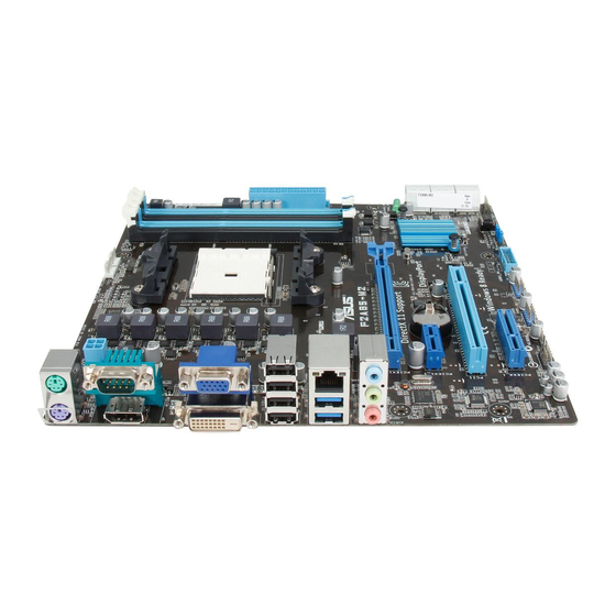
Connectors 1.8.1 Rear panel connectors PS/2 Mouse port (green). This port is for a PS/2 mouse. COM port. This port is for pointing devices or other serial devices. Video Graphics Adapter (VGA) port. This 15-pin port is for a VGA monitor or other VGA-compatible devices. - Page 35 DVI-D port. This port is for any DVI-D compatible device. DVI-D can’t be converted to output RGB Signal to CRT and isn’t compatible with DVI-I. Display port. This port connects to a high-definition digital display. PS/2 Keyboard port (purple). This port is for a PS/2 keyboard. ASUS F2A85-M2 1-23...
-
Page 36: Internal Connectors
F2A85-M2 HD-audio-compliant Legacy AC’97 pin definition compliant definition F2A85-M2 Front panel audio connector • We recommend that you connect a high-definition front panel audio module to this connector to avail of the motherboard’s high-definition audio capability. • If you want to connect a high-definition front panel audio module to this connector, set the Front Panel Type item in the BIOS setup to [HD]. - Page 37 • If you are uncertain about the minimum power supply requirement for your system, refer to the Recommended Power Supply Wattage Calculator at http://support.asus. com/PowerSupplyCalculator/PSCalculator.aspx?SLanguage=en-us for details. Speaker connector (4-pin SPEAKER) The 4-pin connector is for the chassis-mounted system warning speaker.
- Page 38 The CPU_FAN connector supports a CPU fan of maximum 2A (24 W) fan power. • Only the 4-pin CPU fan and CHA FAN can support ASUS FanXpert feature. Chassis intrusion connector (4-1 pin CHASSIS) This connector is for a chassis-mounted intrusion detection sensor or switch. Connect one end of the chassis instrusion sensor or switch cable to this connector when a chassis component is removed or replaced.
- Page 39 This connector is for the additional USB 3.0 ports. Connect the USB 3.0 bracket cable to this connector, then install the USB 3.0 bracket to the rear side of the chassis. If your chassis support customized front panel installation, with ASUS USB 3.0 header, you can have a front panel USB 3.0 solution.
- Page 40 SATA6G_4 SATA6G_1 SATA6G_2 F2A85-M2 F2A85-M2 SATA 6.0Gb/s connectors These connectors are set to AHCI mode by default. In AHCI mode, you can connect • Serial ATA boot/data hard disk drives to these connectors. If you intend to create a Serial ATA RAID set using these connectors, set the type of the SATA connectors in the BIOS to [RAID].
-
Page 41: System Panel Connector
PIN 1 F2A85-M2 HD_LED RESET F2A85-M2 System panel connector • System power LED (2-pin PLED) This 2-pin connector is for the system power LED. Connect the chassis power LED cable to this connector. The system power LED lights up when you turn on the system power, and blinks when the system is in sleep mode. -
Page 42: Onboard Leds
If an error is detected on any of these components, the corresponding LED will stay lit until the problem is resolved. DRAM_LED CPU_LED F2A85-M2 VGA_LED BOOT_DEVICE_LED F2A85-M2 CPU / DRAM / VGA / BOOT_DEVICE LED Chapter 1: Product introduction 1-30... -
Page 43: Software Support
Place the Support DVD into the optical drive. If Autorun is enabled in your computer, the DVD automatically displays the Specials screen which contains the unique features of ASUS motherboard. Click Drivers, Utilities, Make Disk, Manual, and Contact tabs to display their respective menus. - Page 44 Chapter 1: Product introduction 1-32...
-
Page 45: Bios Information
BIOS in the future. Copy the original motherboard BIOS using the ASUS Update utility. 2.1.1 ASUS Update utility The ASUS Update is a utility that allows you to manage, save, and update the motherboard BIOS in Windows environment. ®... -
Page 46: Asus Ez Flash 2
Follow the onscreen instructions to complete the updating process. 2.1.2 ASUS EZ Flash 2 The ASUS EZ Flash 2 feature allows you to update the BIOS without using an OS-based utility. Before you start using this utility, download the latest BIOS file from the ASUS website at www.asus.com. -
Page 47: Asus Crashfree Bios 3 Utility
2.1.3 ASUS CrashFree BIOS 3 utility The ASUS CrashFree BIOS 3 is an auto recovery tool that allows you to restore the BIOS file when it fails or gets corrupted during the updating process. You can restore a corrupted BIOS file using the motherboard support DVD or a USB flash drive that contains the updated BIOS file. -
Page 48: Asus Bios Updater
2.1.4 ASUS BIOS Updater The ASUS BIOS Updater allows you to update BIOS in DOS environment. This utility also allows you to copy the current BIOS file that you can use as a backup when the BIOS fails or gets corrupted during the updating process. -
Page 49: Updating The Bios File
Ensure to load the BIOS default settings to ensure system compatibility and stability. Select the Load Optimized Defaults item under the Exit menu. Refer to section 2.9 Exit menu for details. • Ensure to connect all SATA hard disk drives after updating the BIOS file if you have disconnected them. ASUS F2A85-M2... -
Page 50: Bios Setup Program
The BIOS setup screens shown in this section are for reference purposes only, and may not exactly match what you see on your screen. Visit the ASUS website at www.asus.com to download the latest BIOS file for this • motherboard. -
Page 51: Main Menu
RAM to clear the BIOS password. See section 1.7 Jumpers for information on how to erase the RTC RAM. The Administrator or User Password items on top of the screen show the default • Not Installed. After you set a password, these items show Installed. ASUS F2A85-M2... -
Page 52: Administrator Password
Administrator Password If you have set an administrator password, we recommend that you enter the administrator password for accessing the system. Otherwise, you might be able to see or change only selected fields in the BIOS setup program. To set an administrator password: Select the Administrator Password item and press <Enter>. -
Page 53: Ai Tweaker Menu
<-> keys to adjust the value. To restore the default setting, type [auto] using the keyboard and press <Enter>. Changing the values in this menu may cause the system to become unstable! If this happens, revert to the default settings. ASUS F2A85-M2... -
Page 54: Advanced Menu
Advanced menu The Advanced menu items allow you to change the settings for the CPU and other system devices. Be cautious when changing the settings of the Advanced menu items. Incorrect field values can cause the system to malfunction. 2.5.1 Trusted Computing This item appears only when a TPM module is connected to the motherboard and allows you to change TPM settings. -
Page 55: Sata Configuration
S.M.A.R.T. Status Check [Enabled] S.M.A.R.T. (Self-Monitoring, Analysis and Reporting Technology) is a monitor system. When read/write of your hard disk errors occur, this feature allows the hard disk to report warning messages during the POST. Configuration options: [Enabled] [Disabled] ASUS F2A85-M2 2-11... -
Page 56: Alert Specification Format (Asf) Configuration
2.5.4 Alert Specification Format (ASF) Configuration The Alert Specification Format (ASF 2.0) defines remote and alert settings in PCs that do not have an OS and are maintained through the network. ASF Support [Enabled] Enables or disables ASF Support. Configuration options: [Enabled] [Disabled] ASF BIOS Mode [ON] Manages ASF BIOS mode. -
Page 57: Usb Configuration
Enables the support for operating systems without an EHCI hand-off feature. [Disabled] Disables the function. USB Single Port Control Allows you to enable/disable individual USB ports. USB3_1~4, USB1~8 [Enabled] [Enabled] Enables USB3_1~4, USB1~8 [Disabled] Enables USB3_1~4, USB1~8 ASUS F2A85-M2 2-13... -
Page 58: Nb Configuration
2.5.7 NB Configuration IGFX Multi-Monitor [Disabled] Enables or disables the Internal Graphics Device Multi-Monitor support for add-on VGA devices. And the memory size of Internal Graphics Device will keep memory reserved. Configuration options: [Disabled] [Enabled] Primary Video Device [PCIE / PCI Video] Selects the primary display device. -
Page 59: Apm
Sets the Ctrl+Esc key on the PS/2 keyboard to turn on the system. [Power Key] Sets Power key on the PS/2 keyboard to turn on the system. This feature requires an ATX power supply that provides at least 1A on the +5VSB lead. ASUS F2A85-M2 2-15... - Page 60 Power On By PS/2 Mouse [Disabled] [Disabled] Disables the Power On by a PS/2 mouse. [Enabled] Enables the Power On by a PS/2 mouse. This feature requires an ATX power supply that provides at least 1A on the +5VSB lead. Power On By PME [Disabled] [Disabled] Disables the PME to wake up by PCI/PCIE devices.
-
Page 61: Serial Port Console Redirection
[None] [Hardware RTS/CTS] VT UTF8 Combo Key Support [Enabled} Enables or disables VT-UTF8 combination key support for ANSI/VT100 terminals. Configuration options: [Enabled] [Disabled] Recorder Mode [Disabled] Disables or enables text mode to capture Terminal data. Configuration options: [Enabled] [Disabled] ASUS F2A85-M2 2-17... -
Page 62: Network Stack
Legacy OS Redirection Resolution [80x25] Sets the number of rows and columns supported in a legacy OS. Configuration options: [80x25] [80x24] Putty KeyPad [VT100] Selects FunctionKey and Keypad on Putty. Configuration options: [VT100] [Linux] [XTERMR6] [SCO] [ESCN] [VT400] Redirection After BIOS POST [Always Enable] This setting specifies if BootLoader is loaded before booting to a Legacy OS. -
Page 63: Boot Menu
Accelerates the boot up speed after AC Power Loss. 2.6.2 Full Screen Logo [Enabled] [Enabled] Enables the full screen logo display feature. [Disabled] Disables the full screen logo display feature. Set this item to [Enabled] to use the ASUS MyLogo 2™ feature. ASUS F2A85-M2 2-19... -
Page 64: Post Delay Time [3 Sec]
Post Report [5 sec] This item appears only when the Full Screen Logo item is set to [Disabled] and allows you to set the waiting time for the system to display the post report. Configuration options: [1 sec] [2 sec] [3 sec] [4 sec] [5 sec] [6 sec] [7 sec] [8 sec] [9 sec] [10 sec] [Until Press ESC] 2.6.3 Post Delay Time [3 sec] Allows you to set the Post Logo Delay Time. -
Page 65: Secure Boot
Configuration options: [OK] Load DB from File Configuration options: [OK] Copy DB to File Configuration options: [OK] Delete the DB Configuration options: [Yes] [No] Append DB from File Configuration options: [OK] Load DBX from File Configuration options: [OK] ASUS F2A85-M2 2-21... -
Page 66: Boot Option Priorities
• To select the boot device during system startup, press <F8> when ASUS Logo appears. • To access Windows OS in Safe Mode, press <F8> after POST. -
Page 67: Monitor Menu
Use the <+> and <-> keys to adjust the maximum CPU fan duty cycle. The values range from 40% to 100%. When the CPU temperature reaches the upper limit, the CPU fan will operate at the maximum duty cycle. ASUS F2A85-M2 2-23... -
Page 68: Cha_Fan 1/2 Q-Fan Control [Enabled]
Fan Lower Temperature [20] Displays the lower limit of the CPU temperature. Fan Min. Duty Cycle(%) [20] Use the <+> and <-> keys to adjust the minimum CPU fan duty cycle. The values range from 20% to 100%. When the CPU temperature is under 20ºC, the CPU fan will operate at the minimum duty cycle. -
Page 69: Cpu Voltage, 3.3V Voltage, 5V Voltage, 12V Voltage
The onboard hardware monitor automatically detects the voltage output through the onboard voltage regulators. Select Ignore if you do not want to detect this item. 2.7.6 Anti Surge Support [Enabled] This item allows you to enable or disable the Anti Surge function. Configuration options: [Disabled] [Enabled] ASUS F2A85-M2 2-25... -
Page 70: Tools Menu
<Enter> to display the submenu. 2.8.1 ASUS EZ Flash 2 Utility Allows you to run ASUS EZ Flash 2. Press [Enter] to launch the ASUS EZ Flash 2 screen. For more details, see section 2.1.2 ASUS EZ Flash 2. 2.8.2... -
Page 71: Appendices
The use of shielded cables for connection of the monitor to the graphics card is required to assure compliance with FCC regulations. Changes or modifications to this unit not expressly approved by the party responsible for compliance could void the user’s authority to operate this equipment. ASUS F2A85-M2... -
Page 72: Canadian Department Of Communications Statement
IC: Canadian Compliance Statement Complies with the Canadian ICES-003 Class B specifications. This device complies with RSS 210 of Industry Canada. This Class B device meets all the requirements of the Canadian interference-causing equipment regulations. This device complies with Industry Canada license exempt RSS standard(s). Operation is subject to the following two conditions: (1) this device may not cause interference, and (2) this device must accept any interference, including interference that may cause undesired operation of the device. - Page 73 ASUS Recycling/Takeback Services ASUS recycling and takeback programs come from our commitment to the highest standards for protecting our environment. We believe in providing solutions for you to be able to responsibly recycle our products, batteries, other components as well as the packaging materials.
-
Page 74: Asus Contact Information
+1-812-282-3777 +1-510-608-4555 Web site usa.asus.com Technical Support Telephone +1-812-282-2787 Support fax +1-812-284-0883 Online support support.asus.com ASUS COMPUTER GmbH (Germany and Austria) Address Harkort Str. 21-23, D-40880 Ratingen, Germany +49-2102-959911 Web site www.asus.de Online contact www.asus.de/sales Technical Support Telephone +49-1805-010923* Support Fax... - Page 75 ASUS F2A85-M2...
- Page 76 Appendices...