HP SN6000B Hardware Reference Manual
16gb 48-port fibre channel switch
Hide thumbs
Also See for SN6000B:
- Release note (25 pages) ,
- Quick start instructions (8 pages) ,
- Reference manual (70 pages)
Table of Contents
Advertisement
HP SN6000B 16Gb 48-port Fibre Channel
Switch Hardware Reference Guide
Abstract
This document provides information on installing, configuring, and maintaining the HP SN6000B FC Switch. It is intended for
system administrators and technicians with knowledge of SANs and HP FC switches.
HP Part Number: 5697-0913
Published: September 201 1
Edition: 1
Advertisement
Table of Contents

Related Manuals for HP SN6000B


Summary of Contents for HP SN6000B
- Page 1 HP SN6000B 16Gb 48-port Fibre Channel Switch Hardware Reference Guide Abstract This document provides information on installing, configuring, and maintaining the HP SN6000B FC Switch. It is intended for system administrators and technicians with knowledge of SANs and HP FC switches. HP Part Number: 5697-0913...
- Page 2 © Copyright 201 1 Hewlett-Packard Development Company, L.P. © Copyright 201 1 Brocade Communications Systems, Incorporated Confidential computer software. Valid license from HP required for possession, use or copying. Consistent with FAR 12.21 1 and 12.212, Commercial Computer Software, Computer Software Documentation, and Technical Data for Commercial Items are licensed to the U.S. Government under vendor's standard commercial license.
-
Page 3: Table Of Contents
Nonport side of the switch......................8 HP B-series Fabric OS Native and AG modes................8 Software options........................9 ISL Trunking.........................9 Hardware options........................10 SFP transceivers.........................11 2 HP SN6000B 16Gb FC Switch installation and configuration......12 Accessories..........................12 Installation and safety considerations..................12 Electrical considerations......................12 Environmental considerations....................12 Cabling considerations.......................12 Installation..........................13... - Page 4 Diagnostic tests........................31 Switch management........................31 4 Removal and replacement of power supplies and fans........33 Removing and replacing a power supply and fan assembly............33 Determining the status of a power supply and fan assembly.............33 Removing a power supply and fan assembly.................34 Replacing a power supply and fan assembly.................35 5 Support and other resources..............36 HP technical support.......................36 Subscription service......................36...
- Page 5 Laser compliance notices......................47 English laser notice......................47 Dutch laser notice......................47 French laser notice......................48 German laser notice......................48 Italian laser notice......................48 Japanese laser notice......................49 Spanish laser notice......................49 Recycling notices........................49 English recycling notice......................49 Bulgarian recycling notice....................49 Czech recycling notice......................50 Danish recycling notice.......................50 Dutch recycling notice......................50 Estonian recycling notice.....................50 Finnish recycling notice.......................50 French recycling notice.......................50...
-
Page 6: Hp Sn6000B 16Gb Fc Switch
For descriptions of acronyms and abbreviations used in this guide, see the “Glossary”. Overview The HP SN6000B 16Gb FC Switch is a 48-port autosensing 4, 8, or 16 Gb/s as well as 10 Gb/s FC switch that delivers the latest HP single-chip architecture for FC SANs. The SN6000B 16Gb... -
Page 7: Platform Components
FICON, FICON Cascading, and FICON CUP ready. ISL Trunking (licensable), which allows up to eight ports (at 4, 8, or 16 Gb/s) between a pair of switches combined to form a single, logical ISL with a speed of up to 128 Gb/s (256 Gb/s full duplex) for optimal bandwidth utilization and load balancing. -
Page 8: Port Side Of The Switch
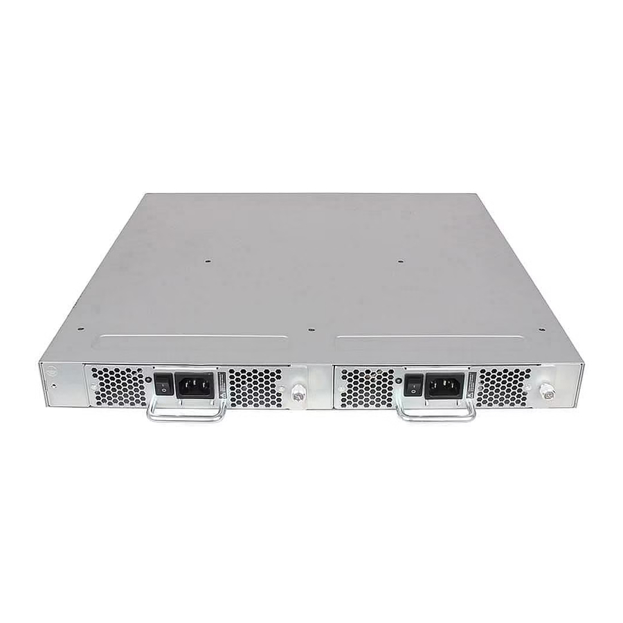
Nonport side of the switch Figure 2 (page 8) shows the nonport side of the SN6000B 16Gb FC Switch, which contains two power supply and fan assemblies (each including an AC power receptacle and AC power switch). Figure 2 Nonport side of the SN6000B 16Gb FC Switch 1. -
Page 9: Software Options
HP ISL Trunking is optional software that allows you to create trunking groups of ISLs between adjacent switches. Up to eight FC ports on the HP SN6000B 16Gb FC Switch can be used as a trunking group to achieve speeds of up to 128 Gb/s (256 Gb/s full duplex) for optimal bandwidth utilization and load balancing. -
Page 10: Hardware Options
QK732A HP Premier Flex LC/LC OM4 2f 1m Cbl QK733A HP Premier Flex LC/LC OM4 2f 2m Cbl QK734A HP Premier Flex LC/LC OM4 2f 5m Cbl QK735A HP Premier Flex LC/LC OM4 2f 15m Cbl HP SN6000B 16Gb FC Switch... -
Page 11: Sfp Transceivers
Table 1 Optional hardware kits (continued) Hardware kit Part number QK736A HP Premier Flex LC/LC OM4 2f 30m Cbl QK737A HP Premier Flex LC/LC OM4 2f 50m Cbl NOTE: For the latest information on supported hardware components, see the B-series Switches section of the HP Storage Networking website: http://www.hp.com/go/san. -
Page 12: Hp Sn6000B 16Gb Fc Switch Installation And Configuration
This chapter provides installation and configuration information for the HP SN6000B 16Gb FC Switch. Accessories The following items are included with the standard shipment of a fully-configured SN6000B 16Gb FC Switch. When you open the packages, verify that the following items are included and that no damage has occurred during shipping:... -
Page 13: Installation
Do not use tie wraps on fiber optic cables. The wraps are easily overtightened and can damage the optical fibers. Installation This section provides instructions for installing the HP SN6000B 16Gb FC Switch. Items required for installation To set up the switch for the first time, you will need the following:... -
Page 14: Installing The Switch In A Rack Using The Rack Mount Kit
Installing the switch in a rack using the Rack Mount Kit Use the SN6000B Switch Rack Mount Kit to install the switch in an HP 10000 Series Rack. CAUTION: Install the Rack Mount Kit as described in this section so that when the switch is installed, the port side faces the rear of the rack. - Page 15 Figure 5 Installing the rear mounting brackets Attach each outer rail as shown in Figure 6 (page 15). The rails are labeled Left and Right to designate the left side and right side of the rack as viewed from the front of the cabinet. Figure 6 Attaching the outer rails Slide each rail over the rear mounting brackets.
- Page 16 Ensure that the power cords do not come in contact with any sharp edges. Figure 8 Connecting power and installing the plenum 1. Cutouts for power cords 3. Power switches 2. Power cable plugs 4. Plenum HP SN6000B 16Gb FC Switch installation and configuration...
- Page 17 Connect the power cords to power sources on separate circuits to protect against AC failure. Ensure that the cords have a minimum service loop of 6 inches available and are routed to avoid stress. Power on the power supplies by setting both power switches to the ON (I) position. The power supply LEDs are amber until the POST is complete, and then change to green.
-
Page 18: Installing A Standalone Switch
If you are using static IP addressing, you will need the following items (they are not required if you are using DHCP): Fixed IP address (IPv4 or IPv6) for the switch ◦ Subnet mask value ◦ ◦ Default gateway value HP SN6000B 16Gb FC Switch installation and configuration... -
Page 19: Connecting The Serial Cable
Connecting the serial cable Connect the serial cable to the serial port on the switch and to an RS-232 serial port on the workstation. If the serial port is RJ-45 instead of RS-232, remove the adapter on the end of the serial cable and insert the exposed RJ-45 connector into the RJ-45 serial port on the workstation. - Page 20 Close the latching bail if there is one. Figure 12 Inserting an SFP+ transceiver with no pull tab in an FC port Figure 13 Inserting a 16 Gb/s SFP+ transceiver in an FC port HP SN6000B 16Gb FC Switch installation and configuration...
-
Page 21: Setting Switch Features
Connect the FC cables from the switch to your host and storage devices. Ensure that the physical connections match the connections displayed on the Device Connection window. Remove the plastic protector caps from the FC cable ends (if there are any) and position the cable connector so that it is oriented correctly. -
Page 22: Setting The Date And Time
The tstimezone --interactive command displays all time zones supported in the firmware. The timeZone_fmt command sets the time zone based on the country and city, or a time zone ID, such as PST, that you enter. This command requires administrator privileges. HP SN6000B 16Gb FC Switch installation and configuration... -
Page 23: Synchronizing Local Time
The time zone setting has the following characteristics: Automatically adjusts for Daylight Savings Time. Changing the time zone updates the local time zone setup and is reflected in local time calculations. By default, switches are in the GMT time zone (0,0). If all switches in a fabric are in one time zone, you can keep the time zone setup at the default setting. -
Page 24: Synchronizing Local Time Using Ntp
Using Telnet, log in to the switch as admin. Use the chassisname command to change the chassis name. The following example shows how to change the chassis name to myhpchassis: switch:admin> chassisname myhpchassis switch:admin> chassisname myhpchassis HP SN6000B 16Gb FC Switch installation and configuration... -
Page 25: Verifying The Configuration
Use the switchname command to change the switch name. The following example shows how to change the switch name to myhpswitch: switch:admin> switchname myhpswitch switch:admin> switchname myhpswitch Verifying the configuration To confirm that the switch is configured and ready for use: Observe the LEDs to verify that all components are functional. -
Page 26: Disabling And Enabling Ag Mode
Failback are removed automatically. When the switch reboots, it starts in Native mode. For instructions on adding the switch back to the core fabric, see the Access Gateway Administrator’s Guide. To disable AG mode using HP B-series Fabric OS commands: HP SN6000B 16Gb FC Switch installation and configuration... - Page 27 Enter the switchshow command to verify the switch mode. AG Mode is displayed if the switch is in AG mode. Interopmode 0 or Native is displayed if the switch is in Native mode. Enter the switchdisable command to disable the switch. The switch must be disabled in order to enable or disable AG mode.
-
Page 28: Hp Sn6000B 16Gb Fc Switch Operation
3 HP SN6000B 16Gb FC Switch operation This chapter discusses switch power, LEDs, maintenance, and management. Powering the switch on and off Power switches are located on the nonport side of the switch. If the switch is mounted in a rack, you must remove the plenum to access the power switches. - Page 29 Table 3 Port side LED patterns LED name LED color Status of hardware Recommended action System power No light System is off or there is an internal Verify that the system is powered on (power (green) power supply failure. supply switches set to I), the power cables are attached, and the power source is live.
-
Page 30: Post And Boot Specifications
Telnet session or access the switch through another management tool. If this does not solve the problem, the switch did not complete POST successfully. Contact your switch supplier for repair. HP SN6000B 16Gb FC Switch operation... -
Page 31: Boot
Diagnostic tests can temporarily lock the transmit and receive speed of the links. NOTE: HP does not support 2Gb connectivity to the SN6000B switch. For information about specific diagnostic tests, see the HP B-series Fabric OS Troubleshooting and Diagnostics Guide. - Page 32 (over HBA only) See the Fabric OS Administrator’s Guide and the Fabric OS 7.0.0 Command Reference Manual. Network Advisor (option to purchase) Ethernet or serial connection IP over FC See the Brocade Network Advisor documentation set. HP SN6000B 16Gb FC Switch operation...
-
Page 33: Removal And Replacement Of Power Supplies And Fans
4 Removal and replacement of power supplies and fans The power supply and fan assembly is the only FRU in the switch. You do not need special tools to remove and replace this FRU. The switch will continue to operate during the FRU replacement if you follow the procedures in this chapter. -
Page 34: Removing A Power Supply And Fan Assembly
Power Supply #2 is OK V10541, TQ2H0000189 ,60-0300031-01,X3, ,SP640-2P ,A ,TQ2H0000 br6510:admin> Removing a power supply and fan assembly The following items are required: New power supply and fan assembly #1 Phillips screwdriver To remove a power supply and fan assembly (Figure 17 (page 34)): If the switch is rack mounted, remove the plenum. -
Page 35: Replacing A Power Supply And Fan Assembly
Replacing a power supply and fan assembly To replace the power supply and fan assembly: Ensure that the replacement FRU AC power switch is in the off (O) position. CAUTION: Damage to the switch can result if the AC power switch is in the on (|) position when the switch is installed in the chassis. -
Page 36: Support And Other Resources
5 Support and other resources HP technical support For worldwide technical support information, see the HP support website: http://www.hp.com/support Before contacting HP, collect the following information: Product model names and numbers Technical support registration number (if applicable) Product serial numbers Error messages Operating system type and revision level Detailed questions... -
Page 37: Hp Websites
HP websites For additional information, see the following HP websites: http://www.hp.com http://www.hp.com/go/storage http://www.hp.com/service_locator http://www.hp.com/support/manuals http://www.hp.com/support/downloads Rack stability Rack stability protects personnel and equipment. WARNING! To reduce the risk of personal injury or damage to equipment: Extend leveling jacks to the floor. Ensure that the full weight of the rack rests on the leveling jacks. -
Page 38: Typographic Conventions
Typographic conventions Table 6 Document conventions Convention Element Blue text: Table 6 (page 38) Cross-reference links and email addresses Blue, underlined text: http://www.hp.com Website addresses Bold text Keys that are pressed Text entered into a GUI element, such as a box GUI elements that are clicked or selected, such as menu and list items, buttons, tabs, and check boxes Italic text... -
Page 39: A Specifications
A Specifications This appendix provides switch specifications. Physical specifications Table 7 Physical specifications Dimension Value Height 1U or 4.3 cm (1.7 in) Depth (without plenum) 44.3 cm (17.4 in) Width (The slightly increased width requires a slim rail 43.8 cm (17.2 in) rack mount kit for mounting.) Weight (with two power supply and fan assemblies, and 9.2 kg (20.2 lb) -
Page 40: Environmental Requirements
Table 9 Power supply specifications (continued) Specification Values the form of AC cycles, or multiple AC cycles greater than 10 ms and less than 150 ms, must not exceed 15 A peak. Single power supply output 150 W at 12 VDC Maximum current 12.5 A at 12 VDC Input line protection... -
Page 41: Data Transmission Ranges
SFP+ models, and are able to autonegotiate to the maximum link speed. NOTE: HP does not support 2 Gb/s connectivity to the SN6000B switch. Serial port specifications The serial port is located on the port side of the switch and uses an RJ-45 connector for the serial port. -
Page 42: Ag Default Port Mapping
Table 14 Serial cable pinouts Signal Description Not supported Not supported UART1_TXD Transmit data Logic ground Logic ground UART1_RXD Receive data Not supported Not supported AG default port mapping Table 15 (page 42) lists the port mappings of F_Ports to N_Ports. Table 15 AG default port mapping Total ports F_Ports... -
Page 43: B Regulatory Compliance Notices
B Regulatory compliance notices This appendix contains regulatory notices for the switch. Regulatory compliance identification numbers For the purpose of regulatory compliance certifications and identification, this product has been assigned a unique regulatory model number. The regulatory model number can be found on the product nameplate label, along with all required approval markings and information. -
Page 44: Declaration Of Conformity For Products Marked With The Fcc Logo, United States Only
Or call 1-281-514-3333 Modification The FCC requires the user to be notified that any changes or modifications made to this device that are not expressly approved by Hewlett-Packard Company may void the user's authority to operate the equipment. Cables When provided, connections to this device must be made with shielded cables with metallic RFI/EMI connector hoods in order to maintain compliance with FCC Rules and Regulations. -
Page 45: Japanese Notices
This compliance is indicated by the following conformity marking placed on the product: This marking is valid for non-Telecom products and EU harmonized Telecom products (e.g., Bluetooth). Certificates can be obtained from http://www.hp.com/go/certificates. Hewlett-Packard GmbH, HQ-TRE, Herrenberger Strasse 140, 71034 Boeblingen, Germany Japanese notices Japanese VCCI-A notice Japanese VCCI-B notice... -
Page 46: Korean Notices
Korean notices Class A equipment Class B equipment Taiwanese notices BSMI Class A notice Taiwan battery recycle statement Turkish recycling notice Türkiye Cumhuriyeti: EEE Yönetmeliğine Uygundur Regulatory compliance notices... -
Page 47: Vietnamese Information Technology And Communications Compliance Marking
Vietnamese Information Technology and Communications compliance marking Laser compliance notices English laser notice This device may contain a laser that is classified as a Class 1 Laser Product in accordance with U.S. FDA regulations and the IEC 60825- 1 . The product does not emit hazardous laser radiation. WARNING! Use of controls or adjustments or performance of procedures other than those specified herein or in the laser product's installation guide may result in hazardous radiation... -
Page 48: French Laser Notice
French laser notice German laser notice Italian laser notice Regulatory compliance notices... -
Page 49: Japanese Laser Notice
Japanese laser notice Spanish laser notice Recycling notices English recycling notice Disposal of waste equipment by users in private household in the European Union This symbol means do not dispose of your product with your other household waste. Instead, you should protect human health and the environment by handing over your waste equipment to a designated collection point for the recycling of waste electrical and electronic equipment. -
Page 50: Czech Recycling Notice
Czech recycling notice Likvidace zařízení v domácnostech v Evropské unii Tento symbol znamená, že nesmíte tento produkt likvidovat spolu s jiným domovním odpadem. Místo toho byste měli chránit lidské zdraví a životní prostředí tím, že jej předáte na k tomu určené sběrné pracoviště, kde se zabývají... -
Page 51: German Recycling Notice
German recycling notice Entsorgung von Altgeräten von Benutzern in privaten Haushalten in der EU Dieses Symbol besagt, dass dieses Produkt nicht mit dem Haushaltsmüll entsorgt werden darf. Zum Schutze der Gesundheit und der Umwelt sollten Sie stattdessen Ihre Altgeräte zur Entsorgung einer dafür vorgesehenen Recyclingstelle für elektrische und elektronische Geräte übergeben. -
Page 52: Polish Recycling Notice
Polish recycling notice Utylizacja zużytego sprzętu przez użytkowników w prywatnych gospodarstwach domowych w krajach Unii Europejskiej Ten symbol oznacza, że nie wolno wyrzucać produktu wraz z innymi domowymi odpadkami. Obowiązkiem użytkownika jest ochrona zdrowa ludzkiego i środowiska przez przekazanie zużytego sprzętu do wyznaczonego punktu zajmującego się... -
Page 53: Swedish Recycling Notice
Swedish recycling notice Hantering av elektroniskt avfall för hemanvändare inom EU Den här symbolen innebär att du inte ska kasta din produkt i hushållsavfallet. Värna i stället om natur och miljö genom att lämna in uttjänt utrustning på anvisad insamlingsplats. Allt elektriskt och elektroniskt avfall går sedan vidare till återvinning. -
Page 54: French Battery Notice
French battery notice German battery notice Regulatory compliance notices... -
Page 55: Italian Battery Notice
Italian battery notice Japanese battery notice Battery replacement notices... -
Page 56: Spanish Battery Notice
Spanish battery notice Regulatory compliance notices... -
Page 57: C Electrostatic Discharge And Grounding Recommendations
C Electrostatic discharge and grounding recommendations Electrostatic discharge recommendations CAUTION: To prevent damaging the system, be aware of the precautions you need to follow when setting up the system or handling parts. A discharge of static electricity from a finger or other conductor may damage system boards or other static-sensitive devices. -
Page 58: Glossary
Glossary This glossary defines acronyms and terms used in this guide or related to this product. It is not a comprehensive glossary of computer terms. Admin Domain. Access Gateway. APM. Advanced Performance Monitoring. Control Unit Port. DDR2 Double data rate 2. DHCP Dynamic Host Configuration Protocol. - Page 59 World Wide Name.
-
Page 60: Index
Subscriber's Choice, HP, symbols in text, help obtaining, Taiwanese notices, technical support technical support, HP SN6000B 16Gb FC Switch service locator website, hardware options, text symbols, software options, warning ISL trunking groups, rack stability, websites customer self repair,...