HP ProLiant DL380p User Manual
Hp proliant dl380p gen8 server user guide
Hide thumbs
Also See for ProLiant DL380p:
- User manual (134 pages) ,
- Specification (84 pages) ,
- Quickspecs (52 pages)
Table of Contents
Advertisement
HP ProLiant DL380p Gen8 Server
User Guide
Abstract
This document is for the person who installs, administers, and troubleshoots servers and storage systems. HP assumes you are qualified in the
servicing of computer equipment and trained in recognizing hazards in products with hazardous energy levels.
Part Number: 661848-001
March 2012
Edition: 1
Advertisement
Table of Contents

Related Manuals for HP ProLiant DL380p


Summary of Contents for HP ProLiant DL380p
-
Page 1: User Guide
HP ProLiant DL380p Gen8 Server User Guide Abstract This document is for the person who installs, administers, and troubleshoots servers and storage systems. HP assumes you are qualified in the servicing of computer equipment and trained in recognizing hazards in products with hazardous energy levels. - Page 2 Nothing herein should be construed as constituting an additional warranty. HP shall not be liable for technical or editorial errors or omissions contained herein. Microsoft®, Windows®, and Windows Server® are U.S. registered trademarks of Microsoft Corporation. Bluetooth is a trademark owned by its proprietor and used by Hewlett-Packard Company under license.
-
Page 3: Table Of Contents
Contents Component identification ....................... 7 Front panel components ..........................7 Front panel LEDs and buttons ......................... 8 Access the Systems Insight Display ......................... 9 Systems Insight Display LEDs ........................10 Systems Insight Display LED combinations ..................... 11 Rear panel components ..........................12 Rear panel LEDs and buttons ........................ - Page 4 Installing the server into the rack ........................36 Installing the operating system ........................38 Powering on and selecting boot options ....................... 38 Registering the server..........................39 Hardware options installation ....................... 40 Introduction ............................... 40 Processor and fan option ..........................40 Memory options ............................
- Page 5 HP ROM-Based Setup Utility ........................95 Using RBSU ............................. 95 Auto-configuration process ........................ 95 Boot options ............................ 96 Configuring AMP modes ........................96 Re-entering the server serial number and product ID ................96 Utilities and features ........................... 97 Array Configuration Utility ........................ 97 Option ROM Configuration for Arrays....................
- Page 6 HP 460 W CS HE Power Supply (92%) specifications................ 112 HP 460 W CS Platinum Power Supply (94%) specifications ..............112 HP 750 W CS HE Power Supply (92%) specifications................ 112 HP 750 W CS Platinum Power Supply (94%) specifications ..............113 HP 750 W 48V CS Power Supply specifications ................
-
Page 7: Component Identification
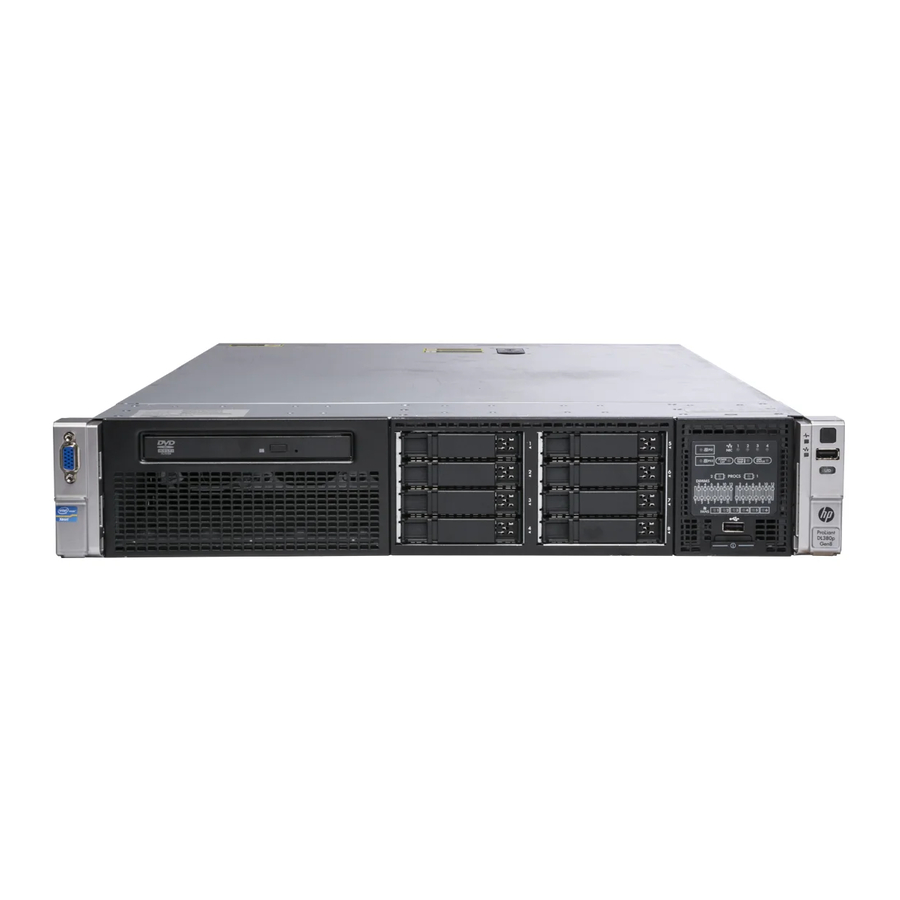
Component identification Front panel components • SFF model Item Description Video connector SATA optical drive bay Drive bays Systems Insight Display USB connectors (2) • SFF model with optional hard drive cage Item Description Video connector Drive bays (box 1) Drive bays (box 2) Systems Insight Display USB connectors (2) -
Page 8: Front Panel Leds And Buttons
• LFF model Item Description Video connector SATA optical drive bay Drive bays Systems Insight Display USB connectors (2) Front panel LEDs and buttons Item Description Status Aggregate network LED Off = No network link Solid green = Link to network Flashing green = Network activity Component identification 8... -
Page 9: Access The Systems Insight Display
Item Description Status System health LED Solid Green = Normal Flashing Amber = System degraded Flashing Red = System critical To identify components in degraded or critical state, see "Systems Insight Display LEDs (on page 10)." UID LED and button Off = Deactivated Solid Blue = Activated Flashing Blue = System being remotely managed... -
Page 10: Systems Insight Display Leds
Systems Insight Display LEDs The HP Systems Insight Display LEDs represent the system board layout. The display enables diagnosis with the access panel installed. Item Description Status Power cap Off = System is in standby, or no cap is set. Solid green = Power cap applied NIC link/activity Off = No link to network. -
Page 11: Systems Insight Display Led Combinations
Systems Insight Display LED combinations When the health LED on the front panel illuminates either amber or red, the server is experiencing a health event. Combinations of illuminated Systems Insight Display LEDs, the system power LED, and the health LED indicate system status. -
Page 12: Rear Panel Components
Rear panel components Item Description PCIe slots 1–3 (top to bottom) PCIe slots 4–6 (top to bottom) Power supply 1 (PS1) PS1 power connector PS2 power connector Power supply 2 (PS2) USB connectors (4) Video connector iLO connector Serial connector FlexLOM ports (Shown: 4x1Gb/Optional: 2x10Gb);... -
Page 13: Non-Hot-Plug Pci Riser Board Slot Definitions
Item Description Status UID LED/button Off = Deactivated Solid blue = Activated Flashing blue = System being managed remotely Power supply 2 Off = System is off or power supply has failed. Solid green = Normal Power supply 1 Off = System is off or power supply has failed. Solid green = Normal NIC activity LED Off = No network activity... -
Page 14: System Board Components
• The PCIe2 x16 riser cage supports a maximum power of 150 W with an HP power cable. This cable must be used for PCIe card wattages greater than 75 W. System board components Item Description Fan connector 6 Systems Insight Display connector Fan connector 5 Processor 1 DIMM slots Fan connector 4... -
Page 15: System Maintenance Switch
Item Description Second drive cage, box 1 power connector Fan connector 1 Discovery services connector Front video connector USB connector Power supply backplane connector SATA optical drive connector NMI jumper System battery SD card slot Secondary (processor 2) PCI riser connector System maintenance switch Processor 2 socket TPM connector... -
Page 16: Nmi Functionality
When the system maintenance switch position 6 is set to the On position, the system is prepared to erase all system configuration settings from both CMOS and NVRAM. CAUTION: Clearing CMOS and/or NVRAM deletes configuration information. Be sure to properly configure the server or data loss could occur. NMI functionality An NMI crash dump enables administrators to create crash dump files when a system is hung and not responding to traditional debug mechanisms. -
Page 17: Sas And Sata Device Numbers
SAS and SATA device numbers • SFF device bay numbering • Optional SFF device bay numbering • LFF device bay numbering Drive LED definitions Item Status Definition Locate Solid blue The drive is being identified by a host application. Component identification 17... -
Page 18: Pci Riser Cage Led
Item Status Definition Flashing blue The drive carrier firmware is being updated or requires an update. Activity ring Rotating green Drive activity No drive activity Do not remove Solid white Do not remove the drive. Removing the drive causes one or more of the logical drives to fail. -
Page 19: Fbwc Module Leds (P222, P420, P421)
FBWC module LEDs (P222, P420, P421) The FBWC module has three single-color LEDs (one amber and two green). The LEDs are duplicated on the reverse side of the cache module to facilitate status viewing. 1 - Amber 2 - Green 3 - Green Interpretation The cache module is not powered. - Page 20 CAUTION: To avoid damage to server components, fan blanks must be installed in fan bays 1 and 2 in a single-processor configuration. The only two valid fan configurations are listed in the following table. Configuration Fan bay 1 Fan bay 2 Fan bay 3 Fan bay 4 Fan bay 5 Fan bay 6 Fan blank Fan blank...
-
Page 21: Operations
Operations Power up the server To power up the server, press the Power On/Standby button. Power down the server Before powering down the server for any upgrade or maintenance procedures, perform a backup of critical server data and programs. IMPORTANT: When the server is in standby mode, auxiliary power is still being provided to the system. -
Page 22: Remove The Access Panel
After performing the installation or maintenance procedure, slide the server back into the rack, and then press the server firmly into the rack to secure it in place. WARNING: To reduce the risk of personal injury, be careful when pressing the server rail-release latches and sliding the server into the rack. -
Page 23: Install The Access Panel
To remove the component: Power down the server if performing a non-hot-plug installation or maintenance procedure ("Power down the server" on page 21). Extend the server from the rack (on page 21). Use the T-15 Torx screwdriver attached to the rear of the server to loosen the security screw on the hood latch. -
Page 24: Remove The Hot-Plug Fan Cage
Open the cable management arm. Note that the cable management arm can be right-mounted or left-mounted. Remove the hot-plug fan cage To remove the component: Power down the server (on page 21). Remove all power: Disconnect each power cord from the power source. Disconnect each power cord from the server. -
Page 25: Remove The Hot-Plug Fan
Remove the fan cage. CAUTION: Do not operate the server for long periods with the access panel open or removed. Operating the server in this manner results in improper airflow and improper cooling that can lead to thermal damage. IMPORTANT: For optimum cooling, install fans in all primary fan locations. -
Page 26: Remove The Full-Length Expansion Board
Remove the fan. CAUTION: Do not operate the server for long periods with the access panel open or removed. Operating the server in this manner results in improper airflow and improper cooling that can lead to thermal damage. IMPORTANT: For optimum cooling, install fans in all primary fan locations. For more information, refer to the fan locations table ("Hot-plug fans"... -
Page 27: Remove The Pci Riser Cage
Release the full-length expansion board retainer, and then remove the PCI riser cage. Remove the full-length expansion board. To replace the component, reverse the removal procedure. Remove the PCI riser cage CAUTION: To prevent damage to the server or expansion boards, power down the server and remove all AC power cords before removing or installing the PCI riser cage. -
Page 28: Install The Pci Riser Cage
Release the full-length expansion board retainer, and then remove the PCI riser cage. Remove the full-length expansion board. Install the PCI riser cage WARNING: To reduce the risk of personal injury, electric shock, or damage to the equipment, remove the power cord to remove power from the server. The front panel Power On/Standby button does not completely shut off system power. -
Page 29: Secure The Full-Length Expansion Board Retainer
Install the PCI riser cage. Install the access panel (on page 23). Install the server into the rack ("Installing the server into the rack" on page 36). Connect each power cord to the server. Connect each power cord to the power source. Power up the server (on page 21). -
Page 30: Remove The Air Baffle
Secure the full-length expansion board retainer. Install the access panel (on page 23). Install the server into the rack ("Installing the server into the rack" on page 36). Connect each power cord to the server. Connect each power cord to the power source. Power up the server (on page 21). - Page 31 Release the full-length expansion board retainer, and then remove the PCI riser cage. Remove the air baffle. To replace the component, reverse the removal procedure. Operations 31...
-
Page 32: Setup
Setup Optional installation services Delivered by experienced, certified engineers, HP Care Pack services help you keep your servers up and running with support packages tailored specifically for HP ProLiant systems. HP Care Packs let you integrate both hardware and software support into a single package. A number of service level options are available to meet your needs. -
Page 33: Space And Airflow Requirements
• must be a minimum of 7 cm (2.75 in). IMPORTANT: The HP ProLiant DL380p Gen8 Server cable management arm is not supported on Compaq branded 7000 series racks. Temperature requirements To ensure continued safe and reliable equipment operation, install or position the system in a well-ventilated, climate-controlled environment. -
Page 34: Power Requirements
CAUTION: To reduce the risk of damage to the equipment when installing third-party options: • Do not permit optional equipment to impede airflow around the server or to increase the internal rack temperature beyond the maximum allowable limits. Do not exceed the manufacturer’s TMRA. •... -
Page 35: Rack Warnings
WARNING: To reduce the risk of electric shock or energy hazards: • This equipment must be installed by trained service personnel, as defined by the NEC and IEC 60950-1, Second Edition, the standard for Safety of Information Technology Equipment. Connect the equipment to a reliably grounded SELV source. An SELV source is a secondary •... -
Page 36: Identifying The Contents Of The Server Shipping Carton
WARNING: To reduce the risk of personal injury or damage to the equipment, be sure that: • The leveling jacks are extended to the floor. The full weight of the rack rests on the leveling jacks. • The stabilizing feet are attached to the rack if it is a single-rack installation. •... - Page 37 WARNING: To reduce the risk of electric shock, fire, or damage to the equipment, do not plug telephone or telecommunications connectors into RJ-45 connectors. Connect the power cord to the rear of the server. Install the power cord anchors. Secure the cables to the cable management arm. IMPORTANT: When using cable management arm components, be sure to leave enough slack in each of the cables to prevent damage to the cables when the server is extended from the rack.
-
Page 38: Installing The Operating System
WARNING: To reduce the risk of electric shock or damage to the equipment: • Do not disable the power cord grounding plug. The grounding plug is an important safety feature. Plug the power cord into a grounded (earthed) electrical outlet that is easily accessible at all •... -
Page 39: Registering The Server
To modify the server configuration ROM default settings, press F9 when prompted from the start up sequence to enter the RBSU. By default, RBSU runs in the English language. If you do not need to modify the server configuration and are ready to install the system software, press F10 to access Intelligent Provisioning. -
Page 40: Hardware Options Installation
Hardware options installation Introduction If more than one option is being installed, read the installation instructions for all the hardware options and identify similar steps to streamline the installation process. WARNING: To reduce the risk of personal injury from hot surfaces, allow the drives and the internal system components to cool before touching them. - Page 41 If any full-length PCI riser boards are installed, release the full-length expansion board retainer, and then remove the PCI riser cage. Remove the air baffle (on page 30). Open the heatsink retaining bracket, and then remove the blank. CAUTION: The pins on the processor socket are very fragile. Any damage to them may require replacing the system board.
- Page 42 Open each of the processor locking levers in the order indicated, and then open the processor retaining bracket. Remove the clear processor socket cover. Retain the processor socket cover for future use. Hardware options installation 42...
- Page 43 Install the processor. Verify that the processor is fully seated in the processor retaining bracket by visually inspecting the processor installation guides on either side of the processor. THE PINS ON THE SYSTEM BOARD ARE VERY FRAGILE AND EASILY DAMAGED. CAUTION: THE PINS ON THE SYSTEM BOARD ARE VERY FRAGILE AND EASILY DAMAGED.
- Page 44 Press and hold the processor retaining bracket in place, and then close each processor locking lever. Press only in the area indicated on the processor retaining bracket. Remove the thermal interface protective cover from the heatsink. Hardware options installation 44...
- Page 45 Install the heatsink. Remove the two fan blanks. Hardware options installation 45...
- Page 46 Install the two additional fans included with the processor. You can install memory ("Installing a DIMM" on page 52) on the second processor. HP recommends balancing memory between both processors for improved performance. For more information on memory configurations, see "Memory Options (on page 47)." Install the air baffle ("Remove the air baffle"...
-
Page 47: Memory Options
Memory options IMPORTANT: This server does not support mixing LRDIMMs, RDIMMs, or UDIMMs. Attempting to mix any combination of these DIMMs can cause the server to halt during BIOS initialization. The memory subsystem in this server can support LRDIMMs, RDIMMs, or UDIMMs: •... -
Page 48: Hp Smartmemory
HP SmartMemory HP SmartMemory, introduced for Gen8 servers, authenticates and unlocks certain features available only on HP Qualified memory and verifies whether installed memory has passed HP qualification and test processes. Qualified memory is performance-tuned for HP ProLiant and BladeSystem servers and provides future enhanced support through HP Active Health and manageability software. -
Page 49: Dimm Identification
Dual- and quad-rank DIMMs provide the greatest capacity with the existing memory technology. For example, if current DRAM technology supports 8-GB single-rank DIMMs, a dual-rank DIMM would be 16 GB, and a quad-rank DIMM would be 32 GB. LRDIMMs are labeled as quad-rank DIMMs; however, they function more like dual-rank DIMMs. There are four ranks of DRAM on the DIMM, but the LRDIMM buffer creates an abstraction that allows the DIMM to appear as a dual-rank DIMM to the system. -
Page 50: Memory Configurations
For the latest supported memory information, see the QuickSpecs on the HP website (http://h18000.www1.hp.com/products/quickspecs/ProductBulletin.html). At the website, choose the geographic region, and then locate the product by name or product category. Memory configurations To optimize server availability, the server supports the following AMP modes: •... -
Page 51: General Dimm Slot Population Guidelines
Online Spare memory configuration Online spare memory provides protection against degraded DIMMs by reducing the likelihood of uncorrected memory errors. This protection is available without any operating system support. Online spare memory protection dedicates one rank of each memory channel for use as spare memory. The remaining ranks are available for OS and application use. -
Page 52: Installing A Dimm
Online spare population For online spare memory mode configurations, observe the following guidelines: • Observe the general DIMM slot population guidelines (on page 51). • Each channel must have a valid online spare configuration. • Each channel can have a different valid online spare configuration. •... -
Page 53: Hot-Plug Hard Drive Options
Install the DIMM. Install the access panel (on page 23). Install the server into the rack ("Installing the server into the rack" on page 36). Connect each power cord to the server. Connect each power cord to the power source. Power up the server (on page 21). -
Page 54: Removing A Hot-Plug Sas Or Sata Hard Drive
Remove the drive blank. Prepare the drive. Install the drive. Determine the status of the drive from the drive LED definitions (on page 17). Removing a hot-plug SAS or SATA hard drive CAUTION: For proper cooling do not operate the server without the access panel, baffles, expansion slot covers, or blanks installed. -
Page 55: Controller Options
Remove the drive. Controller options The server ships with an embedded Smart Array P420i controller. For more information about the controller and its features, see the HP Smart Array Controllers for HP ProLiant Servers User Guide on the HP website (http://bizsupport2.austin.hp.com/bc/docs/support/SupportManual/c01608507/c01608507.pdf). -
Page 56: Installing The Flash-Backed Write Cache Module
NOTE: The data protection and the time limit also apply if a power outage occurs. When power is restored to the system, an initialization process writes the preserved data to the hard drives. Installing the flash-backed write cache module CAUTION: The cache module connector does not use the industry standard DDR3 mini DIMM pinout. -
Page 57: Installing The Flash-Backed Write Cache Capacitor Pack
Connect the capacitor pack cable to the connector on the top of the cache module. Install the access panel (on page 23). Install the server into the rack ("Installing the server into the rack" on page 36). Connect each power cord to the server. Connect each power cord to the power source. - Page 58 Connect the capacitor pack cable to the connector on the top of the cache module. Install one or two FBWC capacitor packs into the FBWC capacitor pack holder. Install the FBWC capacitor pack holder into the server: Hardware options installation 58...
-
Page 59: Optical Drive Option
8 or 16 drive SFF 8 drive LFF Install the access panel (on page 23). Install the server into the rack ("Installing the server into the rack" on page 36). Connect each power cord to the server. Connect each power cord to the power source. Power up the server (on page 21). - Page 60 Disconnect each power cord from the server. Extend the server from the rack (on page 21). Remove the access panel (on page 22). Remove the existing media drive option or blank. Slide the optical drive into the drive bay. Hardware options installation 60...
-
Page 61: Redundant Hot-Plug Power Supply Option
Connect the power and data cable to the system board and the optical drive. Install the access panel (on page 23). Install the server into the rack ("Installing the server into the rack" on page 36). Connect each power cord to the server. Connect each power cord to the power source. -
Page 62: Flexlom Option
Insert the power supply into the power supply bay until it clicks into place. Connect the power cord to the power supply. Route the power cord. Use best practices when routing power cords and other cables. A cable management arm is available to help with routing. To obtain a cable management arm, contact an HP authorized reseller. - Page 63 Remove any attached network cables. Extend the server from the rack (on page 21). Remove the access panel (on page 22). Loosen the thumbscrew. Remove the existing FlexLOM. Install the component: Firmly seat the FlexLOM in the slot. Tighten the thumbscrew. Install the access panel (on page 23).
-
Page 64: Expansion Board Options
Connect each power cord to the power source. Power up the server (on page 21). Expansion board options The server supports PCI Express expansion boards. The server ships with PCIe riser boards and expansion slots. PCIe expansion boards are supported with optional riser boards. Removing the expansion slot blanks CAUTION: To prevent damage to the server or expansion boards, power down the server and... -
Page 65: Installing A Half-Length Expansion Board
Remove the expansion slot blank. To replace the component, reverse the removal procedure. Installing a half-length expansion board Power down the server (on page 21). Remove all power: Disconnect each power cord from the power source. Disconnect each power cord from the server. Extend the server from the rack (on page 21). -
Page 66: Installing A Full-Length Expansion Board
Install the PCI riser cage (on page 28). Install the access panel (on page 23). Install the server into the rack ("Installing the server into the rack" on page 36). Connect each power cord to the server. Connect each power cord to the power source. Power up the server (on page 21). -
Page 67: Secondary Pci Riser Cage Option
Power up the server (on page 21). Secondary PCI riser cage option WARNING: To reduce the risk of personal injury, electric shock, or damage to the equipment, remove the power cord to remove power from the server. The front panel Power On/Standby button does not completely shut off system power. - Page 68 Remove the blank from the optional secondary PCI riser cage. Install an expansion board into the PCI riser cage. Hardware options installation 68...
-
Page 69: Hard Drive Cage Option
Install the optional secondary PCI riser cage. If not already installed, install the secondary processor ("Processor and fan option" on page 40). Install the access panel (on page 23). Install the server into the rack ("Installing the server into the rack"... - Page 70 Release the full-length expansion board retainer, and then remove the PCI riser cage. Remove the air baffle. Hardware options installation 70...
- Page 71 Remove the fan cage. Disconnect and remove the optical drive cable, if installed. Hardware options installation 71...
- Page 72 Using a T-15 Torx screwdriver, remove the two optical drive retaining screws, and then remove the optical drive cage. Install the optional hard drive cage. Install the hard drives and hard drive blanks. Hardware options installation 72...
- Page 73 To access the cables, remove the fan bracket on the right side of the chassis. Connect the cables: Connect one end of the power cable to the SAS backplane and the other end to the power connector on the system board. Hardware options installation 73...
- Page 74 Remove the existing SAS cable from the cable guide and from the system board. Connect the end of each SAS signal cable to the SAS backplane, and then route the SAS signal cables behind the cable guide. Do not connect the other ends yet. Hardware options installation 74...
- Page 75 Install the fan bracket. Be sure that the cables are properly routed in the channel along the fan bracket. Remove the blank from the PCI riser cage. Hardware options installation 75...
- Page 76 Install the SAS controller board into the PCI riser cage. Install the fan cage. Install the air baffle. Hardware options installation 76...
- Page 77 If you do not have a full-length expansion board, the air baffle can be installed last. Connect the other end of the SAS signal cables to the SAS controller board and to the system board. Then, install the PCI riser cage. SAS cables can be connected to the PCI riser cage and the system board before or after the PCI riser cage is installed.
-
Page 78: 2U Rack Bezel Option
Completed SAS cabling: Make sure any installed full-length expansion boards are seated in the retainer clip on the air baffle. Install the access panel (on page 23). Install the server into the rack. Connect each power cord to the server. Connect each power cord to the power source. -
Page 79: Hp Trusted Platform Module Option
Install the 2U rack bezel into the chassis, and then lock the 2U rack bezel with the key. HP Trusted Platform Module option Use these instructions to install and enable a TPM on a supported server. This procedure includes three sections: Installing the Trusted Platform Module board. -
Page 80: Installing The Trusted Platform Module Board
• HP is not liable for blocked data access caused by improper TPM use. For operating instructions, see the encryption technology feature documentation provided by the operating system. Installing the Trusted Platform Module board WARNING: To reduce the risk of personal injury, electric shock, or damage to the equipment, remove the power cord to remove power from the server. -
Page 81: Retaining The Recovery Key/Password
Install the TPM security rivet by pressing the rivet firmly into the system board. Install the air baffle. Install the PCI riser cage (on page 28). Install the access panel (on page 23). Install the server into the rack ("Installing the server into the rack"... - Page 82 Press the Esc key to exit the current menu, or press the F10 key to exit RBSU. Reboot the server. Enable the TPM in the OS. For OS-specific instructions, see the OS documentation. CAUTION: When a TPM is installed and enabled on the server, data access is locked if you fail to follow the proper procedures for updating the system or option firmware, replacing the system board, replacing a hard drive, or modifying OS application TPM settings.
-
Page 83: Cabling
Cabling SAS hard drive cabling • SFF hard drive cabling: • SFF cabling, with optional drive cage: Cabling 83... -
Page 84: Optical Drive Cabling
• LFF hard drive cabling: Optical drive cabling Cabling 84... -
Page 85: Fbwc Cabling
FBWC cabling • 8 or 16 drive SFF • 8 drive LFF • PCIe option Cabling 85... -
Page 86: Chipset Sata Cable Option
Depending on the server configuration, you may need to remove the primary PCI riser cage ("Remove the PCI riser cage" on page 27) before cabling to a PCIe expansion board. Chipset SATA cable option With the chipset SATA cable option, the chipset SATA controller can be used with a single SATA hard drive that is installed in one hard drive bay of the SFF or LFF hard drive cage. - Page 87 WARNING: Eliminate the risk of electric shock by removing all AC power from the system before installing or replacing any non-hot-plug hardware option. Disconnect all power cords to completely remove power from the server. WARNING: To reduce the risk of personal injury from hot surfaces, allow the drives and the internal system components to cool before touching them.
- Page 88 Disconnect the SATA cable from the optical drive and the SATA connector on the system board. The optical bay is disabled with the chipset SATA cable option. Connect the chipset SATA cable: Connect the chipset SATA cable connector to the chipset SATA controller port on the system board. The chipset SATA connector on the SATA cable is narrower than the chipset SATA controller port header on the system board.
-
Page 89: 150W Pcie Power Cable Option
Install the server in the rack ("Installing the server into the rack" on page 36). Remove any installed hard drives ("Removing a hot-plug SAS or SATA hard drive" on page 54). Install a SATA hard drive ("Installing a hot-plug SAS or SATA hard drive"... -
Page 90: Software And Configuration Utilities
Software and configuration utilities Server mode The software and configuration utilities presented in this section operate in online mode, offline mode, or in both modes. Software or configuration utility Server mode Online and Offline HP iLO (on page 90) Online and Offline Active Health System (on page 91) Online and Offline Integrated Management Log (on page 92) -
Page 91: Active Health System
HP iLO enables and manages the Active Health System (on page 91) and also features Agentless Management. All key internal subsystems are monitored by HP iLO. SNMP alerts are sent directly by HP iLO regardless of the host operating system or even if no host operating system is installed. Using HP iLO, you can do the following: •... -
Page 92: Intelligent Provisioning
The Active Health System log, in conjunction with the system monitoring provided by Agentless Management or SNMP Pass-thru, provides continuous monitoring of hardware and configuration changes, system status, and service alerts for various server components. The Agentless Management Service is available in the SPP, which is a disk image (.iso) that you can download from the HP website (http://www.hp.com/go/spp/download). -
Page 93: Hp Insight Diagnostics
HP Insight Diagnostics HP Insight Diagnostics is a proactive server management tool, available in both offline and online versions, that provides diagnostics and troubleshooting capabilities to assist IT administrators who verify server installations, troubleshoot problems, and perform repair validation. HP Insight Diagnostics Offline Edition performs various in-depth system and component testing while the OS is not running. -
Page 94: Scripting Toolkit
Scripting Toolkit The Scripting Toolkit is a server deployment product that enables you to build an unattended automated installation for high-volume server deployments. The Scripting Toolkit is designed to support ProLiant BL, ML, DL, and SL servers. The toolkit includes a modular set of utilities and important documentation that describes how to apply these tools to build an automated server deployment process. -
Page 95: Hp Rom-Based Setup Utility
• Enables direct update of BMC firmware (HP iLO) For more information about HP SUM and to access the HP Smart Update Manager User Guide, see the HP website (http://www.hp.com/go/hpsum/documentation). HP ROM-Based Setup Utility RBSU is a configuration utility embedded in ProLiant servers that performs a wide range of configuration activities that can include the following: •... -
Page 96: Boot Options
NOTE: The server may not support all the following examples. Drives installed Drives used RAID level RAID 0 RAID 1 3, 4, 5, or 6 RAID 5 3, 4, 5, or 6 None More than 6 To change any ORCA default settings and override the auto-configuration process, press the F8 key when prompted. -
Page 97: Utilities And Features
WARNING! WARNING! WARNING! The serial number is loaded into the system during the manufacturing process and should NOT be modified. This option should only be used by qualified service personnel. This value should always match the serial number sticker located on the chassis. Warning: The serial number should ONLY be modified by qualified service personnel. -
Page 98: Option Rom Configuration For Arrays
ACU is now available as an embedded utility, starting with HP ProLiant Gen8 servers. To access ACU, use one of the following methods: • If an optional controller is not installed, press F10 during boot. • If an optional controller is installed, when the system recognizes the controller during POST, press F5. For optimum performance, the minimum display settings are 1024 ×... -
Page 99: Automatic Server Recovery
For more information, see the Download drivers and software page for the server. To access the server-specific page, enter the following web address into the browser: http://www.hp.com/support/<servername> For example: http://www.hp.com/support/dl360g6 Automatic Server Recovery ASR is a feature that causes the system to restart when a catastrophic operating system error occurs, such as a blue screen, ABEND (does not apply to HP ProLiant DL980 Servers), or panic. -
Page 100: Keeping The System Current
Keeping the system current Drivers IMPORTANT: Always perform a backup before installing or updating device drivers. The server includes new hardware that may not have driver support on all OS installation media. If you are installing an Intelligent Provisioning-supported OS, use Intelligent Provisioning (on page 92) and its Configure and Install feature to install the OS and latest supported drivers. -
Page 101: Hp Operating Systems And Virtualization Software Support For Proliant Servers
HP Operating Systems and Virtualization Software Support for ProLiant Servers For information about specific versions of a supported operating system, see the HP website (http://www.hp.com/go/ossupport). HP Technology Service Portfolio HP Technology Services offers a targeted set of consultancy, deployment, and service solutions designed to meet the support needs of the most business and IT environments. -
Page 102: Troubleshooting
Troubleshooting Troubleshooting resources The HP ProLiant Gen8 Troubleshooting Guide, Volume I: Troubleshooting provides procedures for resolving common problems and comprehensive courses of action for fault isolation and identification, issue resolution, and software maintenance on ProLiant servers and server blades. To view the guide, select a language: •... -
Page 103: Battery Replacement
Battery replacement If the server no longer automatically displays the correct date and time, you may need to replace the battery that provides power to the real-time clock. WARNING: The computer contains an internal lithium manganese dioxide, a vanadium pentoxide, or an alkaline battery pack. A risk of fire and burns exists if the battery pack is not properly handled. -
Page 104: Regulatory Compliance Notices
Regulatory compliance notices Regulatory compliance identification numbers For the purpose of regulatory compliance certifications and identification, this product has been assigned a unique regulatory model number. The regulatory model number can be found on the product nameplate label, along with all required approval markings and information. When requesting compliance information for this product, always refer to this regulatory model number. -
Page 105: Declaration Of Conformity For Products Marked With The Fcc Logo, United States Only
Modifications The FCC requires the user to be notified that any changes or modifications made to this device that are not expressly approved by Hewlett-Packard Company may void the user’s authority to operate the equipment. Cables Connections to this device must be made with shielded cables with metallic RFI/EMI connector hoods in order to maintain compliance with FCC Rules and Regulations. -
Page 106: European Union Regulatory Notice
CE and !). Please refer to the regulatory label provided on the product. The point of contact for regulatory matters is Hewlett-Packard GmbH, Dept./MS: HQ-TRE, Herrenberger Strasse 140, 71034 Boeblingen, GERMANY. Disposal of waste equipment by users in private... -
Page 107: Japanese Notice
This symbol on the product or on its packaging indicates that this product must not be disposed of with your other household waste. Instead, it is your responsibility to dispose of your waste equipment by handing it over to a designated collection point for the recycling of waste electrical and electronic equipment. -
Page 108: Chinese Notice
Class B equipment Chinese notice Class A equipment Laser compliance This product may be provided with an optical storage device (that is, CD or DVD drive) and/or fiber optic transceiver. Each of these devices contains a laser that is classified as a Class 1 Laser Product in accordance with US FDA regulations and the IEC 60825-1. -
Page 109: Taiwan Battery Recycling Notice
For more information about battery replacement or proper disposal, contact an authorized reseller or an authorized service provider. Taiwan battery recycling notice The Taiwan EPA requires dry battery manufacturing or importing firms in accordance with Article 15 of the Waste Disposal Act to indicate the recovery marks on the batteries used in sales, giveaway or promotion. Contact a qualified Taiwanese recycler for proper battery disposal. -
Page 110: Electrostatic Discharge
Electrostatic discharge Preventing electrostatic discharge To prevent damaging the system, be aware of the precautions you need to follow when setting up the system or handling parts. A discharge of static electricity from a finger or other conductor may damage system boards or other static-sensitive devices. -
Page 111: Specifications
Specifications Environmental specifications Specification Value Temperature range* 10°C to 35°C (50°F to 95°F) Operating -30°C to 50°C (-22°F to 122°F) Shipping -30°C to 60°C (-22°F to 140°F) Storage 28°C (82.4°F) Maximum wet bulb temperature Relative humidity (noncondensing)** 10% to 90% Operating 5% to 95% Non-operating... -
Page 112: Hp 460 W Cs He Power Supply (92%) Specifications
HP 460 W CS HE Power Supply (92%) specifications Specification Value Input requirements 100 to 120 VAC, 200 to Rated input voltage 240 VAC 50 Hz to 60 Hz Rated input frequency 5.5 A at 100 VAC Rated input current 2.6 A at 200 VAC 526 W at 100V AC input Rated input power... -
Page 113: Hp 750 W Cs Platinum Power Supply (94%) Specifications
8.9 A at 100 VAC Rated input current 4.3 A at 200 VAC 857 W at 100V AC input Rated input power 824 W at 200V AC input 2925 at 100V AC input BTUs per hour 2812 at 200V AC input Power supply output 750 W at 100V to 120V AC input Rated steady-state power... -
Page 114: Hp 1200 W Cs He Power Supply (90%) Specifications
750 W Maximum peak power HP 1200 W CS HE Power Supply (90%) specifications Specification Value Input requirements 100 to 120 VAC, 200 to Rated input voltage 240 VAC 50 Hz to 60 Hz Rated input frequency 9.1 A at 100 VAC Rated input current 6.7 A at 200 VAC 897 W at 100V AC input... -
Page 115: Technical Support
Technical support Before you contact HP Be sure to have the following information available before you call HP: • Technical support registration number (if applicable) • Product serial number • Product model name and number • Product identification number • Applicable error messages •... - Page 116 NOTE: Some HP parts are not designed for customer self repair. In order to satisfy the customer warranty, HP requires that an authorized service provider replace the part. These parts are identified as "No" in the Illustrated Parts Catalog. Based on availability and where geography permits, CSR parts will be shipped for next business day delivery.
- Page 117 Riparazione da parte del cliente Per abbreviare i tempi di riparazione e garantire una maggiore flessibilità nella sostituzione di parti difettose, i prodotti HP sono realizzati con numerosi componenti che possono essere riparati direttamente dal cliente (CSR, Customer Self Repair). Se in fase di diagnostica HP (o un centro di servizi o di assistenza HP) identifica il guasto come riparabile mediante un ricambio CSR, HP lo spedirà...
- Page 118 CSR-Teile werden abhängig von der Verfügbarkeit und vom Lieferziel am folgenden Geschäftstag geliefert. Für bestimmte Standorte ist eine Lieferung am selben Tag oder innerhalb von vier Stunden gegen einen Aufpreis verfügbar. Wenn Sie Hilfe benötigen, können Sie das HP technische Support Center anrufen und sich von einem Mitarbeiter per Telefon helfen lassen.
- Page 119 Para obtener más información acerca del programa de Reparaciones del propio cliente de HP, póngase en contacto con su proveedor de servicios local. Si está interesado en el programa para Norteamérica, visite la página web de HP siguiente (http://www.hp.com/go/selfrepair). Customer Self Repair Veel onderdelen in HP producten zijn door de klant zelf te repareren, waardoor de reparatieduur tot een minimum beperkt kan blijven en de flexibiliteit in het vervangen van defecte onderdelen groter is.
- Page 120 Opcional – Peças cujo reparo feito pelo cliente é opcional. Essas peças também são projetadas para o reparo feito pelo cliente. No entanto, se desejar que a HP as substitua, pode haver ou não a cobrança de taxa adicional, dependendo do tipo de serviço de garantia destinado ao produto. OBSERVAÇÃO: Algumas peças da HP não são projetadas para o reparo feito pelo cliente.
- Page 121 Technical support 121...
- Page 122 Technical support 122...
-
Page 123: Acronyms And Abbreviations
Acronyms and abbreviations ABEND abnormal end Array Configuration Utility Advanced Memory Protection Automatic Server Recovery Canadian Standards Association Customer Self Repair DDDC Double Device Data Correction double data rate FBWC flash-backed write cache International Electrotechnical Commission Integrated Lights-Out Integrated Management Log Acronyms and abbreviations 123... - Page 124 ISEE Instant Support Enterprise Edition large form-factor non-maskable interrupt NVRAM non-volatile memory ORCA Option ROM Configuration for Arrays PCIe peripheral component interconnect express POST Power-On Self Test ProLiant Support Pack RBSU ROM-Based Setup Utility RDIMM Registered Dual In-line Memory Module Rapid Deployment Pack serial attached SCSI SATA...
- Page 125 SELV separated extra low voltage small form-factor Systems Insight Manager TMRA recommended ambient operating temperature trusted platform module UDIMM Unregistered Dual In-Line Memory Module unit identification uninterruptible power system universal serial bus Version Control Agent Acronyms and abbreviations 125...
-
Page 126: Index
Index diagnostic tools 93, 96, 102, 103 diagnostics utility 96 DIMM identification 51 AC power supply 118, 119, 120, 121 DIMM installation guidelines 53 access panel 24, 25 DIMM population guidelines 53 Advanced ECC memory 52, 54, 100 DIMM slot locations 17 air baffle 32 DIMM slots 53 Array Configuration Utility (ACU) 101... - Page 127 hard drive bays 7 mechanical specifications 117 hard drive cage 72 memory 49, 50, 51, 53 hard drive LEDs 19 memory configurations 52, 53 hard drives 19 memory dump 17 hard drives, determining status of 19 memory subsystem architecture 50 hardware options installation 39, 42 memory, configuration requirements 52, 54 health driver 103...
- Page 128 rack mounting hardware 38 TPM connector 15 rack resources 34 troubleshooting 106 rack warnings 38 RBSU (ROM-Based Setup Utility) 98, 100 rear panel buttons 13 UID LED 17 rear panel components 12 updating the system ROM 103 rear panel LEDs 13 USB connectors 7 rear panel, accessing 26 USB support 103...