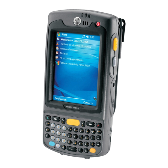
Motorola MC70 Integration Manual
Enterprise digital assistant
Hide thumbs
Also See for MC70:
- User manual (174 pages) ,
- Application brief (4 pages) ,
- Brochure (12 pages)
Table of Contents
Troubleshooting

Related Manuals for Motorola MC70


Summary of Contents for Motorola MC70
- Page 1 MC70 Enterprise Digital Assistant Integrator Guide...
- Page 3 MC70 Integrator Guide 72E-71768-02 Revision A March 2007...
-
Page 4: Patents
Motorola. No right to copy a licensed program in whole or in part is granted, except as permitted under copyright law. The user shall not modify, merge, or incorporate any form or portion of a licensed program with other program material, create a derivative work from a licensed program, or use a licensed program in a network without written permission from Motorola. -
Page 5: Revision History
Revision History Changes to the original manual are listed below: Change Date Description 1/2006 Initial release. 8/2006 Add Revision History page. Chapter 1: Update cold boot procedure. Add clean boot procedure. Chapter 2: Update Ethernet connection procedure. Appendix A: Correct connector pin 1 location. 3/2007 Add MC7095 information... - Page 6 MC70 Integrator Guide...
-
Page 7: Table Of Contents
Table of Contents Patents........................... ii Revision History ......................iii About This Guide Introduction ........................xiii Documentation Set ......................xiii Configurations........................ xiv Software Versions....................xiv Chapter Descriptions ..................... xvii Notational Conventions....................xvii Related Documents and Software ................. xviii Service Information ......................xviii Chapter 1: Getting Started Introduction ........................ - Page 8 viii MC70 Integrator Guide Chapter 2: Accessories Introduction ........................2-1 Cables ........................2-1 Cradles ........................2-1 Miscellaneous ......................2-1 Snap-on Modules ....................2-2 Headset ........................2-2 Multi Media Card (MMC) / Secure Digital (SD) Card ............ 2-2 SD/SDIO Setup ....................... 2-3 Single Slot USB/Serial Cradle ..................
- Page 9 Table of Contents Chapter 3: ActiveSync Introduction ........................3-1 Installing ActiveSync ..................... 3-1 Mobile Computer Setup ....................3-2 Setting Up an ActiveSync Connection on the Host Computer ........3-2 Synchronization with a Windows Mobile 5.0 Device ..........3-3 Chapter 4: Application Deployment for Mobile 5.0 Introduction ........................
- Page 10 MC70 Integrator Guide Configuring a GPRS Data Connection ..............5-3 Establishing a Data Connection ................5-5 Ending a GPRS Data Connection ................5-6 GPRS Settings ......................5-7 Phone ........................5-7 Services ........................5-9 Network ........................5-12 Phone Info ....................... 5-16 Band ........................
- Page 11 Table of Contents Battery Usage ......................7-19 Manage Profiles Application ................... 7-20 Wireless Status Application ..................7-24 Signal Strength Window ..................7-24 Current Profile Window ................... 7-26 IPv4 Status Window ....................7-27 Wireless Log Window ..................... 7-28 Versions Window ....................7-29 Wireless Diagnostics Application ..................
- Page 12 MC70 Integrator Guide Appendix B: Software Configuration Radio Power Status LED ....................B-1 Index...
-
Page 13: About This Guide
About This Guide About This Guide Introduction This Integrator Guide provides information about setting up and configuring MC70 EDAs and accessories. NOTE Screens and windows pictured in this guide are samples and can differ from actual screens. Documentation Set The documentation for the MC70 is divided into guides that provide information for specific user needs. ®... -
Page 14: Configurations
MC70 Integrator Guide Configurations This guide covers the following configurations: Data Operating Configuration Radios Display Memory Keypads Capture System MC7004 WLAN: 802.11b/g 3.5” QVGA 64 MB 1D laser Windows Numeric or Color RAM/ scanner or Mobile 5.0 QWERTY WPAN: Bluetooth 128 MB 2D imager Professional... - Page 15 About This Guide The second line lists the operating system version and the build number. The last part of the build number represents the AKU number. For example, Build 14929.2.2.1 indicates that the device is running AKU version 2.2.1. OEM Version To determine the OEM software version: >...
- Page 16 MC70 Integrator Guide Fusion Software To determine the Fusion software version: icon > > Wireless Strength Wireless Status Versions Phone Software To determine the Phone software version: > > > > tab. Start Phone Menu Options Version Information MC7094 MC7095...
-
Page 17: Chapter Descriptions
About This Guide xvii Chapter Descriptions Topics covered in this guide are as follows: • Chapter 1, Getting Started provides information on EDA configurations and accessories, charging the battery, and resetting. • Chapter 2, Accessories describes the accessories available for the EDA and how to set up power connections and battery charging capabilities, where applicable. -
Page 18: Related Documents And Software
Symbol Global Interactive Center, you may need to return your equipment for servicing and you will be given specific directions. Motorola is not responsible for any damages incurred during shipment if the approved shipping container is not used. Shipping the units improperly can possibly void the warranty. -
Page 19: Chapter 1 Getting Started
Getting Started Chapter 1 Chapter 1 Chapter 1 Getting Started Introduction This chapter provides information about the EDA, accessories, charging the EDA, and resetting the EDA. Unpacking the EDA Carefully remove all protective material from the EDA and save the shipping container for later storage and shipping. -
Page 20: Accessories
1 - 2 MC70 Integrator Guide Accessories Table 1-1 lists the accessories available for the EDA. MC70 Accessories Table 1-1 Accessory Description Snap-on Cables The EDA supports the following cables: • AC line cord (country-specific) and power supply, charges the EDA. •... -
Page 21: Getting Started
Getting Started 1 - 3 Getting Started To start using the EDA for the first time: • Install the main battery and cover assembly. • Charge the EDA. • Power on the EDA. • Configure the EDA. Charge the main battery before or after it is installed. Use one of the spare battery chargers to charge the battery (out of the EDA), or one of the cradles to charge the battery installed in the EDA. -
Page 22: Removing The Main Battery
1 - 4 MC70 Integrator Guide Battery Cover Latch Battery Cover Inserting the Battery Cover Figure 1-2 Close the battery cover latches on either side of the battery cover. Insert the handstrap through the handstrap slot, then tighten and press down to secure. Handstrap Handstrap Slot Inserting the Handstrap... -
Page 23: Charging The Battery
Getting Started 1 - 5 Lift the top of the battery cover and remove. Removing the Battery Cover Figure 1-5 Press the battery release latch on the bottom of the battery to unlock, and lift the battery out of the well. Charging the Battery Charging the Main Battery and Memory Backup Battery Before using the EDA for the first time, charge the main battery until the amber Charge Status LED remains lit... -
Page 24: Charging Spare Batteries
1 - 6 MC70 Integrator Guide The standard capacity battery (1900 mAh) fully charges in less than four hours. The extended capacity battery (3800 mAh) fully charges in less than eight hours. LED Charge Indicators Table 1-2 Charging Status LED Indication EDA is not charging;... -
Page 25: Powering On The Eda
Getting Started 1 - 7 Powering On the EDA Press the Power button to turn on the EDA. If the EDA does not power on, reset it. See Resetting the EDA on page 1-7. When turning the EDA on for the first time, the Symbol splash screen displays for about a minute as the EDA initializes its flash file system, then the calibration window appears. -
Page 26: Waking The Eda
1 - 8 MC70 Integrator Guide A clean boot resets the to the factory default settings. All data is the folder is retained. You Application must download the Clean Boot Package file from the Support Central and install on the To perform a clean boot: Download the Clean Boot Package from the Support Central. -
Page 27: Locking The Eda
Getting Started 1 - 9 Locking the EDA Use the Device Lock feature to prevent use of the device. Note that when locked, the EDA does not respond to screen or keypad input. To lock the device, tap the icon. The icon changes to locked. Device unlocked Device Locked/Unlocked Icons Figure 1-6... - Page 28 1 - 10 MC70 Integrator Guide • Any additional services to which you have subscribed. NOTE For more information about SIM cards, refer to the mobile phone service provider's documentation. To install the SIM card: Press the red button to suspend the EDA. Power Remove the battery.
-
Page 29: Removing The Screen Protector
Getting Started 1 - 11 Removing the Screen Protector A screen protector is applied to the EDA. Symbol recommends using this to minimize wear and tear. Screen protectors enhance the usability and durability of touch screen displays. To remove the screen protector, lift the corner using a thin plastic card, such as a credit card, then carefully lift it off the display. - Page 30 1 - 12 MC70 Integrator Guide...
-
Page 31: Chapter 2: Accessories
Accessories Chapter 2 Chapter 2 Chapter 2 Accessories Introduction MC70 accessories provide a variety of product support capabilities. Accessories include cables, cradles, four-slot spare battery charger, headset, Multimedia Card (MMC), Secure Device (SD) card, Magnetic Stripe Reader (MSR), and trigger handle. Cables Snap one of the following cables on to the EDA to connect an external device. -
Page 32: Snap-On Modules
2 - 2 MC70 Integrator Guide Snap-on Modules • MSR snaps on to the EDA and adds magstripe read capabilities. • TRG7000 Trigger Handle adds a gun-style handle with a scanning trigger to the EDA. Headset Use the headset to communicate via Voice-over-IP (VoIP) or for audio playback. To connect the headset, remove the plug from the headset jack at the top of the EDA and insert the headset connector. -
Page 33: Sd/Sdio Setup
Accessories 2 - 3 Card Cover Removal Figure 2-2 Insert the card with the card contacts facing down and the cut corner on the right, until you feel a click. Replace the housing cover and secure with the screws. To remove an MMC/SD card: Power off the EDA. -
Page 34: Single Slot Usb/Serial Cradle
2 - 4 MC70 Integrator Guide radio button if an SD or MMC card is installed in the SD slot. SDMMC Mode A dialog box displays indicating that the EDA must be reset for the change to take effect. Tap Perform a warm boot. -
Page 35: Charging The Eda Battery
Accessories 2 - 5 Charging the EDA Battery Connect the cradle to power. Insert the EDA into the EDA slot to begin charging. Charge Status LED EDA Battery Charging Figure 2-5 Charging the Spare Battery Spare Battery Spare Battery Charging LED Spare Battery Charging Figure 2-6 Battery Charging Indicators... -
Page 36: Four Slot Ethernet Cradle
2 - 6 MC70 Integrator Guide The standard battery fully charges in approximately four hours and the extended capacity battery fully charges in approximately eight hours. Charging Temperature Charge batteries in temperatures from 0 C to 40 C (32°F to 104°F). Note that at temperatures above 35 charging is intelligently controlled by the EDA and the charging accessory in order to ensure safe operation and optimize long-term battery life. -
Page 37: Daisychaining Cradles
Accessories 2 - 7 Power Port Ethernet Port Ethernet Switch, Router, or Hub Connection Four Slot Ethernet Cradle Connection Figure 2-7 Daisychaining Cradles Daisychain up to four Ethernet cradles to connect several cradles to an Ethernet network. Use either a straight or crossover cable. -
Page 38: Ethernet Cradle Drivers
2 - 8 MC70 Integrator Guide Bandwidth Considerations when Daisychaining Each cradle added to the daisychain impacts the bandwidth provided to the inserted EDAs, particularly when the EDAs attempt to send and receive at data rates that exceed the bandwidth provided to the chain (typically 100 Mbps). - Page 39 Accessories 2 - 9 IP Address Tab Figure 2-10 In the window, select the appropriate radio button: IP address • Use server-assigned IP address • . Enter the IP address, Subnet mask, and Default gateway, as needed. Use specific IP address Tap the tab.
-
Page 40: Charging And Communication
2 - 10 MC70 Integrator Guide Tap ok to exit. Charging and Communication Insert the EDA into a slot to begin charging. Speed LED Link LED EDA Battery Charging Figure 2-13 LED Charging Indicators Charge LED The EDA’s charge LED shows the status of the battery charging in the EDA. See Table 1-2 on page 1-6 charging status indications. -
Page 41: Wall Mount Bracket
Accessories2 - 11 To accomplish this, for small periods of time, the EDA or accessory alternately enables and disables battery charging to keep the battery at acceptable temperatures. The EDA or accessory indicates when charging is disabled due to abnormal temperatures via its LED. See Table 1-2 on page 1-6. - Page 42 2 - 12 MC70 Integrator Guide Four Slot Cradle Bottom Mounting Screw (2) Cradle Mounting Screws Figure 2-15 Align the Wall Mount Bracket mounting tabs with the mounting slots in the back of the four slot cradle. Slip the two mounting tabs into mounting slots. Swing the four slot cradle down onto the mounting bracket and align the mounting screws so that they fit into the screw slots.
-
Page 43: Vcd7000 Vehicle Cradle
Accessories2 - 13 VCD7000 Vehicle Cradle This section describes how to use a VCD7000 vehicle cradle with the EDA. For cradle installation and communication setup procedures refer to the MC70 Integrator Guide. Once installed in a vehicle, the cradle: • holds the EDA securely in place •... -
Page 44: Mounting The Cradle
2 - 14 MC70 Integrator Guide Connector Pin-Outs Power Input Cable Table 2-4 Signal Chassis ground (Bare Wire) Chassis ground (Bare Wire) Connector on Power Cable V+ (Red Wire) V+ (Red Wire) Serial Cable Table 2-5 Signal Signal Connector on Serial Cable 5V_OUT CAUTION ROAD SAFETY - Do not use the EDA while driving. -
Page 45: Power Connection
Accessories2 - 15 1.2” 1.5” Vehicle Cradle Mounting Template Figure 2-18 Position the cradle on the mounting surface. Fasten it using four #8 washers and four #8-32 self-locking nuts. CAUTION Do not install a VCD7000 Vehicle Cradle on or near an air bag cover plate or within an aerobic zone. Also, do not install it in a location that affects vehicle safety or driveability. - Page 46 2 - 16 MC70 Integrator Guide Route the power input cable from the cradle’s power port to the connection point for the vehicle’s power source. CAUTION The means of routing and securing the power input cable from the cradle through to the vehicle power source is extremely important.
-
Page 47: Serial Device Connection
Accessories2 - 17 To see if the cradle has power, insert the EDA. The Charging LED on the EDA blinks slowly to indicate charging and turns solid amber when the battery is completely charged. See Table 1-2 on page 1-6 for other indications. -
Page 48: Charging The Spare Battery
2 - 18 MC70 Integrator Guide Release Lever EDA Battery Charging Figure 2-21 CAUTION Ensure the EDA is fully inserted in the cradle. Lack of proper insertion may result in property damage or personal injury. Symbol Technologies, Inc. is not responsible for any loss resulting from the use of the products while driving. -
Page 49: Battery Charging Indicators
Accessories2 - 19 Battery Release Lever Extended Capacity Battery Shown Inserting the Spare Battery Figure 2-23 Insert the spare battery in the spare battery charging slot in the cradle with the charging contacts facing up and to the rear of the cradle. Release the battery release lever. - Page 50 2 - 20 MC70 Integrator Guide Vehicle Cradle Spare Battery LED Charging Indicators Table 2-6 Spare Battery LED Indication (on cradle) Slow Blinking Amber Spare battery is charging. Solid Amber Spare battery is fully charged. Fast Blinking Amber Charging error. Not charging.
-
Page 51: Four Slot Spare Battery Charger
Accessories2 - 21 Four Slot Spare Battery Charger This section describes how to use the Four Slot Spare Battery Charger to charge up to four EDA spare batteries. NOTE Use only a Symbol-approved power supply output rated 12 Vdc and minimum 3.33A. The power supply is certified to EN60950 with SELV outputs. -
Page 52: Spare Battery Charging
2 - 22 MC70 Integrator Guide Spare Battery Charging Connect the charger to a power source. Insert the spare battery into a spare battery charging well and gently press down on the battery to ensure proper contact. Spare Battery Spare Battery Charging LEDs (4) Four Slot Spare Battery Charger Figure 2-26... -
Page 53: Magnetic Stripe Reader (Msr)
Accessories2 - 23 Spare Battery LED Charging Indicators Table 2-7 Indication No spare battery in slot; spare battery not placed correctly; cradle is not powered. Fast Blinking Amber Error in charging; check placement of spare battery. Slow Blinking Amber Spare battery is charging. Solid Amber Charging complete. -
Page 54: Using The Msr
2 - 24 MC70 Integrator Guide Using the MSR The MSR3000 sample application illustrates how an application handles MSR inputs (refer to Symbol Applications User’s Guide). To use the MSR: Attach the MSR to the EDA. Power on the EDA. >... -
Page 55: Inserting The Eda Into The Trigger Handle
Accessories2 - 25 Back Housing Bracket Removing Back Housing Bracket Figure 2-29 Install the rubber headset jack dust cover onto the trigger handle cleat. Align the trigger handle cleat onto the EDA. Secure the trigger handle cleat to the EDA using the four screws saved during step 2. Installing the Cleat Figure 2-30 Feed the handstrap through the handstrap slot and secure. -
Page 56: Removing The Eda
2 - 26 MC70 Integrator Guide Removing the EDA To remove the EDA, press the release down and pull the EDA forward. Release Removing the EDA Figure 2-32 Using a Cradle With the Trigger Handle you can charge the EDA and communicate with a host computer using either the serial charging cable or a cradle, or connect to a peripheral such as a printer. -
Page 57: Cables
Accessories2 - 27 To charge the EDA’s battery while the EDA is in the Trigger Handle, insert the EDA into either the Single Slot USB/Serial cradle or the Four Slot Ethernet cradle. Inserting the EDA Into the Cradle for Charging Figure 2-34 Cables This section describes how to set up and use the cables. -
Page 58: Setup
2 - 28 MC70 Integrator Guide Cables (MC70 Connector) Figure 2-35 The communication/charge cables: • Provide the EDA with operating and charging power when used with the Symbol approved power supply. • Synchronize information between the EDA and a host computer. With customized or third party software, it can also synchronize the EDA with corporate databases. -
Page 59: Battery Charging
Accessories2 - 29 Battery Charging The communication/charge cables can charge the EDA battery and supply operating power. To charge the EDA battery: Connect the communication/charge cable power input connector to the Symbol approved power source. Slide the bottom of the EDA into the connector end of the communication/charge cable and gently press in until it latches into the EDA. - Page 60 2 - 30 MC70 Integrator Guide...
-
Page 61: Chapter 3: Activesync
ActiveSync Chapter 3 Chapter 3 Chapter 3 ActiveSync Introduction To communicate with various host devices, install Microsoft ActiveSync (version 4.1 or higher) on the host computer. Use ActiveSync to synchronize information on the mobile computer with information on the host computer. -
Page 62: Mobile Computer Setup
3 - 2 MC70 Integrator Guide Mobile Computer Setup NOTE Microsoft recommends installing ActiveSync on the host computer before connecting the mobile computer. The mobile computer can be set up to communicate either with a serial connection or a USB connection. Chapter 2, Accessories provides the accessory setup and cable connection information for use with the mobile computer. -
Page 63: Synchronization With A Windows Mobile 5.0 Device
ActiveSync 3 - 3 ActiveSync Window Figure 3-2 NOTE Assign each mobile computer a unique device name. Do not try to synchronize more than one mobile computer to the same name. In the window, select > . The window appears. ActiveSync File Connection Settings... - Page 64 3 - 4 MC70 Integrator Guide Synchronization Setup Wizard Window Figure 3-4 Click Next Synchronization Directly With a Server Window Figure 3-5 Select the check box to synchronize with a server running Microsoft Exchange if applicable. Click Next...
- Page 65 ActiveSync 3 - 5 Synchronization Option Window Figure 3-6 Select the appropriate settings and click Next Wizard Complete Window Figure 3-7 Click Finish...
- Page 66 3 - 6 MC70 Integrator Guide ActiveSync Connected Window Figure 3-8 During the first synchronization, information stored on the mobile computer is copied to the host computer. When the copy is complete and all data is synchronized, the mobile computer can be disconnect from the host computer.
-
Page 67: Chapter 4: Application Deployment For Mobile
Application Deployment for Mobile 5.0 Chapter 4 Chapter 4 Chapter 4 Application Deployment for Mobile 5.0 Introduction This chapter describes new features in Windows Mobile 5.0 including new security features, how to package applications, and procedures for deploying applications onto the EDA. Security The MC70 EDAs implement a set of security policies that determine whether an application is allowed to run and, if allowed, with what level of trust. - Page 68 4 - 2 MC70 Integrator Guide To support the broadest number of deployments, third-party software developers should perform the following when releasing software for a Windows Mobile 5.0 devices: • Sign all their EXEs & DLLs with their private key •...
-
Page 69: Device Management Security
Application Deployment for Mobile 5.0 4 - 3 Installing Certificates Use XML provisioning to query and delete certificates from certificate stores. To add a new certificate the Privileged Execution Trust Certificate Store, use the following sample provisioning document: <wap-provisioningdoc> <characteristic type=”CertificateStore”> <characteristic type=”Privileged Execution Trust Authorities”>... -
Page 70: Remote Api Security
4 - 4 MC70 Integrator Guide Remote API Security The Remote API (RAPI) enables applications that run on a desktop to perform actions on a remote device. RAPI provides the ability to manipulate the file system on the remote device, including the creation and deletion of files and directories. -
Page 71: Installation Using Storage Card
Application Deployment for Mobile 5.0 4 - 5 Installation Using Storage Card To install an application package: • Copy the package CAB file to a storage card using an appropriate storage card reader. • Install the storage card into the EDA. See Multi Media Card (MMC) / Secure Digital (SD) Card on page for more information. -
Page 72: Creating A Splash Screen
4 - 6 MC70 Integrator Guide When it finds the appropriate file, it loads the package onto the EDA. A progress bar displays until the update completes. The EDA re-boots. The calibration screen appears. NOTE When initiating an update via a boot sequence, the update loader looks for updates first on the root of an installed SD card and then in the \temp folder on the EDA’s persistent storage volume. -
Page 73: Creating An Xml Provisioning File
Application Deployment for Mobile 5.0 4 - 7 certain privileges (roles). Some registry keys require you to simply be an Authenticated User, while other registry keys require you to be a Manager. Refer to the Microsoft Windows Mobile 5.0 Help file, Metabase Settings for Registry Configuration Service Provider section, for the default role settings in Windows Mobile 5.0. - Page 74 4 - 8 MC70 Integrator Guide The following example uses XML provisioning to perform the same task: SampleReg.xml <wap-provisioningdoc> <characteristic type="Registry"> <characteristic type="HKLM\Hardware\DeviceMap\Backlight"> <parm name="BacklightIntensity" value="54" datatype="integer" /> </characteristic> </characteristic> </wap-provisioningdoc> CopyFiles CopyFiles copies files from one folder to another on a clean boot. During a clean boot CopyFiles looks for files with a .CPY extension in the root of the Application FFS partition.
-
Page 75: Storage
Application Deployment for Mobile 5.0 4 - 9 Storage Mobile 5.0 contains three types of file storage: • Random Access Memory (RAM) • Persistent Storage • Application folder. Random Access Memory Executing programs use RAM to store data. Data stored in RAM is lost upon a warm boot. RAM also included a volatile file storage area called Cache Disk. -
Page 76: Application Folder
4 - 10 MC70 Integrator Guide Application Folder The Application folder is a super-persistent storage that is persistent even after a clean boot. Accessing data in the Application folder is slower than accessing persistent storage. The Application folder is used for deployment and device-unique data. - Page 77 Application Deployment for Mobile 5.0 4 - 11 Main SCM Window Figure 4-1 Menu Functions Use the main menu to access the program functionality described in Table 4-1. SCM Menu Functions Table 4-1 Menu Item Description File Menu Open Config File Open a saved configuration file (.SCD).
-
Page 78: File Deployment
4 - 12 MC70 Integrator Guide Parameter State Indicators The first column of the data table displays parameter state indicators. The state indicators display one of the states in Table 4-2 for a particular parameter: Parameter Status Indicators Table 4-2 Icon Indicator Description... -
Page 79: Rapid Deployment Client
Application Deployment for Mobile 5.0 4 - 13 Rapid Deployment Client The Rapid Deployment (RD) Client facilitates software downloads to a EDA from a Mobility Services Platform (MSP) Console’s FTP server. The MSP Console is a web-based interface to the wireless infrastructure monitoring and management tools provided by the MSP Lite or MSP Enterprise server. -
Page 80: Scanning Rd Bar Codes
4 - 14 MC70 Integrator Guide Rapid Deployment Window Table 4-4 Text Box/Button Description Please scan all of the bar Displays the status of a scanned bar code. codes... Waiting - indicates the EDA is ready to scan a bar code. OK - indicates the EDA successfully scanned a bar code. - Page 81 Application Deployment for Mobile 5.0 4 - 15 Ready to Scan Ready to Scan No Bar Codes Left to Scan Bar Codes Left to Scan are Listed Rapid Deployment Window Figure 4-4 Scan the appropriate bar code(s) to complete the configuration and/or download. A PDF417 bar code (2-D bar code) can contain all download data in a single bar code.
-
Page 82: Airbeam Smart
4 - 16 MC70 Integrator Guide • The designated package(s) are downloaded from the FTP server. AirBEAM Smart The AirBEAM Smart product allows specially designed software packages to be transferred between a host server and Symbol wireless handheld devices. Before transfer, AirBEAM Smart checks and compares package versions, so that only updated packages are loaded. -
Page 83: Airbeam Smart Client
Application Deployment for Mobile 5.0 4 - 17 AirBEAM Smart Client The AirBEAM Smart Client resides on the handheld EDA. It is configured with the server access information, the names of the packages to be downloaded and other controlling parameters. When the AirBEAM Smart Client is launched, the device connects to the specified FTP server and checks the packages it is configured to look for. - Page 84 4 - 18 MC70 Integrator Guide Packages(1) Tab Use this tab to specify the package name of the first four of eight packages to load during the AirBEAM synchronization process. The specified package name must correspond to a package available on the specified package server.
- Page 85 Application Deployment for Mobile 5.0 4 - 19 Packages(2) Tab Use this tab to specify the package name of the last four of eight packages to load during the AirBEAM synchronization process. The specified package name must correspond to a package available on the specified package server.
- Page 86 4 - 20 MC70 Integrator Guide Server Tab Use this tab to specify the configurations of the server to which the client connects during the package synchronization process. Server Tab Figure 4-9 Server Tab Table 4-7 Field Description IP Address The IP Address of the server.
- Page 87 Application Deployment for Mobile 5.0 4 - 21 Misc(1) Tab Use this tab to configure various miscellaneous features. Misc(1) Tab Figure 4-10 Misc(1) Tab Table 4-8 Field Description Auto-load Use this drop-down list to specify how to invoke the AirBEAM Smart Client when the client device is rebooted.
- Page 88 4 - 22 MC70 Integrator Guide Misc(2) Tab Use this tab to configure various miscellaneous features. Misc(2) Tab Figure 4-11 Misc(2) Tab Table 4-9 Field Description Auto-retry Use this field to specify whether the AirBEAM Smart Client automatically retries if synchronization fails.
-
Page 89: Synchronizing With The Server
Application Deployment for Mobile 5.0 4 - 23 Misc(3) Tab Use this tab to configure various miscellaneous features. Misc(3) Tab Figure 4-12 Misc(3) Tab Table 4-10 Field Description Use DHCP server This check box control specifies whether the AirBEAM Smart Client uses the DHCP response option 66 to specify the IP address of the FTP/TFTP server. -
Page 90: Airbeam Staging
4 - 24 MC70 Integrator Guide AirBEAM Synchronize Window Figure 4-13 • The Status List displays messages that indicate the synchronization progress. • Tap to return to the Main Menu. This button remains inactive until synchronization completes. • Tap to restart synchronization. This button is active only if there is an error during Retry synchronization. -
Page 91: Chapter 5 Mc7004/94 - Gsm Configuration
MC7004/94 - GSM Configuration Chapter 5 Chapter 5 Chapter 5 MC7004/94 - GSM Configuration Introduction This chapter explains how to verify MC7004/94 service on an Enhanced Data rates for Global Evolution (EDGE) wireless network and establish settings. EDGE is also known as Enhanced General Packet Radio Service (EGPRS). -
Page 92: Mc7004/94 Service Verification
5 - 2 MC70 Integrator Guide Configure settings (page 5-7). Use the phone. MC7004/94 Service Verification MC7004/94 phone and data services require a live SIM card, obtained from a service provider, installed in the EDA phone/EDA. The SIM card has embedded circuitry on one side of its surface which, when inserted into an EDA phone, provides phone service on an EDGE network. -
Page 93: Configuring A Gprs Data Connection
MC7004/94 - GSM Configuration 5 - 3 Phone Settings Window - Network Tab Figure 5-2 Ensure the service provider’s network appears in the Current network: field. If the network does not appear, tap Find Network. If the network still does not appear, verify that the SIM card was installed correctly. - Page 94 5 - 4 MC70 Integrator Guide Under select My ISP Add a new modem connection Connections Window - Make New Connection Figure 5-4 Enter a connection name in the Enter a name for the connection: text box. Select from the drop-down list.
-
Page 95: Establishing A Data Connection
MC7004/94 - GSM Configuration 5 - 5 Connections Window - User Name & Password Figure 5-6 (user name and password are not required). Finish to exit Connections Establishing a Data Connection Install a SIM card in the EDA. Configure a GPRS data connection. See Configuring a GPRS Data Connection on page 5-3. -
Page 96: Ending A Gprs Data Connection
5 - 6 MC70 Integrator Guide Data Connection Figure 5-8 Select Connect Connecting Using IDEN Packet Data Modem Figure 5-9 If the SIM card is protected with a Personal Identification Number (PIN), a dialog box pops up requesting the appropriate PIN to unlock the SIM card. In this case, enter the PIN and tap NOTE Place emergency calls at any time, without entering a PIN or a SIM card When a connection is established, launch to browse the Internet or launch an applicable... -
Page 97: Gprs Settings
MC7004/94 - GSM Configuration 5 - 7 Connectivity Dialog Box Figure 5-10 Disconnect NOTE Tapping Disconnect during an active data transfer (e.g., downloading a web page) automatically reconnects the GPRS connection. You cannot disconnect the GPRS connection until the data transfer is complete GPRS Settings Use the... - Page 98 5 - 8 MC70 Integrator Guide Sounds automatically displays on the tab when a live SIM card is installed. Phone Number Phone Select a ring type from the drop-down list. The ring type changes the way the EDA rings when Ring type: you receive an incoming call.
-
Page 99: Services
MC7004/94 - GSM Configuration 5 - 9 Changing a PIN From the (Figure 5-11), tap Phone Change PIN Use the touch keypad to enter the current PIN. Enter Use the touch keypad to enter a new four to eight digit PIN. Enter Reenter the new PIN for confirmation and tap Enter... - Page 100 5 - 10 MC70 Integrator Guide Change services settings as follows. Call Barring (Call Blocking) Use call barring to block certain types of incoming and/or outgoing calls. Select the type of incoming and/or outgoing calls to block. Call Barring/Call Blocking Figure 5-14 Caller ID Enable caller ID to reveal the identity of the person making an outgoing call.
- Page 101 MC7004/94 - GSM Configuration 5 - 11 • To forward incoming calls to a different phone number based on a specific situation, select one or more of the check boxes under Forward phone calls only if: • enter the phone number to receive forwarded calls only when the phone cannot be No answer: answered.
-
Page 102: Network
5 - 12 MC70 Integrator Guide Voice Mail and Text Messages Figure 5-18 Fixed Dialing Use Fixed Dialing to restrict the phone to dial only the phone number(s) or area code(s) specified in a Fixed Dialing list. Select and tap Fixed Dialing Get Settings Fixed Dialing Window... - Page 103 MC7004/94 - GSM Configuration 5 - 13 The network the EDA currently uses appears in the field at the top of the window. Current network: Changing Networks Manually > > tab > icon > Start Settings Personal Phone Network > >...
- Page 104 5 - 14 MC70 Integrator Guide MC70 Phone Window - Network Tab Figure 5-22 Find Network Choose Network Figure 5-23 From the window, select the network to use. Choose Network...
- Page 105 MC7004/94 - GSM Configuration 5 - 15 Setting Preferred Networks Set networks in a preferred order of access. Setting preferred networks allows the EDA to access a second preferred network if the first is unavailable. > > tab > icon > Start Settings Personal...
-
Page 106: Phone Info
5 - 16 MC70 Integrator Guide Phone Info Use the Phone Info tab to view hardware and software information about the phone. > > tab > icon > Start Settings Personal Phone Phone Info > > > > tab. Start Phone Menu Options... - Page 107 MC7004/94 - GSM Configuration 5 - 17 Select the 8 check box to enable the radio to hand over in the band of 850MHz (in addition 50 MHz Enabled to PCS1900MHz/DCS1800MHz). Disable only for some special networks outside of the United States and Europe. Handover Enhancement to exit settings.
- Page 108 5 - 18 MC70 Integrator Guide...
-
Page 109: Chapter 6 Mc7095 - Cdma Configuration
MC7095 - CDMA Configuration Chapter 6 Chapter 6 Chapter 6 MC7095 - CDMA Configuration Introduction This chapter explains how to activate an MC7095 EDA on a CDMA wireless network and establish settings. CDMA is a form of wireless multiplexing in which data (e.g., Short Message Service) can be sent over multiple frequencies simultaneously, optimizing the use of available bandwidth. -
Page 110: Mc7095 Cdma Phone Activation
6 - 2 MC70 Integrator Guide MC7095 CDMA Phone Activation ® ® CDMA phone service is available from a number of service providers including Sprint and Verizon . In addition to service activation for each provider, various settings may be required for the MC7095 to operate as a phone. - Page 111 MC7095 - CDMA Configuration 6 - 3 Sprint Activation Wizard - MDN and MSID Figure 6-3 Enter the MDN and MSID. The MDN and MSID are the area code and phone number received from the service provider. Tap Next >. Sprint Activation Wizard - Confirmation Figure 6-4 Verify that the MDN and MSIN numbers entered are correct, tap...
-
Page 112: Sprint Activation Test
6 - 4 MC70 Integrator Guide to complete activation. The phone can be used in approximately four hours. Finish Sprint Activation Test Approximately four hours after activation is completed, test the service. > Start Phone Sprint Phone Window Figure 6-6 Ensure the Sprint name displays on the window. - Page 113 MC7095 - CDMA Configuration 6 - 5 Verizon Activation Wizard Figure 6-7 Tap Start to connect to the Verizon Wireless Network to automate activation. Automated activation provides all required codes and identification numbers over the network. No additional activation setup is required.
-
Page 114: Verizon Activation Test
6 - 6 MC70 Integrator Guide to complete activation. The phone can be used in approximately four hours, depending on the Finish network provider load. Verizon Activation Test Approximately four hours after activation is completed, test the service. > Start Phone Verizon Phone Window Figure 6-10... -
Page 115: Establishing A Cdma Data Connection
MC7095 - CDMA Configuration 6 - 7 Establishing a CDMA Data Connection A CDMA data connection allows Internet access across a wireless network. Data connection is pre-packaged with service accounts. To verify active data service: to display the dialog. Connectivity Data Connection Figure 6-11 Tap #777 for a data connection using the Cellular Line. -
Page 116: Cdma Settings
6 - 8 MC70 Integrator Guide CDMA Settings Use the window to customize CDMA phone settings, such as the ring type and ring tone for Phone Settings incoming calls and other options depending on the type of service. Phone Use the tab to customize ring type, ring tone and keypad tone when entering phone numbers. -
Page 117: Location Settings
MC7095 - CDMA Configuration 6 - 9 to exit settings. NOTE Turning off sounds saves power and prolongs battery life. Location Settings Use the tab to allow the network to detect the position of the MC7095’s radio. Location > > tab >... - Page 118 6 - 10 MC70 Integrator Guide Phone Window - Sprint Data Tab Figure 6-14 to reset PCS Vision connection settings. Repair Connectiod Reset Connection Settings Dialog Figure 6-15 Reset Connection Completed Dialog Figure 6-16 to manually start IP-based Over-The-Air (IOTA) provisioning. Provision...
- Page 119 MC7095 - CDMA Configuration 6 - 11 IOTA is used to provision various data elements such as Wireless Application Protocol (WAP) configuration parameters and roaming lists to the MC7095 over-the-air. It is also used to provision other elements such as applications and firmware. to exit settings.
-
Page 120: System Settings
6 - 12 MC70 Integrator Guide Phone Window - Data Tab Figure 6-18 to reset connection settings for the 3G connection. Reset Connection to exit settings. System Settings Use the tab to select roaming options. System Settings > > tab > icon >... - Page 121 MC7095 - CDMA Configuration 6 - 13 • Select the radio button to allow the phone to automatically seek a roaming network where the Automatic Sprint Nationwide PCS Network is not available. Automatic roaming is available where Sprint implemented roaming with other wireless carriers. •...
-
Page 122: Version Information
6 - 14 MC70 Integrator Guide Additional Service Provider System Phone Window - System Settings Tab - Additional Figure 6-21 System Select allows the user to change the system roaming preference of the radio in order to control the type of network the radio can lock onto for service. •... -
Page 123: Services
MC7095 - CDMA Configuration 6 - 15 MC7095 Phone Window - Phone Info Tab Figure 6-22 to exit settings. Services Depending on the type of subscribed phone services, the following services may be available: call barring, caller ID, call forwarding, call waiting, voice mail and Short Message Service (SMS). Call Barring (Call Blocking) Call barring blocks certain types of incoming and/or outgoing calls. - Page 124 6 - 16 MC70 Integrator Guide Enter *720 on the phone keypad. Talk A beep sounds indicating deactivation. Call Waiting Call waiting notifies the user of an incoming call when the phone is in a phone session. This service is setup when an account is opened with the service provider.
-
Page 125: Chapter 7 Wireless Applications
Wireless Applications Chapter 7 Chapter 7 Chapter 7 Wireless Applications Introduction Wireless Local Area Networks (LANs) allow mobile computers to communicate wirelessly and send captured data to a host device in real time. Before using the EDA on a WLAN, the facility must be set up with the required hardware to run the wireless LAN and the EDA must be configured. -
Page 126: Signal Strength Icon
7 - 2 MC70 Integrator Guide Signal Strength Icon icon in the task tray indicates the EDA’s wireless signal strength as follows: Signal Strength Wireless Applications Icons, Signal Strength Descriptions Table 7-1 Icon Status Action Excellent signal strength Wireless LAN network is ready to use. Very good signal strength Wireless LAN network is ready to use. -
Page 127: Find Wlans Application
Wireless Applications 7 - 3 Enable Radio Figure 7-3 Find WLANs Application Use the application to discover available networks in the vicinity of the user and EDA. To open the Find WLANs application, tap the icon > . The window displays. Find WLANs Signal Strength Find WLANs... -
Page 128: Profile Editor Wizard
7 - 4 MC70 Integrator Guide Signal Strength Icon Table 7-2 Icon Description Excellent signal Very good signal Good signal Fair signal Poor signal Out of range or no signal Encryption Icon Table 7-3 Icon Description No encryption. WLAN is an infrastructure network. WLAN is an Ad-Hoc network. -
Page 129: Operating Mode
Wireless Applications 7 - 5 Profile ID Fields Table 7-4 Field Description Name The name and (WLAN) identifier of the network connection. Enter a user friendly name for the mobile computer profile used to connect to either an AP or another networked computer. - Page 130 7 - 6 MC70 Integrator Guide Operating Mode Fields Table 7-5 Field Description Operating Mode Select to enable the EDA to transmit and receive data with an AP. Infrastructure Infrastructure is the default mode. Select to enable the EDA to form its own local network where mobile computers Ad Hoc communicate peer-to-peer without APs using a shared ESSID.
-
Page 131: Ad-Hoc
Wireless Applications 7 - 7 Ad-Hoc Use the dialog box to select the required information to control Ad-Hoc mode. This dialog box does not Ad-Hoc appear if you selected mode. To select Ad-Hoc mode: Infrastructure Select a channel number from the drop-down list. -
Page 132: Tunneled Authentication
7 - 8 MC70 Integrator Guide Tunneled Authentication Use the dialog box to select the tunneled authentication options. There are different Tunneled Authentication selections available for PEAP or TTLS authentication. Tunneled Authentication Dialog Box Figure 7-9 To select a tunneled authentication type: Select a tunneled authentication type from the drop-down list. -
Page 133: User Certificate Selection
Wireless Applications 7 - 9 Table 7-8 lists the TTLS tunneled authentication options. TTLS Tunneled Authentication Options Table 7-8 TTLS Tunneled Description Authentication CHAP Challenge Handshake Authentication Protocol (CHAP) is one of the two main authentication protocols used to verify the user name and password for PPP Internet connections. -
Page 134: Server Certificate Selection
7 - 10 MC70 Integrator Guide User Certificate Installation To install a user certificate (EAP TLS only) and a server certificate for EAP TLS and PEAP authentication: . The dialog box appears. Install Certificate Credentials Credentials Dialog Box Figure 7-11 Enter the (password), and information in their respective text boxes. -
Page 135: Credential Cache Options
Wireless Applications 7 - 11 Browse Server Certificates Figure 7-13 Press the key to change the default path or extension (and search a new path). Select a certificate before tapping the button. Install Confirmation Dialog Box Figure 7-14 A confirmation dialog verifies the installation. If the information in this dialog is correct, tap the button, If the information in this dialog is not correct tap the button. - Page 136 7 - 12 MC70 Integrator Guide Prompt for Login at Dialog Box Figure 7-15 If the EDA does not have the credentials, you are prompted to enter a username and password. If the EDA has the credentials (previous entered via a login dialog box), it uses these credentials unless the caching options require the EDA to prompt for new credentials.
-
Page 137: Password
Wireless Applications 7 - 13 Tap the radio button to check credentials at a set time interval. Interval Enter the value in minutes in the box. Tap the radio button to check credentials at a set time. At (hh:mm) . The dialog box appears. -
Page 138: Advanced Identity
7 - 14 MC70 Integrator Guide . The dialog box displays. See Encryption on page 7-14. Next Encryption Advanced Identity Use the dialog box to enter the 802.1X identity to supply to the authenticator. This value can be 63 Advanced ID characters long and is case sensitive. - Page 139 Wireless Applications 7 - 15 Encryption Options Table 7-10 Encryption Description Open Select (the default) when no data packet encryption is needed over the network. Open Selecting this option provides no security for data transmitting over the network. 40-Bit WEP Select to use 40-bit key length WEP encryption.
-
Page 140: Ip Mode
7 - 16 MC70 Integrator Guide Key Entry Page If you select either the wizard proceeds to the key entry dialog box unless the 40-Bit WEP 128-Bit WEP check box was selected in the dialog box (see Figure 7-21 on page 7-14). -
Page 141: Ip Address Entry
Wireless Applications 7 - 17 IP Config Tab (DHCP) Figure 7-24 IP Mode Options Table 7-12 Encryption Description DHCP Select Dynamic Host Configuration Protocol ( ) from the drop-down list to DHCP IP Mode obtain a leased IP address and network configuration information from a remote server. DHCP is the default setting for the EDA profile. -
Page 142: Transmit Power
7 - 18 MC70 Integrator Guide Select the check box, then tap to display the dialog box. Enter the Advanced NEXT Advanced Address Entry Gateway, DNS, and WINS address. Tap without selecting the check box to display the NEXT Advanced dialog box. -
Page 143: Battery Usage
Wireless Applications 7 - 19 Transmit Power Dialog Box (Infrastructure Mode) Table 7-15 Field Description Automatic Select (the default) to use the AP power level. Automatic Power Plus Select to set the EDA transmission power one level higher than the level Power Plus set for the AP. -
Page 144: Manage Profiles Application
7 - 20 MC70 Integrator Guide Battery Usage Dialog Box Figure 7-29 NOTE Power consumption is also related to the transmit power settings. Battery Usage Options Table 7-17 Field Description Continuous Aware Mode ( ) provides the best network performance, but yields the shortest battery life. - Page 145 Wireless Applications 7 - 21 Icons next to each profile identify the profile’s current state. Profile Icons Table 7-18 Icon Description No Icon Profile is not selected, but enabled. Profile is disabled. Profile is cancelled. A cancelled profile is disabled until a connect or login function is performed through the configuration editor.
- Page 146 7 - 22 MC70 Integrator Guide Manage Profiles Figure 7-32 Tap and hold a profile and select from the pop-up menu to set this as the active profile. Once selected, Connect the EDA uses the authentication, encryption, ESSID, IP Config, and power consumption settings configured for that profile.
- Page 147 Wireless Applications 7 - 23 Ordering Profiles Tap and hold a profile from the list and select to order the profile. If the current profile Move Up Move Down association is lost, the EDA attempts to associate with the first profile in the list, then the next, until it achieves a new association.
-
Page 148: Wireless Status Application
7 - 24 MC70 Integrator Guide Wireless Status Application To open the window, tap the icon > . The window Wireless Status Signal Strength Wireless Status Wireless Status displays information about the wireless connection. Wireless Status Window Figure 7-35 window contains the following options. Tap the option to display the option window. Wireless Status •... - Page 149 Wireless Applications 7 - 25 Signal Strength Window Figure 7-36 After viewing the window, tap the back button to return to the window. Signal Strength Wireless Status Signal Strength Status Table 7-19 Field Description Signal Displays the Relative Signal Strength Indicator (RSSI) of the signal transmitted between the AP and EDA.
-
Page 150: Current Profile Window
7 - 26 MC70 Integrator Guide Signal Strength Status (Continued) Table 7-19 Field Description Association Count Displays the number of APs the EDA connects to while roaming. AP MAC Address Displays the MAC address of the AP to which the EDA is connected. Transmit Rate Displays the current rate of the data transmission. -
Page 151: Ipv4 Status Window
Wireless Applications 7 - 27 IPv4 Status Window window displays the current IP address, subnet, and other IP related information assigned to IPv4 Status the EDA. It also allows renewing the address if the profile is using DHCP to obtain the IP information. Tap to initiate a full DHCP discover. -
Page 152: Wireless Log Window
7 - 28 MC70 Integrator Guide IPv4 Status Fields (Continued) Table 7-21 Field Description Lease Displays the date that the IP address expires and a new IP address is requested. Expires Displays the IP address of the DNS server. WINS WINS is a Microsoft Net BIOS name server. -
Page 153: Versions Window
Wireless Applications 7 - 29 Versions Window window displays software, firmware, and hardware version numbers. This window only updates Versions when it is displayed. There is no need to update constantly. The content of the window is determined at runtime, along with the actual hardware and software to display in the list. Executable paths of the software components on the list are defined in registry, so that the application can retrieve version information from the executable. -
Page 154: Wireless Diagnostics Application
7 - 30 MC70 Integrator Guide Wireless Diagnostics Application application window provides links to perform ICMP Ping, Trace Routing, and Known Wireless Diagnostics APs. To open the window, tap the icon > Wireless Diagnostics Signal Strength Wireless Diagnostics Wireless Diagnostics Window Figure 7-41 window contains the following options. -
Page 155: Trace Route Window
Wireless Applications 7 - 31 ICMP Ping Window Figure 7-42 To perform an ICMP ping: In the field, enter an IP address or select an IP address from the drop-down list. From the drop-down list, select a size value. Size . -
Page 156: Known Aps Window
7 - 32 MC70 Integrator Guide Known APs Window window displays the APs in range using the same ESSID as the EDA. This window is only Known APs available in mode. To open the window, tap in the Infrastructure Known APs Known APs Wireless Diagnostics window. -
Page 157: Options
Wireless Applications 7 - 33 Options Use the wireless dialog box to select one of the following operation options from the drop-down list: Option • Operating Mode Filtering • Regulatory • Band Selection • System Options • Change Password • Export. -
Page 158: Band Selection
7 - 34 MC70 Integrator Guide Regulatory Options Dialog Box Figure 7-46 Regulatory Options Table 7-24 Field Description Settings Select the country from the drop-down list. To connect to a profile, the profile country must match this setting, or the AP country setting if you selected the Enable 802.11d check box. -
Page 159: Change Password
Wireless Applications 7 - 35 System Options Dialog Box Figure 7-48 System Options Table 7-26 Field Description Profile Roaming Configures the EDA to roam to the next available WLAN profile when it moves out of range of the current WLAN profile. Enable IP Mgmt Enables the Wireless Companion Services to handle IP address management. -
Page 160: Export
7 - 36 MC70 Integrator Guide Export to export all profiles to a registry file, and to export the options to a registry file. Export Options - Export Dialog Box Figure 7-50 To export options: . The dialog box displays. Export Options Save As Export Options Save As Dialog Box... -
Page 161: Cold Boot Persistence
Wireless Applications 7 - 37 Enter a filename in the field. The default filename is WCS_PROFILES.REG. Name: In the drop-down list, select the desired folder. Folder: Save Selecting saves the current profile. This information is used to determine which profile to Export All Profiles connect with after a warm boot or cold boot. -
Page 162: User Already Logged In
7 - 38 MC70 Integrator Guide User Already Logged In If already logged into the EDA, the user can launch the login dialog box for the following reasons: • Connect to and re-enable a cancelled profile. To do this: • Launch the Log On/Off dialog. •... - Page 163 Wireless Applications 7 - 39 Tapping sends the credentials though WCS API. If there are no credentials entered, a dialog box displays informing the user which field was not entered. button only displays when a user is already logged on. When the button is tapped, the user Log Off Log Off...
- Page 164 7 - 40 MC70 Integrator Guide...
-
Page 165: Chapter 8 Maintenance And Troubleshooting
Maintenance and Troubleshooting Chapter 8 Chapter 8 Chapter 8 Maintenance and Troubleshooting Introduction This chapter includes instructions on cleaning and storing the EDA, and provides troubleshooting solutions for potential problems during EDA operation. Maintaining the EDA For trouble-free service, observe the following tips when using the EDA: •... -
Page 166: Troubleshooting
8 - 2 MC70 Integrator Guide Troubleshooting Troubleshooting the EDA Table 8-1 Problem Cause Solution EDA does not turn Lithium-ion battery Charge or replace the lithium-ion battery in the EDA. not charged. Lithium-ion battery Ensure battery is installed properly. See Installing and not installed Removing the Main Battery on page... - Page 167 Maintenance and Troubleshooting 8 - 3 Troubleshooting the EDA (Continued) Table 8-1 Problem Cause Solution EDA shuts off. EDA is inactive. The EDA turns off after a period of inactivity. If the EDA is running on battery power, set this period from 1 to 5 minutes, in one-minute intervals.
-
Page 168: Bluetooth Connection
8 - 4 MC70 Integrator Guide Troubleshooting the EDA (Continued) Table 8-1 Problem Cause Solution The EDA does not Scanning Load a scanning application on the EDA. See the system accept scan input. application is not administrator. loaded. Unreadable bar Ensure the symbol is not defaced. - Page 169 Maintenance and Troubleshooting 8 - 5 Troubleshooting Bluetooth Connection (Continued) Table 8-2 Problem Cause Solution Can’t make my You attempted to bond Reset the phone by removing its battery. Ericsson R520 with the phone, and phone discoverable. when the phone presented a “pairing query,”...
-
Page 170: Single Slot Usb/Serial Cradle
8 - 6 MC70 Integrator Guide Single Slot USB/Serial Cradle Troubleshooting the Single Slot USB/Serial Cradle Table 8-3 Symptom Possible Cause Action LEDs do not light Cradle is not receiving Ensure the power cable is connected securely to both the when EDA or spare power. -
Page 171: Four Slot Ethernet Cradle
Maintenance and Troubleshooting 8 - 7 Four Slot Ethernet Cradle Troubleshooting the Four Slot Ethernet Cradle Table 8-4 Symptom Cause Solution Battery is not EDA removed from the Replace the EDA in the cradle. The standard capacity charging. cradle too soon. battery (1900 mAh) fully charges in less than four hours. -
Page 172: Vehicle Cradle
8 - 8 MC70 Integrator Guide Vehicle Cradle Troubleshooting the Vehicle Cradle Table 8-5 Symptom Possible Cause Action EDA battery Cradle is not receiving Ensure the power input cable is securely connected to the charging LED does power. cradle’s power port. not light up. -
Page 173: Four Slot Spare Battery Charger
Maintenance and Troubleshooting 8 - 9 Four Slot Spare Battery Charger Troubleshooting the Four Slot Spare Battery Charger Table 8-6 Symptom Possible Cause Action Battery not Battery was removed Re-insert the battery in the charger or re-connect the charging. from the charger or charger’s power supply. -
Page 174: Cables
8 - 10 MC70 Integrator Guide Cables Troubleshooting the Cables Table 8-7 Symptom Possible Cause Action EDA battery is EDA was Connect the power cable correctly. Confirm main battery is not charging. disconnected from AC charging under > > > . -
Page 175: Trigger Handle
Maintenance and Troubleshooting 8 - 11 Troubleshooting the Magnetic Stripe Reader (Continued) Table 8-8 Symptom Possible Cause Action EDA battery is not EDA was removed from Ensure MSR is receiving power. Ensure EDA is attached charging. MSR or MSR was correctly. - Page 176 8 - 12 MC70 Integrator Guide Troubleshooting the Trigger Handle Table 8-9 Problem Cause Solution EDA battery does Trigger Handle is not Remove the Trigger Handle from the cradle and reinsert. not charge when properly seated in the Trigger Handle is cradle.
-
Page 177: Appendix A: Technical Specifications
Technical Specifications Appendix A Appendix A Technical Specifications Technical Specifications The following table summarizes the EDA’s intended operating environment and technical hardware specifications. EDA Technical Specifications Table A-1 Item Description Physical Characteristics Dimensions 6 in. L x 3 in. W x 1.5 in H 15.3 cm L x 7.6 cm W x 3.7 cm H Weight (inc. - Page 178 A - 2 MC70 Integrator Guide EDA Technical Specifications (Continued) Table A-1 Item Description Performance Characteristics ® Intel XScale™ Bulverde PXA270 processor at 624MHz Operating System ® Microsoft Windows Mobile™ 2005 Memory 64MB RAM/128MB ROM Interface/Communications RS-232, USB 1.1 User Environment Operating Temperature 14°F to 155°F / -10°C to 68°C Storage Temperature...
- Page 179 Technical Specifications A - 3 EDA Technical Specifications (Continued) Table A-1 Item Description Voice Communication Integrated Voice-over-IP ready (P2P, PBX, PTT), Wi-Fi™-certified, IEEE 802.11a/b/g direct sequence wireless LAN Wireless PAN Data and Voice Communications Bluetooth Class II, v 1.2 Data Capture Specifications Options 2D imager, 1D linear Linear 1D Scanner (SE800HP) Specifications...
-
Page 180: Mc70 Accessory Specifications
A - 4 MC70 Integrator Guide MC70 Accessory Specifications Single Slot USB/Serial Cradle Technical Specifications Table A-2 Feature Description Dimensions 4.3 in. L x 2.3 in. W x 3.2 in. H (10.92 cm L x 5.84 cm W x 8.13 cm H) Weight 6.9 oz (196 g) Power... - Page 181 Technical Specifications A - 5 Four Slot Spare Battery Charger Technical Specifications Table A-4 Feature Description Dimensions 8.25 in. L x 6.0 in. W x 1.7 in. H (20.96 cm L x 15.24 cm W x 4.32 cm Weight 13.6 oz (386 g) Power 12 V Operating Temperature...
-
Page 182: Com Port Definitions
A - 6 MC70 Integrator Guide COM Port Definitions MC70 External COM Connector Definitions Table A-6 COM Port Definition COM1 Scanner COM2 Available COM3 IRComm COM4 Raw IrDA COM5 External Connector COM6 Available COM7 Available COM8 Available COM9 Available Pin-Outs Pin 1 External Connector Figure A-1... - Page 183 Technical Specifications A - 7 External Connector Pin-Outs (Continued) Table A-7 Description RS232_TXD RS232_RXD RS232_RTS RS232_CTS RS232_DTR RS232_DSR External_5.0V_Out External DC In_5.4V...
- Page 184 A - 8 MC70 Integrator Guide...
- Page 185 Software Configuration Appendix B Chapter B Appendix B Software Configuration Radio Power Status LED The MC70 has three LED indicators. The Scan/Decode LED indicates status for scanning. The Charge Status LED indicates status for main battery charging. The Radio Power Status LED indicates radio status. The Radio Power Status LED is disabled by default.
- Page 186 B - 2 MC70 Integrator Guide...
- Page 187 Glossary API. An interface by means of which one software component communicates with or controls another. Usually used to refer to services provided by one software component to another, usually via software interrupts or function calls Aperture. The opening in an optical system defined by a lens or baffle that establishes the field of view. Application Programming Interface.
- Page 188 Glossary - 2 MC70 Integrator Guide Bit. Binary digit. One bit is the basic unit of binary information. Generally, eight consecutive bits compose one byte of data. The pattern of 0 and 1 values within the byte determines its meaning. Bits per Second (bps).
- Page 189 Glossary - 3 Code 93. An industrial symbology compatible with Code 39 but offering a full character ASCII set and a higher coding density than Code 39. Code Length. Number of data characters in a bar code between the start and stop characters, not including those characters.
- Page 190 Glossary - 4 MC70 Integrator Guide DTE. See Data Terminal Equipment. EAN. European Article Number. This European/International version of the UPC provides its own coding format and symbology standards. Element dimensions are specified metrically. EAN is used primarily in retail. Element.
- Page 191 Glossary - 5 IEC. International Electrotechnical Commission. This international agency regulates laser safety by specifying various laser operation classes based on power output during operation. IEC (825) Class 1. This is the lowest power IEC laser classification. Conformity is ensured through a software restriction of 120 seconds of laser operation within any 1000 second window and an automatic laser shutdown if the scanner's oscillating mirror fails.
- Page 192 Glossary - 6 MC70 Integrator Guide Key. A key is the specific code used by the algorithm to encrypt or decrypt the data. Also see, Encryption and Decrypting. LASER. Light Amplification by Stimulated Emission of Radiation.The laser is an intense light source. Light from a laser is all the same frequency, unlike the output of an incandescent bulb.
- Page 193 Glossary - 7 Mobile Computer. In this text, mobile computer refers to the Symbol Series 9000 wireless portable computer. It can be set up to run as a stand-alone device, or it can be set up to communicate with a network, using wireless radio technology.
- Page 194 Glossary - 8 MC70 Integrator Guide Percent Decode. The average probability that a single scan of a bar code would result in a successful decode. In a well-designed bar code scanning system, that probability should approach near 100%. PING. (Packet Internet Groper) An Internet utility used to determine whether a particular IP address is online. It is used to test and debug a network by sending out a packet and waiting for a response.
- Page 195 Glossary - 9 Scanner. An electronic device used to scan bar code symbols and produce a digitized pattern that corresponds to the bars and spaces of the symbol. Its three main components are: 1) Light source (laser or photoelectric cell) - illuminates a bar code,;...
- Page 196 Glossary - 10 MC70 Integrator Guide Symbol Length. Length of symbol measured from the beginning of the quiet zone (margin) adjacent to the start character to the end of the quiet zone (margin) adjacent to a stop character. Symbology. The structural rules and conventions for representing data within a particular bar code type (e.g. UPC/EAN, Code 39, PDF417, etc.).
- Page 197 Glossary - 11 ignored, because there is no time to retransmit. If UDP is used and a reliable delivery is required, packet sequence checking and error notification must be written into the applications. UPC. Universal Product Code. A relatively complex numeric symbology. Each character consists of two bars and two spaces, each of which is any of four widths.
- Page 198 Glossary - 12 MC70 Integrator Guide...
- Page 199 Index IndexIndex Numerics vehicle cradle ....1-2, 2-1, 2-13 wall mounting kit, cradle ....1-2 802.11 ESSID .
- Page 200 Index - 2 MC70 Integrator Guide battery caller id ......5-10, 6-15 backup charging .
- Page 201 Index - 3 setup ......2-6 flash file system four slot spare battery charger ..2-1, 2-21 copyfile .
- Page 202 Index - 4 MC70 Integrator Guide installation ......2-23 magnetic stripe reading ....2-24 image update troubleshooting .
- Page 203 Index - 5 rapid deployment client ..... . 4-13 caller id ....... 5-10 AirBEAM .
- Page 204 Index - 6 MC70 Integrator Guide XML provisioning ..... . . 4-10 Symbol Mobility Developer Kit ..2-xviii, 1-2, 4-24 XML provisioning .
- Page 205 Tell Us What You Think... We’d like to know what you think about this Manual. Please take a moment to fill out this questionnaire and fax this form to: (631) 738-3318, or mail to: Motorola, Inc. One Symbol Plaza M/S B-4 Holtsville, NY 11742-1300 Attention: Technical Publications Manager IMPORTANT: If you need product support, please call the appropriate customer support number provided.
- Page 208 Motorola, Inc. One Symbol Plaza Holtsville, New York 11742-1300 http://www.symbol.com 72E-71768-02 Revision A - March 2007...