Table of Contents
Advertisement
Quick Links
Advertisement
Table of Contents

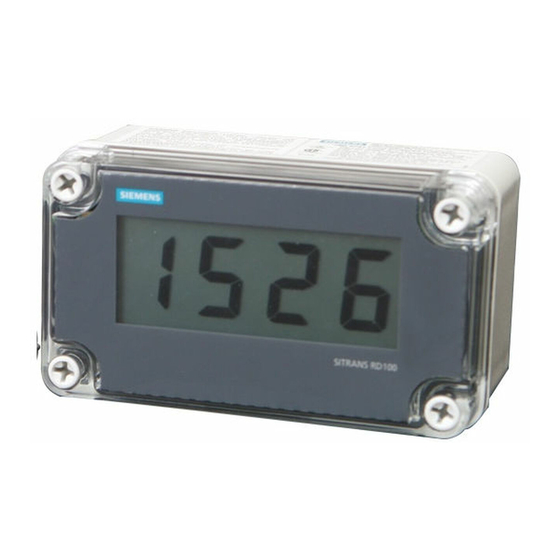
Summary of Contents for Siemens SITRANS RD100
- Page 2 The user is responsible for all changes and repairs made to the device by the user or the user’s agent. • All new components are to be provided by Siemens Milltronics Process Instruments. • Restrict repair to faulty components only.
-
Page 3: Safety Notes
Installation requirements • Setup instructions If you have any questions, comments, or suggestions about the manual content, please email us at techpubs.smpi@siemens.com. For the complete library of Siemens Milltronics manuals, go to www.siemens.com/processautomation. 7ML19985JU01 SITRANS RD100 – INSTRUCTION MANUAL Page 1... -
Page 4: Specifications
Specifications Except where noted, all specifications apply to operation at +25 °C (+77 °F). Note: Display • 1.0 " (25.4 mm) high LCD, numeric display range from -1000 to 1999 Enclosure • Impact-resistant glass-filled polycarbonate body • Color: gray • Impact-resistant clear polycarbonate cover: NEMA 4X, Type 4X, IP67 Mounting •... -
Page 5: Conversion Rate
Calibration • Two-step; non-interacting low and high Calibration Range • 4 mA input: display of -1000 to +1000 counts • 20 mA input: display of 4 mA count value +20 to 2000 counts, to a max. display of 1999 counts Accuracy •... -
Page 6: Wall Mounting
Mounting Wall Mounting wall mounting holes beneath cover screws SIDE VIEW FRONT VIEW Dimensions A: 80 mm (3.15") C: 60 mm (2.36") E: 65 mm (2.56") B: 140 mm (5.51") D: 120 mm (4.72") F: 20 mm (0.79") Wall mounting holes: Ø 4 mm (0.16") Weight: 340 g (12 oz) Page 4 SITRANS RD100 –... - Page 7 Optional Panel Mounting Kit mounting bracket self tapping screw washers panel mounting plate RD100 Notes • The optional panel mounting kit does not provide a NEMA 4X seal to panel. • Mounting brackets require 20 mm (0.8") clearance on either the top or the side of the meter for installation.
- Page 8 Connections Calibrator connected to input signal PCB display PCB component side (may be removed for bench calibration) LO calibration control HI calibration control balance control (factory adjust only) black S+ S- S- S+ loop jumper input signal PCB calibrated (mounted to base of enclosure) current source Control loop connected to input signal PCB input signal PCB...
- Page 9 Calibrator connected to display PCB display PCB component side calibrated current source The display PCB may be removed from the enclosure for bench calibration. Loop jumper must be installed on input signal PCB to maintain loop. Refer to Servicing display PCB outside the loop on page 9.
-
Page 10: Installation
Setup WARNINGS: • If any of the following operations are performed in the hazardous area, all appropriate hazardous area procedures must be followed. • To prevent damage to electronic components caused by electrostatic discharge, a grounding strap should be worn when servicing the display. -
Page 11: Loop Connections
further details. Wall mounting holes are located in each corner of the enclosure (see Mounting on page 4). Loop connections Control loop Disconnect power to the loop and install the meter as illustrated in connected to input signal PCB Removing display PCB from the loop on page 6 and page 9. - Page 12 *7ml19985JU01* Printed in Canada...


