Table of Contents
Advertisement
Advertisement
Table of Contents

Related Manuals for Asus P5Q SE Plus - Motherboard - ATX


Summary of Contents for Asus P5Q SE Plus - Motherboard - ATX
- Page 1 P5Q SE Plus...
- Page 2 Product warranty or service will not be extended if: (1) the product is repaired, modified or altered, unless such repair, modification of alteration is authorized in writing by ASUS; or (2) the serial number of the product is defaced or missing.
-
Page 3: Table Of Contents
Product highlights ............1-3 1.3.2 ASUS unique features ............ 1-4 1.3.3 ASUS Stylish features ............. 1-6 1.3.4 ASUS Intelligent Overclocking features ......1-6 Before you proceed ..............1-7 Motherboard overview ..............1-8 1.5.1 Placement direction ............1-8 1.5.2 Screw holes ..............1-8 1.5.3... -
Page 4: Contents
2.1.1 ASUS Update utility ............2-2 2.1.2 Creating a bootable floppy disk ........2-5 2.1.3 ASUS EZ Flash 2 utility ........... 2-6 2.1.4 AFUDOS utility ..............2-7 2.1.5 ASUS CrashFree BIOS 3 utility ........2-9 BIOS setup program ..............2-10 2.2.1... - Page 5 Contents 2.4.4 DRAM Timing Control ..........2-18 2.4.5 DRAM Static Read Control .......... 2-20 2.4.6 DRAM Read Training ........... 2-20 2.4.7 MEM. OC Charger ............2-20 2.4.8 Ai Clock Twister ............2-20 2.4.9 Ai Transaction Booster ..........2-21 2.4.10 CPU Voltage ............... 2-21 2.4.11 FSB Termination Voltage ..........
- Page 6 Contents Tools menu ................. 2-37 2.8.1 ASUS EZ Flash 2 ............2-37 2.8.2 Express Gate ..............2-38 2.8.3 AI NET 2................ 2-38 2.8.4 ASUS O.C. Profile ............2-39 Exit menu ..................2-40 Chapter 3: Software support Installing an operating system ........... 3-2 Support DVD information ............
-
Page 7: Notices
Notices Federal Communications Commission Statement This device complies with Part 15 of the FCC Rules. Operation is subject to the following two conditions: • This device may not cause harmful interference, and • This device must accept any interference received including interference that may cause undesired operation. -
Page 8: Safety Information
Safety information Electrical safety • To prevent electrical shock hazard, disconnect the power cable from the electrical outlet before relocating the system. • When adding or removing devices to or from the system, ensure that the power cables for the devices are unplugged before the signal cables are connected. If possible, disconnect all power cables from the existing system before you add a device. -
Page 9: About This Guide
Refer to the following sources for additional information and for product and software updates. ASUS websites The ASUS website provides updated information on ASUS hardware and software products. Refer to the ASUS contact information. Optional documentation Your product package may include optional documentation, such as warranty flyers, that may have been added by your dealer. -
Page 10: Conventions Used In This Guide
Conventions used in this guide To make sure that you perform certain tasks properly, take note of the following symbols used throughout this manual. DANGER/WARNING: Information to prevent injury to yourself when trying to complete a task. CAUTION: Information to prevent damage to the components when trying to complete a task. -
Page 11: P5Q Se Plus Specifications Summary
DDR2 1200 / 1066 / 800 / 667 MHz memory modules - Supports up to 16GB system memory • Refer to www.asus.com or this user manual for the memory QVL (Qualified Vendors List.) • Due to chipset limitation, when installing total memory of 4GB... - Page 12 Manageability WfM 2.0, DMI 2.0, WOL by PME, WOR by PME, PXE 8Mb Flash ROM, AMI BIOS, PnP, DMI 2.0, WfM 2.0, BIOS Features SM BIOS 2.3, ACPI 2.0a, ASUS EZ Flash 2, ASUS CrashFree BIOS 3 Drivers Support DVD...
-
Page 13: Chapter 1: Product Introduction
This chapter describes the motherboard features and the new technologies it supports. Chapter 1: Product introduction... -
Page 14: Welcome
® The motherboard delivers a host of new features and latest technologies, making it another standout in the long line of ASUS quality motherboards! Before you start installing the motherboard, and hardware devices on it, check the items in your package with the list below. -
Page 15: Special Features
Green ASUS This motherboard and its packaging comply with the European Union’s Restriction on the use of Hazardous Substances (RoHS). This is in line with the ASUS vision of creating environment-friendly and recyclable products/packaging to safeguard consumers’ health while minimizing the impact on the environment. -
Page 16: Asus Unique Features
ASUS EPU-4 Engine The new ASUS EPU - the world’s first power saving engine, has been upgraded to a new four-engine version, which provides total system power savings by detecting current PC loadings and intelligently moderating power in real-time. -
Page 17: Asus Quiet Thermal Solution
ASUS Quiet Thermal solution makes system more stable and enhances the overclocking capability. Fan Xpert ASUS Fan Xpert intelligently allows users to adjust both the CPU and chassis fan speed according to different ambient temperature, which is caused by different climate conditions in different geographic regions and system loading. -
Page 18: Asus Stylish Features
1.3.4 ASUS Intelligent Overclocking features AI Booster The ASUS AI Booster allows you to overclock the CPU speed in Windows environment without the hassle of booting the BIOS. Precision Tweaker This feature allows you to fine tune the CPU/memory voltage and gradually increase the memory Front Side Bus (FSB) and PCI Express frequency at 1MHz increment to achieve maximum system performance. -
Page 19: Before You Proceed
ON, in sleep mode, or in soft-off mode. This is a reminder that you should shut down the system and unplug the power cable before removing or plugging in any motherboard component. The illustration below shows the location of the onboard LED. ASUS P5Q SE Plus... -
Page 20: Motherboard Overview
Motherboard overview Before you install the motherboard, study the configuration of your chassis to ensure that the motherboard fits into it. Ensure to unplug the power cord before installing or removing the motherboard. Failure to do so can cause you physical injury and damage motherboard components. -
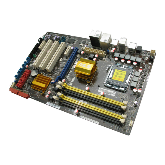
Page 21: Motherboard Layout
1.5.3 Motherboard layout Refer to 1.10 Connectors for more information about rear panel connectors and internal connectors. ASUS P5Q SE Plus... -
Page 22: Central Processing Unit (Cpu)
ASUS will shoulder the cost of repair only if the damage is shipment/transit-related. • Keep the cap after installing the motherboard. ASUS will process Return Merchandise Authorization (RMA) requests only if the motherboard comes with the cap on the LGA775 socket. -
Page 23: Installing The Cpu
135º angle. Load plate Lift the load plate with your thumb and forefinger to a 100º angle (4A), then push the PnP cap from the load plate window to remove (4B). ASUS P5Q SE Plus 1-11... - Page 24 Position the CPU over the socket, CPU notch ensuring that the gold triangle is on the bottom-left corner of the socket then fit the socket alignment key into the CPU notch. The CPU fits in only one correct orientation. DO NOT force the Gold triangle CPU into the socket to prevent...
- Page 25 Close the load plate (A), then push the load lever (B) until it snaps into the retention tab. ASUS P5Q SE Plus 1-13...
-
Page 26: Installing The Cpu Heatsink And Fan
1.6.2 Installing the CPU heatsink and fan The Intel LGA775 processor requires a specially designed heatsink and fan ® assembly to ensure optimum thermal condition and performance. thermal condition and performance. condition and performance. • When you buy a boxed Intel processor, the package includes the CPU fan ®... -
Page 27: Uninstalling The Cpu Heatsink And Fan
Rotate each fastener counterclockwise. Pull up two fasteners at a time in a diagonal sequence to disengage the heatsink and fan assembly from the motherboard. Carefully remove the heatsink and fan assembly from the motherboard. ASUS P5Q SE Plus 1-15... -
Page 28: System Memory
System memory 1.7.1 Overview The motherboard comes with four Double Data Rate 2 (DDR2) Dual Inline Memory Modules (DIMM) sockets. A DDR2 module has the same physical dimensions as a DDR DIMM but has a 240-pin footprint compared to the 184-pin DDR DIMM. DDR2 DIMMs are not notched differently to prevent installation on a DDR DIMM socket. -
Page 29: Memory Configurations
2.4 Ai Tweaker menu for manual memory frequency adjustment. • The memory modules may require a better cooling system to work stably under full loading (4 DIMMs) or overclocking setting. ASUS P5Q SE Plus 1-17... - Page 30 P5Q SE Plus Motherboard Qualified Vendors Lists (QVL) DDR2-1066 MHz capability DIMM support Chip Size Vendor Part No. Chip No. Brand Kingston KVR1066D2N7/1G Elpida E5108AJBG-1J-E • • • Kingston KHX8500D2/1G Kingston Heat-Sink Package • • • 512MB Kingston KHX8500D2/512 Kingston Heat-Sink Package •...
- Page 31 GEIL GL2L64M088BA30EB GEIL GB22GB6400C5DC • • • GEIL GL2L64M088BA30EB GEIL GB24GB6400C5QC • • • GEIL Heat-Sink Package GEIL GX22GB6400DC • • • GEIL Heat-Sink Package GEIL GE22GB800C4DC • • • (continued on the next page) ASUS P5Q SE Plus 1-19...
- Page 32 DDR2-800 MHz capability DIMM support Size Vendor Chip No. Chip Brand Part No. GEIL Heat-Sink Package GEIL GE24GB800C4QC • • • GEIL Heat-Sink Package GEIL GX22GB6400UDC • • • GEIL Heat-Sink Package GEIL GE22GB800C5DC • • • GEIL Heat-Sink Package GEIL GE24GB800C5QC •...
- Page 33 AD29608A8A-3EG80814 ADATA M2OAD5G314170Q1C58 • • • ADATA AD20908A8A-3EG 30724 ADATA M2OAD5H3J4170I1C53 • • • 512MB A3R12E3JFF717B9A00 AL6E8E63J-6E1 • • • A3R12E3JFF717B9A01 AL7E8E63J-6E1 • • • A3R1GE3CFF734MAA0J AL7E8F73C-6E1 • • • (continued on the next page) ASUS P5Q SE Plus 1-21...
- Page 34 Dual-channel memory configuration. • C*: Supports four modules inserted into both the yellow and black slots as two pairs of Dual-channel memory configuration. Visit the ASUS website for the latest DDR2-1066/800/667 MHz QVL. 1066/800/667 MHz QVL. MHz QVL. Chapter 1: Product introduction...
-
Page 35: Installing A Dimm
DIMM. Support the DIMM lightly with your fingers when pressing the retaining clips. The DIMM might get DIMM notch damaged when it flips out with extra force. Remove the DIMM from the socket. ASUS P5Q SE Plus 1-23... -
Page 36: Expansion Slots
Expansion slots In the future, you may need to install expansion cards. The following sub-sections describe the slots and the expansion cards that they support. Ensure to unplug the power cord before adding or removing expansion cards. Failure to do so may cause you physical injury and damage motherboard components. -
Page 37: Interrupt Assignments
– – PCI card 1 shared shared shared shared – – – – PCI card 2 shared shared shared shared – – – – PCI card 3 shared shared shared shared – – – – ASUS P5Q SE Plus 1-25... -
Page 38: Pci Slots
1.8.4 PCI slots The PCI slots support cards such as a LAN card, SCSI card, USB card, and other cards that comply with PCI specifications. Refer to the figure below for the location of the slots. 1.8.5 PCI Express x1 slots This motherboard supports PCI Express x1 network cards, SCSI cards and other cards that comply with the PCI Express specifications. -
Page 39: Jumpers
• Due to the chipset limitation, AC power off is required prior using C.P.R. function. You must turn off and on the power supply or unplug and plug the power cord before reboot the system. ASUS P5Q SE Plus 1-27... - Page 40 Keyboard power (3-pin KBPWR) This jumper allows you to enable or disable the keyboard wake-up feature. When you set this jumper to pins 2–3 (+5VSB), you can wake up the computer by pressing a key on the keyboard (the default is the Space Bar)s. This feature requires an ATX power supply that can supply at least 1A on the +5VSB lead, and a corresponding setting in the BIOS.
-
Page 41: 1.10 Connectors
Side Speaker Out port (gray). This port connects the side speakers in an 8-channel audio configuration. Refer to the audio configuration table on the next page for the function of the audio ports in 2, 4, 6, or 8-channel configuration. ASUS P5Q SE Plus 1-29... -
Page 42: Internal Connectors
Audio 2, 4, 6, or 8-channel configuration Headset Port 4-channel 6-channel 8-channel 2-channel Light Blue Line In Line In Line In Line In Lime Line Out Front Speaker Out Front Speaker Out Front Speaker Out Pink Mic In Mic In Mic In Mic In Orange... - Page 43 Ultra DMA cable connector. This prevents incorrect insertion when you connect the IDE cable. • Use the 80-conductor IDE cable for Ultra DMA 133/100/66 IDE devices. If any device jumper is set as “Cable-Select,” ensure that all other device jumpers have the same setting. ASUS P5Q SE Plus 1-31...
- Page 44 ICH10 Serial ATA connectors (7-pin SATA1-6) These connectors are for the Serial ATA signal cables for Serial ATA hard disk drives. right angle side Connect the right-angle side of SATA signal cable to SATA device. Or you may connect the right-angle side of SATA cable to the onboard SATA port to avoid mechanical conflict with huge...
- Page 45 These USB connectors comply with USB 2.0 specification that supports up to 480 Mbps connection speed. You can connect the front panel USB cable to the ASUS Q-Connector (USB, blue) first, and then install the Q-Connector (USB) to the USB connector onboard if your chassis supports front panel USB ports.
- Page 46 These are not jumpers! Do not place jumper caps on the fan connectors! Only the CPU_FAN and CHA_FAN connector support the ASUS Q-FAN feature. Serial port connector (10-1 pin COM1) This connector is for a serial (COM) port. Connect the serial port module cable to this connector, then install the module to a slot opening at the back of the system chassis.
- Page 47 AC'97 front panel audio module to this connector, set the item to [AC97]. By default, this connector is set to [HD Audio]. See section 2.5.3 Onboard Devices Configuration for details. ASUS P5Q SE Plus 1-35...
- Page 48 • If you are uncertain about the minimum power supply requirement for your system, refer to the Recommended Power Supply Waltage Calculator at http://support.asus.com/PowerSupplyCalculator/PSCalculator. aspx?SLanguage=en-us for details. Chapter 1: Product introduction 1-36...
-
Page 49: System Panel Connector
BIOS settings. Pressing the power switch for more than four seconds while the system is ON turns the system OFF. • Reset button (2-pin RESET) This 2-pin connector is for the chassis-mounted reset button for system reboot without turning off the system power. ASUS P5Q SE Plus 1-37... - Page 50 ASUS Q-Connector (system panel) You can use the ASUS Q-Connector to connect/disconnect chassis front panel cables in a few steps. Refer to the instructions below to install the ASUS Q-Connector. Connect the front panel cables to the ASUS Q-Connector. Refer to the labels on the Q-Connector...
-
Page 51: 1.11 Starting Up For The First Time
No VGA detected short beeps One continuous beep followed by four Hardware component failure short beeps At power on, hold down the <Delete> key to enter the BIOS Setup. Follow the instructions in Chapter 3. ASUS P5Q SE Plus 1-39... -
Page 52: 1.12 Turning Off The Computer
1.12 Turning off the computer 1.12.1 Using the OS shut down function If you are using Windows ® Click the Start button then select Turn Off Computer. Click the Turn Off button to shut down the computer. The power supply should turn off after Windows shuts down. -
Page 53: Chapter 2: Bios Setup
This chapter tells how to change the system settings through the BIOS Setup menus. Detailed descriptions of the BIOS parameters are also provided. Chapter 2: BIOS setup... -
Page 54: Managing And Updating Your Bios
ASUS Update: Updates the BIOS in Windows environment. ® ASUS EZ Flash 2: Updates the BIOS using a floppy disk or USB flash disk. ASUS AFUDOS: Updates the BIOS using a bootable floppy disk. ASUS CrashFree BIOS 3: Updates the BIOS using a bootable floppy disk, USB flash disk or the motherboard support DVD when the BIOS file fails or gets corrupted. - Page 55 To update the BIOS through the Internet: Launch the ASUS Update utility from the Windows desktop by clicking Start ® > Programs > ASUS > ASUSUpdate > ASUSUpdate. The ASUS Update main window appears. Select Update BIOS from the Select the ASUS FTP site nearest...
- Page 56 To update the BIOS through a BIOS file: Launch the ASUS Update utility from the Windows desktop by clicking Start ® > Programs > ASUS > ASUSUpdate > ASUSUpdate. The ASUS Update main window appears. Select Update BIOS from a file option from the drop-down menu, then click Next.
-
Page 57: Creating A Bootable Floppy Disk
Right-click Floppy Disk Drive then click Format to display the Format 3 1/2 Floppy dialog box. d. Select the Create an MS-DOS startup disk check box. e. Click Start. Copy the original or the latest motherboard BIOS file to the bootable floppy disk. ASUS P5Q SE Plus... -
Page 58: Asus Ez Flash 2 Utility
2.1.3 ASUS EZ Flash 2 utility The ASUS EZ Flash 2 feature allows you to update the BIOS without having to go through the long process of booting from a floppy disk and using a DOS-based utility. The EZ Flash 2 utility is built-in the BIOS chip so it is accessible by pressing <Alt>... -
Page 59: Afudos Utility
Updating the BIOS file To update the BIOS file using the AFUDOS utility: Visit the ASUS website (www.asus.com) and download the latest BIOS file for the motherboard. Save the BIOS file to a bootable floppy disk. ASUS P5Q SE Plus... - Page 60 A:\>afudos /iP5QSEPLU.ROM The utility verifies the file and starts updating the BIOS. A:\>afudos /iP5QSEPLU.ROM AMI Firmware Update Utility - Version 1.19(ASUS V2.07(03.11.24BB)) Copyright (C) 2002 American Megatrends, Inc. All rights reserved. WARNING!! Do not turn off power during flash BIOS Reading file ..done Reading flash ..
-
Page 61: Asus Crashfree Bios 3 Utility
2.1.5 ASUS CrashFree BIOS 3 utility The ASUS CrashFree BIOS 3 is an auto recovery tool that allows you to restore the BIOS file when it fails or gets corrupted during the updating process. You can update a corrupted BIOS file using the motherboard support DVD or a USB flash disk that contains the updated BIOS file. -
Page 62: Bios Setup Program
The BIOS setup screens shown in this section are for reference purposes only, and may not exactly match what you see on your screen. • Visit the ASUS website (www.asus.com) to download the latest BIOS file for this motherboard. Chapter 2: BIOS setup... -
Page 63: Bios Menu Screen
At the bottom right corner of a menu screen are the navigation keys for that particular menu. Use the navigation keys to select items in the menu and change the settings. Some of the navigation keys differ from one screen to another. ASUS P5Q SE Plus 2-11... -
Page 64: Menu Items
2.2.4 Menu items Main Ai Tweaker Advanced Power Boot Tools Exit The highlighted item on the menu Use [ENTER], [TAB], System Time [06:22:54] or [SHIFT-TAB] to System Date [Tue 09/02/2008] select a field. bar displays the specific items for Legacy Diskette A [1.44M, 3.5 in] Use [+] or [-] to SATA 1... -
Page 65: Main Menu
2.3.2 System Date [Day xx/xx/xxxx] Allows you to set the system date. 2.3.3 Legacy Diskette A [1.44M, 3.5 in.] Sets the type of floppy drive installed. Configuration options: [Disabled] [720K, 3.5 in.] [1.44M, 3.5 in.] ASUS P5Q SE Plus 2-13... -
Page 66: Sata 1-6
2.3.4 SATA 1–6 While entering Setup, the BIOS automatically detects the presence of IDE devices. There is a separate sub-menu for each IDE device. Select a device item then press <Enter> to display the IDE device information. BIOS SETUP UTILITY Main SATA 1 Select the type of... -
Page 67: Storage Configuration
Disables or enables device write protection. This will be effective only if device is accessed through BIOS. Configuration option: [Disabled] [Enabled] IDE Detect Time Out (Sec) [35] Selects the time out value for detecting ATA/ATAPI devices. Configuration options: [0] [5] [10] [15] [20] [25] [30] [35] ASUS P5Q SE Plus 2-15... -
Page 68: System Information
2.3.6 System Information This menu gives you an overview of the general system specifications. The BIOS automatically detects the items in this menu. BIOS SETUP UTILITY Main Bios Information Version : 0103 Build Date : 09/02/08 Processor Type : Intel(R) Core(TM)2 CPU 6300 @ 1.86GHz Speed : 1866 MHz Count... -
Page 69: Ai Tweaker Menu
FSB frequency. You can also type the desired CPU frequency using the numeric keypad. The values range from 200 to 800. Refer to the table below for the correct Front Side Bus and CPU External Frequency settings. ASUS P5Q SE Plus 2-17... -
Page 70: Fsb Strap To North Bridge
FSB/CPU External Frequency Synchronization Front Side Bus CPU External Frequency FSB 1600 400 MHz FSB 1333 333 MHz FSB 1066 266 MHz FSB 800 200 MHz PCIE Frequency [Auto] Allows you to set the PCI Express frequency. Use the <+> and <-> keys to adjust the PCIE frequency. - Page 71 Configuration options: [Auto] [1 DRAM Clocks] – [15 DRAM Clocks] WRITE to READ Delay(D) [Auto] Configuration options: [Auto] [1 DRAM Clocks] – [15 DRAM Clocks] READ to READ Delay(S) [Auto] Configuration options: [Auto] [1 DRAM Clocks] – [15 DRAM Clocks] ASUS P5Q SE Plus 2-19...
-
Page 72: Dram Static Read Control
READ to READ Delay(D) [Auto] Configuration options: [Auto] [1 DRAM Clocks] – [15 DRAM Clocks] WRITE to WRITE Delay(S) [Auto] Configuration options: [Auto] [1 DRAM Clocks] – [15 DRAM Clocks] WRITE to WRITE Delay(D) [Auto] Configuration options: [Auto] [1 DRAM Clocks] – [15 DRAM Clocks] 3rd Information: 13-5-1-5-5 The values vary depending on your settings of the following sub-items: WRITE to PRE Delay [Auto]... -
Page 73: Ai Transaction Booster
Allows you to set the Memory voltage. The values range from 1.80V to 2.30V with a 0.10V interval. 2.4.13 North Bridge Voltage [Auto] Allows you to set the North Bridge voltage. The values range from 1.10V to 1.40V* with a 0.10V interval. ASUS P5Q SE Plus 2-21... -
Page 74: South Bridge Voltage
• Setting the CPU Voltage, FSB Termination Voltage, Memory Voltage and North Bridge Voltage items to a high level may damage the chipset, memory module and CPU permanently. Proceed with caution. • The system may need better cooling system to work stably under high voltage settings. -
Page 75: Advanced Menu
(C)Copyright 1985-2008, American Megatrends, Inc. CPU Ratio Setting [Auto] Allows you to adjust the ratio between CPU Core Clock and FSB Frequency. Use the <+> and <-> keys to adjust the value. Configuration options: [Auto] [06.0] [07.0] [08.0] ASUS P5Q SE Plus 2-23... - Page 76 C1E Support [Enabled] Allows you to enable or disable Inter CPU Enhanced Halt (C1E) function, a CPU power-saving function in system halt state. When enable, the CPU core frequency and voltage will be reduced during the system halt state to decrease power consumption.
-
Page 77: Chipset
Allows you to enable or disable the Memory Hole. Configuration options: [Disabled] [15MB-16MB] Initiate Graphic Adapter [PEG/PCI] Allows you to decide which graphics controller to use as the primary boot device. Configuration options: [PCI/PEG] [PEG/PCI] ASUS P5Q SE Plus 2-25... -
Page 78: Onboard Devices Configuration
2.5.3 OnBoard Devices Configuration BIOS SETUP UTILITY Advanced Onboard Device Configuraiton Enable or Disable High Definition Audio High Definition Audio [Enabled] Controller Front Panel Type [HD Audio] J-Micron eSATA/PATA Controller [Enabled] Onboard PCIE LAN [Enabled] Onboard PCIE LAN Boot ROM [Disabled] Serial Port1 Address [3F8/IRQ4]... -
Page 79: Usb Configuration
USB devices at startup. If detected, the USB controller legacy mode is enabled. If no USB device is detected, the legacy USB support is disabled. Configuration options: [Disabled] [Enabled] [Auto] ASUS P5Q SE Plus 2-27... -
Page 80: Pci Pnp
2.5.5 PCI PnP The PCI PnP menu items allow you to change the advanced settings for PCI/PnP devices. Take caution when changing the settings of the PCI PnP menu items. Incorrect field values can cause the system to malfunction. BIOS SETUP UTILITY Advanced Advanced PCI/PnP Settings NO: lets the BIOS... -
Page 81: Power Menu
Allows you to enable or disable the Advanced Configuration and Power Interface (ACPI) support in the Advanced Programmable Interrupt Controller (APIC). When set to Enabled, the ACPI APIC table pointer is included in the RSDT pointer list. Configuration options: [Disabled] [Enabled] ASUS P5Q SE Plus 2-29... -
Page 82: Apm Configuration
2.6.5 APM Configuration BIOS SETUP UTILITY Power APM Configuration <Enter> to select whether or not to Restore on AC Power Loss [Power Off] restart the system after AC power loss. Power On By RTC Alarm [Disabled] Power On By External Modems [Disabled] Power On By PCI Devices [Disabled]... -
Page 83: Hardware Monitor
N/A. CPU Q-Fan Control [Disabled] Allows you to enable or disable the CPU Q-Fan controller. Configuration options: [Disabled] [Enabled] The CPU Fan Profile item appears when you enable the CPU Q-Fan Control feature. ASUS P5Q SE Plus 2-31... - Page 84 CPU Fan Profile [Standard] Allows you to set the appropriate performance level of the CPU Q-Fan. When set to [Standard], the CPU fan automatically adjusts depending on the CPU temperature. Set this item to [Silent] to minimize fan speed for quiet CPU fan operation, or [Turbo] to enable slight quiet operation for heavy-loading computing.
-
Page 85: Boot Menu
These items specify the boot device priority sequence from the available devices. The number of device items that appears on the screen depends on the number of devices installed in the system. Configuration options: [1st FLOPPY DRIVE] [Hard Drive] [ATAPI CD-ROM] [Disabled] ASUS P5Q SE Plus 2-33... -
Page 86: Boot Settings Configuration
Allows you to enable or disable the full screen logo display feature. Configuration options: [Disabled] [Enabled] Set this item to [Enabled] to use the ASUS MyLogo 2™ feature. Add On ROM Display Mode [Force BIOS] Sets the display mode for option ROM. Configuration options: [Force BIOS] [Keep... -
Page 87: Security
Real Time Clock (RTC) RAM. See section “2.6 Jumpers” for information on how to erase the RTC RAM. After you have set a supervisor password, the other items appear to allow you to change other security settings. ASUS P5Q SE Plus 2-35... -
Page 88: Change User Password
BIOS SETUP UTILITY Boot <Enter> to change Security Settings password. <Enter> again to Supervisor Password :Installed disabled password. User Password :Installed Change Supervisor Password User Access Level [Full Access] Change User Password Clear User Password Password Check [Setup] User Access Level [Full Access] This item allows you to select the access restriction to the Setup items. -
Page 89: Tools Menu
2.8.1 ASUS EZ Flash 2 Allows you to run ASUS EZ Flash 2. When you press <Enter>, a confirmation message appears. Use the left/right arrow key to select between [Yes] or [No], then press <Enter> to confirm your choice. See section 2.1.3 for details. -
Page 90: Express Gate
2.8.2 Express Gate [Enabled] Allows you to enable or disable Express Gate.Configuration options: [Disabled] [Enabled] Enter OS Timer [10 Seconds] Allows you to set the countdown duration that the system waits at the Express Gate’s first screen before starting Windows or other installed OS. Configuration options: [Prompt User] [1 Second] [3 Seconds] [5 Seconds] [10 Seconds] [15 Seconds] [20 Seconds] [30 Seconds] Reset User Data [No]... -
Page 91: Asus O.c. Profile
This function can support devices such as USB flash disk or floppy disk with FAT 32/16 format and single partition only. • DO NOT shut down or reset the system while updating the BIOS to prevent the system boot failure! ASUS P5Q SE Plus 2-39... -
Page 92: Exit Menu
Exit menu The Exit menu items allow you to load the optimal or failsafe default values for the BIOS items, and save or discard your changes to the BIOS items. BIOS SETUP UTILITY Main Ai Tweaker Advanced Power Boot Tools Exit Exit system setup Exit &... -
Page 93: Chapter 3: Software Support
This chapter describes the contents of the support DVD that comes with the motherboard package. Chapter 3: Software support... -
Page 94: Installing An Operating System
The contents of the support DVD are subject to change at any time without notice. Visit the ASUS website(www.asus.com) for updates. 3.2.1 Running the support DVD Place the support DVD to the optical drive. The DVD automatically displays the Drivers menu if Autorun is enabled in your computer. -
Page 95: Drivers Menu
The drivers menu shows the available device drivers if the system detects installed devices. Install the necessary drivers to activate the devices. ASUS InstAll - Installation Wizard for Anti-Virus and Drivers Utility Launches the ASUS installation wizard for anti-virus and drivers utility. -
Page 96: Utilities Menu
Installs all of the utilities through the Installation Wizard. ASUS Update ® The ASUS Update utility allows you to update the motherboard BIOS in Windows environment. This utility requires an Internet connection either through a network or an Internet Service Provider (ISP). - Page 97 ASUS PC Probe II This smart utility monitors the fan speed, CPU temperature, and system voltages, and alerts you of any detected problems. This utility helps you keep your computer in healthy operating condition. ASUS AI Suite An innovative application to do overclocking, fan control, power saving and quiet thermal control.
-
Page 98: Manual Menu
Reader from the Support DVD before opening a user manual ® ® file. 3.2.5 ASUS Contact information Click the Contact tab to display the ASUS contact information. You can also find this information on the inside front cover of this user guide. Chapter 3: Software support... -
Page 99: Other Information
DVD. Click an icon to display the specified information. Motherboard Info Displays the general specifications of the motherboard. Browse this DVD Displays the support DVD contents in graphical format. ASUS P5Q SE Plus... -
Page 100: Technical Support Form
Technical support Form Displays the ASUS Technical Support Request Form that you have to fill out when requesting technical support. Chapter 3: Software support...