Table of Contents
Advertisement
Quick Links
Owner's Manual
t CRgFTSMRN" J
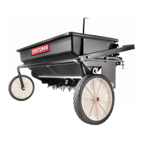
32" SPIKER SPREADER
Model No. 486.24331
CAUTION:
Before using this product,
read this manual and follow
all Safety Rules and
Operating Instructions.
• Safety
• Assembly
• Operation
• Maintenance
• Parts
Sears, Roebuck and Co., Hoffman Estates, IL 60179 U.S.A.
www.sears.com/craftsman
PRINTED IN U.S.A.
FORM
NO. 48070
(2/O1)
Advertisement
Table of Contents

Related Manuals for Craftsman 486.24331


Summary of Contents for Craftsman 486.24331
- Page 1 • Assembly Before using this product, • Operation read this manual and follow • Maintenance all Safety Rules and • Parts Operating Instructions. Sears, Roebuck and Co., Hoffman Estates, IL 60179 U.S.A. www.sears.com/craftsman PRINTED IN U.S.A. FORM NO. 48070 (2/O1)
-
Page 2: Limited One-Year Warranty
MAINTENANCE ............SAFETY RULES ............STORAGE ..............FULL SIZE HARDWARE CHART ......4 REPAIR PARTS ILLUSTRATION ......14 CARTON CONTENTS ..........REPAIR PARTS LIST ..........ASSEMBLY ..............OPERATION ............PARTS ORDERING/SERVICE ....Back Page LIMITED ONE YEAR WARRANTY For one year from the date of purchase, when this Spiker Spreader is maintained and lubricated according to the operating and maintenance instructions in the owner's manual, Sears will repair any defect in material or workmanship free of... - Page 3 Any power equipment can cause injury if operated improperly or if the user does not understand how to operate the equipment. Exercise caution at all times, when using power equipment. • Read this owner's manual before attempting • Wear eye and hand protection when handling and using lawn chemicals.
- Page 4 SHOWN FULL SIZE NOT SHOWN FULL SIZE REF. QTY. DESCRIPTION REF. QTY. DESCRIPTION Hex Bolt, 1/2" x 4" Flat Washer, 5/8" Hex Bolt, 5/16" x 2-1/4" Lockwasher, 1/2" Hex Bolt, 5/16" x 2" Cotter Pin, 1/8" x 1-1/2" Hex Bolt, 5/16" x 1-3/4" Cotter Pin, 3/32"...
- Page 5 CARTON CONTENTS 5. Hitch Tube (2) 9. Wheel (2) 1. Chain Cover Lift Handle 10. Transport Tube Assembly 2. Flow Control Lever Spike Disk (7) 11. Hitch Bracket (2) 3. Center Brace Drive Disk Assembly (2) 12. Spiker Shaft Assembly 4.
-
Page 6: Tools Required For Assembly
• Assemble the grip onto the lift handle. See figure 2. TOOLS REQUIRED FOR ASSEMBLY • On the right side, insert a 5/16" x 1-3/4" hex bolt through a 5/16" flat washer and then through the rear (2) 7/16" Wrenches hole in the hopper and the hitch tube. -
Page 7: Hitch Pin
• Fasten the hitch tubes together using three 5/16" x 2-1/4" hex bolts and 5/16" hex lock nuts. DO not tighten yet. See figure 4. TRANSPORT TUBE 5/16" HEX WASHER LOCK NUT (3) I_"LOCK I_"HEX WASHER JAM NUT 5116"x 2-114" 1/2"... - Page 8 • Place the flow control lever into the slot in the • Place a nylon washer onto the bent end of the flow hopper. See figure 8. control link and then insert the end of the link into the • Place the center brace into the hopper.
- Page 9 • Push a flange bearing into each of the seven drive • Place a plastic spacer tube, a 5/8" flat washer, a disks, from the side shown in figure 12. drive disk, a 5/8" flat washer, another drive disk and a third 5/8" flat washer onto the shaft. Fit the plastic spacer tube onto the flanged bearing in the end plate.
-
Page 10: Compression Spring
• Place a 5/8" flat washer, the compression spring • Place two 5/8" flat washers separated by a metal and another 5/8" flat washer onto the shaft. See spacer tube onto the shaft. See figure 18. figure 16. 5/8" FLAT WASHER COMPRESSION SPRING... -
Page 11: Cotter Pin
• Place a 5/8" flat washer onto the end of the spike disk • Place two 5/8" flat washers separated by a metal shaft and secure the shaft with a 1/8" x 1-1/2" cotter spacer tube onto the shaft. See figure 20. pin. - Page 12 KNOW YOUR SPIKER SPREADER Read this owner's manual and safety rules before operating your Spiker Spreader. Compare the illustration below with your Spiker Spreader to familiarize yourself with the various controlsand their locations. PLASTIC WING NUT LIFT HANDLE FLOW CONTROL LEVER Opens and closes the flow PLASTIC WING NUT Tightens...
-
Page 13: Operating Tips
FLOW RATE CHART • For easiest application, first apply material across both ends of the area. Two or three passes on each end are sufficient. Then apply material back Flow Rate Setting MATERIAL TYPE At 3 M.P.H. and forth as shown. Use the end areas for turning around, shutting off the spreader as you enter the Light Heavy... - Page 15 REFo PART DESCRIPTION REF. PART DESCRIPTION NO.I 47931 47959 Link, Flow Control Hopper 24736 47969 Endp!ate, Right Hand Ferrule, 5/16" Thread x 1/4" Hole 24735 43224 Endplate, Left Hand Bolt, Hex 5/16" x 2-1/4" 43882 44180 Rivet, Stainless Bolt, Hex 5/16" x 2" 24747 Brace, Center 43840...
- Page 16 Get it fixed, at your home or ours! For repair of major brand appliances in your own home... no matter who made it, no matter who sold _t! 1-800-4-MY-HOM E sM Anyt,me, day or ntght (1-800-469-4663) www.sears.com To bring in products such as vacuums, lawn equipment and electronics for repair, call for the location of your nearest Sears Parts &...