Table of Contents
Advertisement
Available languages
Available languages
I (RRFTSMRN1
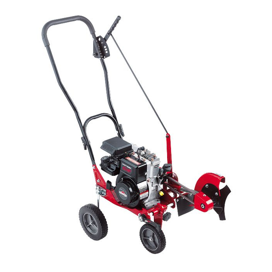
Operator's
Manual
Edger/Trimmer
4 Horsepower
9 Inch Blade
Model 536.772341
CAUTION: Before using
this product, read this
manual and follow all of its
Safety Rules and
Operating Instructions.
Manual del usario
0rilladora/ Recortadora
4 caballos
de fuerza (hp)
Cuchilla de 9 pulgadas
Modelo 536.772341
PRECAUCION: Antes de usar este
producto, lea este manual y siga
todas las normas de seguridad e
instrucciones de operaci6n.
Sears, Roebuck
and Co., Hoffman
Estates,
IL 60179 U.S.A.
F_)21103C
www.sears.com/craftsman
Advertisement
Table of Contents

Related Manuals for Craftsman 536.772341


Summary of Contents for Craftsman 536.772341
- Page 1 (hp) Cuchilla de 9 pulgadas Modelo 536.772341 PRECAUCION: Antes de usar este producto, lea este manual y siga todas las normas de seguridad e instrucciones de operaci6n. Sears, Roebuck and Co., Hoffman Estates, IL 60179 U.S.A. F_)21103C www.sears.com/craftsman...
-
Page 2: Warranty
WARRANTY ON CRAFTSMAN EDGER For two years from the date of purchase, when this Craftsman Edger is maintained, lubri- cated, and tuned up according to the operating and maintenance instructions in the owner's manual, Sears will repair, free of charge, any defect in material or workmanship. -
Page 3: Safety Rules
SAFETY RULES Safe Operation Practices Edger. WARNING: Look for this symbol to point out important safety precautions. It means: "Attention! Become Alert! Your Safety Is Involved." Operating Safety tal starting when setting-up, • Never allow children or young teenagers to ARNING: To prevent acciden- transporting,... - Page 4 SAFETY RULES prevent accidental starting. Thoroughly Safe Storage spect the Edger for any damage, and re- • Always refer to the owner's manual instruc- pair the damage before restarting and tions for important details if the Edger is to operating it. be stored for an extended period.
-
Page 5: International Symbols
SAFETY RULES INTERNATIONAL SYMBOLS IMPORTANT: Many of the following symbols are located on your unit or on literature sup- plied with the product. Before you operate the unit, learn and understand the purpose for each symbol. Control And Operating Symbols Slow Fast Fuel... -
Page 6: Assembly
ASSEMBLY ASSEMBLY Parts Packed Separately In Carton 1 - Owner's Manual (not shown) 1 -HairPin 1 - Container Of Oil 1 - Container of Oil 1 - Hair Pin REMOVE EDGER glasses or eye shields while as, FROM CARTON WARNING: Always wear safety sembling the Edger. -
Page 7: How To Raise The Handle
ASSEMBLY HOW TO RAISE THE HANDLE Insert the end of the control rod from Loosen the knobs and raise the upper handle to the upright position. See left to right through the hole in the quill Figure 2. Allow the control rod to swing support arm. -
Page 8: How To Prepare The Engine
ASSEMBLY HOW TO PREPARE THE ENGINE Fill With Oil How To Add The Engine This Edger was shipped with a container of 1. Put the Edger on a level surface. SAE30 motor oil. Add this oil to the engine 2. Remove the oil fill cap (Figure 5). before operating. - Page 9 ASSEMBLY _" CHECKLIST For the best performance and satisfaction from this quality product, please review the following checklist before you operate the Edger: #-" All assembly instructions have been completed. Check carton. Make sure no loose parts remain in the carton. All fasteners have been propedy tight- ened.
-
Page 10: Know Your Edger
OPERATION KNOW YOUR EDGER READ THE OWNER'S MANUAL AND ALL SAFETY RULES BEFORE YOU OPERATE the Edger. To familiarize yourself with the location of the controls, compare the illustrations with your Edger. Save this manual for future reference. ENGINE Throttle Clutch Lever Control Rod VIEW OF BLADE AREA... -
Page 11: How To Use The Throttle Control
OPERATION HOW TO STOP THE EDGER Emergency Stopping To immediately stop the engine and the blade, move the throttle control to the STOP position. Normal Stopping First, move the clutch lever back to the DIS- ENGAGED position. Then, move the throttle control to SLOW, then to STOP (if Figure 7... -
Page 12: How To Use The Index Lever
OPERATION HOW TO USE THE INDEX LEVER Stop the engine and disconnect the spark plug wire from the spark plug. Loosen the front wheel knob shown in Figure 10. Slide the front wheel all the way to the right side. Front Wheel Knob Securely tighten the front wheel knob. - Page 13 OPERATION HOW TO USE THE CURB-HOPPING FEATURE wheel until the front wheel is level with Because the front wheel and the right rear wheel are adjustable, the Edger can be used the left rear wheel and the unit is setting on uneven surfaces, such as the curb shown on the curb as shown in Figure 13.
-
Page 14: How To Stop The Engine
OPERATION HOW TO STOP THE ENGINE 6. Move the choke control lever to the Emergency Stopping CHOKE position (Figure 14). To immediately stop the engine and the blade, move the throttle control to the STOP 7. To start engine, hold the recoil starter position. -
Page 15: Edging Tips
OPERATION EDGING TIPS • Edging is best performed when conditions are dry. If the soil is to wet, dirt becomes packed around the blade causing prema- ture belt wear and decreased perfor- mance. • If dirt does become packed around the blade, stop the engine and remove the wire from the spark plug. -
Page 16: Maintenance
MAINTENANCE DATE OF PURCHASE: SERVICE RECORDS Fill in dates as you Before Every Every Before complete regular Each Each Before SERVICE service. Often Hours Hours Season Storage DATES Lubricate All Pivot Points Lubricate Wheel Axles Check Engine Oil Level Change Engine Oil Replace Air Cleaner Filter Check Spark Plug... - Page 17 MAINTENANCE LUBRICATION Remove the oil fill cap. Fill the engine crankcase. Pour slowly. Do not overfill. After each 25 hours, apply a small amount of See "Product Specifications" for amount engine oil to all moving parts, particularly the and type of oil. Install the oil fill cap. wheels.
-
Page 18: Service And Adjustment
MAINTENANCE SPARK PLUG Check the spark plug every 25 hours. Re- moval. Tighten the spark plug to a torque place the spark plug if the electrodes are of 15 foot-pounds. pitted, burned, or if the porcelain is cracked. Feeler Gauge Make sure the spark plug is clean. -
Page 19: How To Remove The Belt
SERVICE AND ADJUSTMENT HOW TO REMOVE THE BELT The belt made of a special compound, if the Loosen, do not remove, the screw that belt becomes worn or breaks, replace the holds the belt guide. Then, move the belt with an original equipment belt. belt guide away from the belt. -
Page 20: How To Replace The Blade
SERVICE AND ADJUSTMENT HOW TO REPLACE THE BLADE The blade is subject to wear and damage, Disconnect the spark plug wire from the such as nicks and dents. This will not gener- spark plug. ally affect its function. Remove the blade Iocknut that holds The blade is designed to not require sharp- the blade to the drive shaft. - Page 21 SERVICE AND ADJUSTMENT STORAGE parts such as the carburetor, fuel filter, fuel hose, and tank during storage. Also, Edger indoors with fuel in the WARNING: Never store the fuel tank. Never store in an en- using alcohol-blended fuels (called gaso- hol, ethanol or methanol) can attract closed, poorly ventilated area where...
- Page 22 TROUBLE SHOOTING CHART TROUBLE CAUSE CORRECTION Stale fuel Drain fuel tank. Fill with fresh Engine difficult to start fuel. Clogged fuel filter Replace fuel filter Dirt in fuel tank or out of fuel Clean fuel tank. Engine runs erratically Take unit to a Sears Service Carburetor out of adjustment Center.
- Page 23 SEARS, ROEBUCK Federal and California Emission Control Systems Limited Warranty Small Off-Road Engines CALIFORNIA & US EPA EMISSION quired maintenance listed in your Owner's Manual, but Sears, Roebuck and Co. will not CONTROL WARRANTY STATEMENT deny warranty solely due to the lack of receipts The U.
-
Page 24: Emission Control System Warranty
ershall pay any charges formaking service Sears, Roebuck and Co. according to Subsec- calls and/or fortransporting theproducts to tion 4 below. such part repaired or re- and from the place w here the inspection and/ placed under Warranty shall orwarranty work i sperformed. - Page 25 use shall not r educe Sears, Roebuck and Co. EMISSION-RELATED PARTS ECS Warranty obligations. INCLUDE THE FOLLOWING: 9.Unapproved add-on ormodified parts m ay 1. Carburetor Assembly and its Internal Com- not b eused t omodify orrepair aSears, Roe- ponents buck a nd Co. engine. Such u se voids this ECS a) Fuel filter Warranty and shall besufficient grounds for...
- Page 26 CRAFTSMAN 536.772341 REPAIR PARTS _j22 323095 F DESCRIPTION PARTNO. DESCRIPTION PARTNO. 4 HP 95212-0138-E1 Cover, E nginePulley 331281-201 (See Enginepages) Screw,5/16-24x3.00 181624 Plate,EngineSpacer 1701036 Spacer,Sleeve 315095 Screw,3/8-16xl .O0 25x6 Screw,5/16-24x3.75 173030 Pulley 1701015 Spacer 308237 Screw,Set 120580 Spacer,Sleeve 315095 Belt, 4L 32.60"...
- Page 27 CRAFTSMAN 536.772341 REPAIR PARTS _163 157_ 331765 E DESCRIPTION PARTNO. DESCRIPTION PARTNO. FrontWheelArm 339299-201 Knob,Rectangle 20252 FrontCurbHopper 740132 Flatwasher 22265 Pushnut, Washer 338614 45905 PlasticWasher 325892 Screw,5/16-18x.63 51333 Spacer,HeightAdjust 331421 Plate,HeightAdjust 331394-281 Pin, Spring 32x81 Knob, Molded 339388 Lever,HeightAdjust 331419...
- Page 28 CRAFTSMAN 536.772341 REPAIR PARTS 323179 F PARTNO. DESCRIPTION PARTNO. DESCRIPTION Bracket,CurbHop Mnt 6842 Spacer,Sleeve 45222 Flatwasher 120393 Screw,5/16-18x.75 180077 Nut,5/16-18 1498 71294 Knob, W ing5/16-18 310896 Bolt,5/16-18x2.00 126380 Rod,WheelSupport Clevis 8082 F_021103C...
- Page 29 CRAFTSMAN 536.772341 REPAIR PARTS 323129 E PARTNO. PARTNO. DESCRIPTION NO. DESCRIPTION Flatwasher 710083 338070 Quill Assembly Quill Support 338656-201 Lever, I ndex 308466 308254 308155 Bolt,3/8-16 Spring,Torsion Flatwasher 120396 Nut, 5/16-18 1498 1499 Flatwasher 22265 Nut,3/8-16 Rubber Deflector 308243 740296...
- Page 30 CRAFTSMAN 536.772341 REPAIR PARTS 343718 A PARTNO. PARTNO. DESCRIPTION DESCRIPTION 315288 Screw,5/16-18x.63 51333 Bolt,5/16-18xl.75 Control Rod 71294 580292-853 Knob, W ing5/16-18 LowerHandle 740127-853 HairPin 36368 1498 HairPin 36368 Nut,5/16-18 F=021103C...
- Page 31 CRAFTSMAN 536.772341 REPAIR PARTS 323136 F DESCRIPTION PARTNO. DESCRIPTION PARTNO. UpperHandle 740147 Spring,Compression 25644 SelectorPlate 310052-853 Nut,5/16-18 1498 Screw,1/4-20xl.25 180024 Grip, Hand 56924 Nut, 1/4-20 782585 Stud 310053 DepthAdjustHandle 310050-853 Nut,3/8-16 1499 Screw,5/16-18x1.25 180081 F=O21103C...
- Page 32 CRAFTSMAN 536.772341 REPAIR PARTS 343720B DESCRIPTION PARTNO. DESCRIPTION PARTNO. Nut,3/8-16 1499 Nut,5/16-18 15x88 Spacer, S leeve 310715 113 Spacer, S leeve 51887 Bolt, HHSH3/8 310716 114 Tire& Rim 336546 Tire&Rim 336545 116 Tire& Rim 336545 Screw,5/16-18x3.08 180113 Flatwasher 17X91 Flatwasher...
- Page 33 CRAFTSMAN 536.772341 REPAIR PARTS 332247 EE DESCRIPTION PARTNO. DESCRIPTION PARTNO, BladeGuard 331076-201 Screw,1/4-20x,50 710264 Bolt,Carriage 2x53 Cover, Q uillPulley 53405-201 Nut,5/16-18 15x88 Screw,10-16x,50 26x245 Guide,BeltFront 326748-201 DECALS DESCRIPTION PARTNO. Decal,AngleIndicator 48x1177 Decal,Danger RotatingBlade 333874 Decal,DangerInformation 48x1195 Decal,QuadrantSelector 312548 Decal,Logo 48x1178...
- Page 34 ENGINE 95212-0138-E1 REPAIR PARTS 358 ENGINE GASKET KIT 51 _ 163_ 191@ 529J_ 529A 1095 VALVE GASKET SET 51 _ 163 @ 529 _ 529A10 _, 527_ 718A 1019 LABEL KIT [1058 OWNER'S MANUAL] F-021103C...
- Page 35 ENGINE 95212-0138-E1 REPAIR PARTS KEY PART PART DESCRIPTION DESCRIPTION 494549 298908 Pin-Piston Cylinder Assembly 399269 (.005" Oversize) Kit-Bushing/Seal Rod-Connecting (Magneto Side) 294367 *299819 Seal-Oil (Standard) Note (Magneto Side) 296079 Rod-Connecting 690386 Head-Cylinder (.020" Undersize) *0692288 Gasket-Cylinder Head 691719 Dipper-Connecting 495774 Breather Assembly 691664 Screw...
- Page 36 ENGINE 95212-0138-E1 REPAIR PARTS 842 _ 287 _' 523 _ 524 O 957 0 121 CARBURETOR OVERHAUL 191_ 163 (_) 394f_ 365_ 718B_. 97_,_.,__ 435 _ 1149_ '_'_} 434 _ 212_0j 987 @ f_b, 130 _ 95" 394 _,_) 987Ae _ 432 /_ 393 _ 1273_...
- Page 37 ENGINE 95212-0138-E1 REPAIR PARTS KEY PART PART DESCRIPTION DESCRIPTION *692218 Gasket-Crankcase 692200 Screw (.015" Thick, Standard) (Fuel Tank) Note 190A 691687 Screw *270895 Gasket (Fuel Tank) (.005" Thick) e.692241 Gasket-Fuel Tank *270896 Gasket 691693 Screw (.009" Thick) (Dipstick Tube) 497506 Cover_rankcase 690953 Screw...
- Page 38 ENGINE 95212-0138-E1 REPAIR PARTS 356,,,,_'_h_ 188"_ -_78 _ 780_ 201_ 823@¢ 456_. 689 _'_ 459_ 163 _' 1036 EMISSION LABEL F-021103C...
- Page 39 ENGINE 95212-0138-E1 REPAIR PARTS KEY PART PART DESCRIPTION DESCRIPTION 496893 Flywheel 691236 Cup-Flywheel 690463 Guard-Flywheel 692299 Plate-Pawl Friction 692144 Housing-Rewind 281505 PawI-Rachet Starter 694420 Ring-Rotating Trim 692259 Rope-Starter 494279 Cleaner-Air (Cut to Required 690800 Length) (Rewind Starter) 691915 Grip-Starter Rope 691696 Screw 690837 Screw...
- Page 40 GARANTiA LIMITADA DE DOS AI_IOS PARA LA ORILLADORA CRAFTSMAN Esta oriIladora Craftsman esta garantizada pot dos afios a partir de la fecha de compra, siem- prey cuando se le haya dado mantenimiento, lubricaci6n y aflnado de acuerdo con las instruc- clones de operaci6n y mantenimiento que aparecen en el manual del usuado, Sears reparar&,...
-
Page 41: Normas De Seguridad
NORMAS DE SEGURIDAD Pr&cticas de seguridad pars la operacibn de la orilladora. DVERTENCIA: Busque este simbolo clue le indicarb puntos importantes de precaucibn para su seguridad. Este simbolo quiere decir: "lAtencibn! iEst_ alerta! Se trata de su seguridad". Operacibn el arranque accidental cuando ADVERTENCIA: Para prevenir... - Page 42 NORMAS DE SEGURIDAD • Tome todas las precauciones posibles Reparacion / Ajustes cuando deje la orilladora desatendida. Si golpea un objeto extraSo, con la unidad, Apague el motor. apague el motor. Desconecte el cable de la • No sobrecargue la capacidad de la orilla- bujia y mant_ngalo alejado de 6sta para dora al tratar de rebordear a mucha profun-...
- Page 43 NORMAS DE SEGURIDAD SiMBOLOS INTERNACIONALES IMPORTANTE: La mayoria de los simbolos siguientes se encuentran en Ia unidad o en la informacibn que viene con el producto. Antes de usar la unidad, familiaricese con el signifi- cado de cada uno de los simbolos. Simbolos de control y funcionamiento Marcha lenta Marcha rapida...
- Page 44 ENSAMBLAJE ENSAMBLAJE Contenido de la bolsa de piezas 1 -Manual del usuario (no aparece en la figura) 1 - Botella de aceite 1 - Horquilla 1 - Horquilla 1 - Botella de aceite INSTRUCCIONES PARA SACAR LA ORILLADORA DE SU CAJA gafas / anteojos de seguridad ADVERTENCIA: Siempre use...
- Page 45 ENSAMBLAJE COMO LEVANTAR EL MANGO 1. Afloje las perillas y levante el mango de izquierda a derecha a trav6s del agu- superior a la posici6n vertical. Figura 22. jero en en brazo hueco de soporte. Su- Deje que la vara de control cuelgue li- jete con la horquilla que viene en la bremente.
- Page 46 ENSAMBLAJE COMO PREPARAR EL MOTOR Cbmo ahadir el aceite de motor 1. Coloque la orilladora sobre una superficie Cbmo Ilenar el cbrter con aceite plana. Esta orilladora fue enviada con una botella 2. Saque la tapa / varilla indicadora de aceite de motor SAE30. A_ada este acei- (Figura 25).
- Page 47 ENSAMBLAJE _" LISTA DE COMPROBACION Para obtener un rendimiento 6ptimo y la ma- yor satisfacci6n de este producto de alta ca- Iidad, favor de revisar la siguiente lista de comprobaci6n antes de hacer funcionar su orilladora: Se hart completado todas las instruc- ciones de ensamblaje.
- Page 48 OPERACION CONOZCA SU ORILLADORA ANTES DE HACER FUNCIONAR LA ORILLADORA, LEA EL MANUAL DEL USUARIO Y TO- DA LA INFORMACI6N SOBRE SEGURIDAD. Para famiiiarizarse con la ubicaci6n de los con- troles, compare las siguientes ilustraciones con su orilladora. Guarde este manual para referencias futuras.
- Page 49 OPERACI()N COMO DETENER LA motor, o hacia abajo para aminorada (Figura 28). ORILLADORA Parada de emergencia Para parar de inmediato eI motor y la cuchi- Palanca de Ila mueva la palanca de control de acelera- ci6n a la posici6n PARADA. Parada normal Primero, mueva la palanca de embrague hacia atr&s hasta la posici6n DESENGAN-...
- Page 50 OPERACI()N COMO USAR LA PALANCA DE REGLAJE 1. Apague el motor y desconecte el cable de la bujia. Afloje la perilla de la rueda delantera que se muestra en la Figura 30. Deslice completamente la rueda delantera cia el lado derecho. Apriete bien la perilla de la rueda de- Perilla de la Iantera.
- Page 51 OPERACI()N COMO USAR LA FUNCIONALIDAD DE ABORDILLADO Dado que se pueden ajustar la rueda delan- Baje la rueda delantera hasta que _sta tera y la rueda trasera derecha, la orilladora se encuentre al mismo nivel que la rue- puede usarse en superficies desiguales da trasera izquierda y la orilladora quede les como el bordillo mostrado en Ia situada en el bordillo como en Ia...
- Page 52 OPERACION COMO PARAR EL MOTOR 7. Para arrancar el motor, agarre firmemente Parada de emergencia la manija de arranque manual con su ma- Para parar el motor y la cuchiIIa de inmedia- no derecha. to, mueva el control de aceleraci6n a la posi- 8.
- Page 53 OPERACION RECOMENDACIONES PARA EL USO DE SU ORILLADORA • La orilladora trabaja mejor cuando el tiem- po esta seco. Si la tierra esta muy moja- da, el barro se pega y acumula alrededor de la cuchilla haciendo que 6sta se des- gaste prematuramente y que la unidad no funcione como debe.
-
Page 54: Mantenimiento
MANTENIMIENTO FECHA DE COMPRA: REGISTR0 DE SERVICl0 Antes Anote las fechas a medi- Antes Csda Cada deca- Antes FECHAS da que comp!ete cads deca- A me- dses- servlclo, dsuso nudo horas horss tacibn guardsr SERViCI0 Lubricar todos los puntos de gi_ Lubricar Ios ejes de las ruedas del motor... - Page 55 MANTENIMIENTO LUBRICACIC)N Quite la tapa del aceite. Llene lenta- mente el carter del motor. No Io Ilene de- Despu_s de cada 25 horas de use, aplique masiado. Consulte las "Especificaciones unas gotas de aceite de motor a todas Ias del producto" para obtener informaci6n piezas movibles, especialmente alas rue- sobre la cantidad y grado de aceite.
-
Page 56: Ajuste Del Carburador
MANTENIMIENTO BUJiA Revise la bujia cada 25 horas de operaci6n, para facilitar su remoci6n. Apriete la bu- Reemplace Ia bujia si los electrodos seen- jia hasta Iograr un par de torsi6n de 15 cuentran daSados e quemados, o si Ia por- Iibras-pie. -
Page 57: Servicio Y Ajustes
SERVICIO Y AJUSTES COMO SACAR LA CORREA La correa esta hecha de un matedal espe- Afloje, pero no quite, el tornillo que su- cial. Si la correa se desgasta o se rompe, jeta la guia de la correa. Separe la reemplacela con una correa de repuesto ori- guia de la correa de Ia correa. - Page 58 SERVICIO Y AJUSTES COMO REEMPLAZAR LA CUCHILLA La cuchilla esta sujeta a desgaste y daSos, Para reemplazar la cuchilla, sigas los pasos a continuaci6n. tales como hendeduras y abolladuras. Gene- ralmente _stas no afectan su funcionamien- Desconecte el cable de la bujia. Retire la contratuerca de Ia cuchilla La cuchilla esta dise_ada de manera que no...
- Page 59 SERVICIO AJUSTES ALMACENAMIENTO ponentes del sistema de combustible, la orilladora con combustible Ies como el carburador, filtro de DVERTENCIA: Nunca guarde combustible, linea de combustible y tan- en el tanque en un recinto ca- que, durante el almacenamiento de la uni- rrado.
- Page 60 TABLA DE LOCALIZACION DE AVERiAS PROBLEMA CAUSA SOLUCI(SN El motor arranca con Combustible vi_o Vacfe el tanque de combustible. Ll_nelo con dificultad combustible fresco. Filtro de combustible Reemplace el filtro de obstruido combustible. Suciedad en el tanque de Limpie el tanque de El motor marcha de forma combustible...
- Page 61 SEARS, ROEBUCK Garantia limitada de cumplimiento con el Sistema Federal de control de emisiones y con el sistema de control de emisiones del Estado de California Motores peque_os para vehiculos todo terreno CONTROL DE EMISIONES DE SISTEMA PARA EL CONTROL DE CALIFORNIA Y DE LA AGENCIA DE EMISIONES DEL FABRICANTE - COBERTURA...
-
Page 62: Nota Importante
Sears, Roebuck and Co. o a Sears, Roebuck A. CAMPO DE APLICACION: Esta garantia and Co. al 1-800-473-7247 (llamada gratuita deber& aplicarse a los motores pequeSos para en E.U.A.). vebiculos todo terreno modelo 1995 y mode- los de aSos posteriores en California (para otros estados, motores modelo 1997 y mode-... - Page 63 Garantia SCE debera garantizarse pot e l r esto aprobada pot Sears, Roebuck and Co. para del P eriodo delamisma. utilizarse en el desempeSo de cualquier man- tenimiento o cambio de la Garantia SCE, la 3.Cualquier parte g arantizada yrelacionada cual se proporcionara sin cargo alguno para el con emisiones que seespecifique...
- Page 64 _ii_ii;,i,iii Your Home For repair in your home of all major brand appliances, _iiiiiiiiiiiii? lawn and garden equipment, or heating and cooling systems, iiiiiiiiiiii no matter who made it, no matter who sold it! iiiiiiiiiiii For the replacement parts, accessories iiiiiiiiiiii iiiiiiiiiiii owner s manuals that you need to do-it-yourself.