Table of Contents
Advertisement
Available languages
Available languages
Operator's
Manual
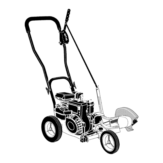
Edger
4 Horsepower
9 Inch Blade
Model 536.772340
CAUTION: Before using
this product, read this
manual and follow all of its
Safety Rules and
Operating Instructions.
- CRRFTSMRN °
Manual del usario
Orilladora
4 caballos
de fuerza
(hp)
de 9 pulgada
I&mina
Modelo
536.772340
PRECAUCI6N:
Antes de usar este
producto, lea este manual y siga
todas las reglas de seguridad e
instrucciones de operaci6n.
Sears, Roebuck
and Co., Hoffman
Estates,
IL 60179 U.S.A.
F-021102L
www.sears.com/craftsman
Advertisement
Table of Contents

Related Manuals for Craftsman 536.772340


Summary of Contents for Craftsman 536.772340
- Page 1 (hp) de 9 pulgada I&mina Modelo 536.772340 PRECAUCI6N: Antes de usar este producto, lea este manual y siga todas las reglas de seguridad e instrucciones de operaci6n. Sears, Roebuck and Co., Hoffman Estates, IL 60179 U.S.A. www.sears.com/craftsman F-021102L...
-
Page 2: Warranty
Sears will repair, free of charge, any defect in material or workmanship. If this Craftsman Edger is used for commercial or rental purposes, this warranty applies for only 90 days from the date of purchase. -
Page 3: Safety Rules
SAFETY RULES Safe Operation Practices Edger. WARNING: Look for this symbol to point out important safety precautions. It means: "Attention! Become Alert! Your Safety Is Involved." Operating Safety tal starting when setting-up, ARNING: To prevent acciden- Never allow children or young teenagers to transporting, adjusting or mak- operate the Edger. - Page 4 SAFETY RULES spect the Edger for any damage, and re- Safe Storage pair the damage before restarting and • Always refer to the owner's manual instruc- operating it. tions for important details if the Edger is to be stored for an extended period. If Edger should start to vibrate abnormally, stop engine and check immediately for the...
- Page 5 SAFETY RULES INTERNATIONAL SYMBOLS IMPORTANT: Many of the following symbols are located on your unit or on literature sup- plied with the product. Before you operate the unit, learn and understand the purpose for each symbol. Control And Operating Symbols Slow Fast Fuel...
-
Page 6: Assembly
ASSEMBLY ASSEMBLY Parts Packed Separately In Carton 1 - Owner's Manual (not shown) 1 - Hair Pin 1 - Container Of Oil 1 - Container of Oil 1 - Hair Pin REMOVE THE EDGER FROM THE CARTON glasses or eye shields while as, WARNING: Always wear safety sembling the Edger. -
Page 7: How To Raise The Handle
ASSEMBLY HOW TO RAISE THE HANDLE Insert the end of the control rod from Loosen the knobs and raise the upper handle to the upright position. See left to right through the hole in the quill Figure 2. Allow the control rod to swing support arm. -
Page 8: How To Prepare The Engine
ASSEMBLY HOW TO PREPARE THE ENGINE Fill With Oil How To Add The Engine 1. Put the Edger on a level surface. This Edger was shipped with a container of SAE30 motor oil. Add this oil to the engine 2. Remove the oil fill cap (Figure 5). before operating. - Page 9 ASSEMBLY _- CHECKLIST For the best performance and satisfaction from this quality product, please review the following checklist before you operate the Edger: All assembly instructions have been completed. Check carton. Make sure no loose parts remain in the carton. All fasteners have been properly tight- ened.
-
Page 10: Know Your Edger
OPERATION KNOW YOUR EDGER READ THE OWNER'S MANUAL AND ALL SAFETY RULES BEFORE YOU OPERATE the Edger. To familiarize yourself with the location of the controls, compare the illustrations with your Edger. Save this manual for future reference. ENGINE Throttle Clutch Lever Control Rod Choke... -
Page 11: How To Use The Throttle Control
OPERATION HOW TO STOP THE EDGER Move the clutch lever back to the DIS- Clutch Lever ENGAGED position. Then, move the throttle control to SLOW, then to STOP (if equipped) See Figure 7. WARNING: Never leave the EDGER unattended while the engine is running. -
Page 12: How To Use The Index Lever
OPERATION HOW TO USE THE INDEX LEVER 1. Stop the engine and disconnect the spark plug wire from the spark plug. Loosen the front wheel knob shown in Figure 10. Slide the front wheel all the way to the right side. Securely tighten the front wheel knob. - Page 13 OPERATION HOW TO USE THE CURB-HOPPING FEATURE wheel until the front wheel is level with Because the front wheel and the right rear wheel are adjustable, the Edger can be used the left rear wheel and the unit is setting on uneven surfaces, such as the curb shown on the curb as shown in Figure 12.
-
Page 14: How To Stop The Engine
OPERATION HOW TO STOP THE ENGINE 1. To stop the engine, move the clutch lever 9. Quickly pull the recoil starter handle. DO all the way back to the DISENGAGED NOT allow the starter rope to snap back. position. Let the starter rope slowly rewind. If en- gine fails to start after three pulls, push 2. -
Page 15: Edging Tips
OPERATION EDGING TIPS • Edging is best performed when conditions are dry. If the soil is to wet, dirt becomes packed around the blade causing prema- ture belt wear and decreased perfor- mance. • If dirt does become packed around the blade, stop the engine and remove the wire from the spark plug. -
Page 16: Maintenance
MAINTENANCE CUSTOMER RESPONSIBILITIES SERVICE RECORDS Fill in datesas you Every Every Before Before Before SERVICE completeregular Each Each service, Often Hours Hours Season Storage DATES Lubricate Wheel Axles Change Engine Oil Check Spark Plug Tighten All Fasteners Lubricate Quill Rod/ tube PRODUCT SPECIFICATIONS GENERAL RECOMMENDATIONS... - Page 17 MAINTENANCE LUBRICATION Remove the oil fill cap (see Figure 14). Fill the engine crankcase. Pour slowly. After each 25 hours, apply a small amount of Do not overfill. See "Product Specifica- engine oil to all moving parts, particularly the tions" for amount and type of oil. Install wheels.
-
Page 18: Spark Plug
MAINTENANCE SPARK PLUG Check the spark plug every 25 hours. Re- moval. Tighten the spark plug to a torque place the spark plug if the electrodes are of 15 foot-pounds. pitted, burned, or if the porcelain is cracked. Feeler Gauge Make sure the spark plug is clean. -
Page 19: Service And Adjustment
SERVICE AND ADJUSTMENT HOW TO REMOVE THE BELT The belt made of a special compound. If the Loosen, do not remove, the screw that belt becomes worn or breaks, replace the holds the belt guide. Then, move the belt with an original equipment belt. belt guide away from the belt. -
Page 20: How To Replace The Blade
SERVICE AND ADJUSTMENT HOW TO REPLACE THE BLADE Disconnect the spark plug wire from the The blade is subject to wear and damage, such as nicks and dents. This will not gener- spark plug. ally affect its function. Remove the blade Iocknut that holds the blade to the drive shaft. - Page 21 SERVICE AND ADJUSTMENT STORAGE parts such as the carburetor, fuel filter, fuel hose, and tank during storage. Also, Edger indoors with fuel in the WARNING: Never store the fuel tank. Never store in an en- using alcohol-blended fuels (called gaso- hol, ethanol or methanol) can attract closed, poorly ventilated area where moisture which leads to separation...
- Page 22 TROUBLE SHOOTING CHART TROUBLE CAUSE CORRECTION Drain fuel tank. Fill with fresh Engine difficult to start Stale fuel fuel. Clogged fuel filter Replace fuel filter Dirt in fuel tank or out of fuel Clean fuel tank. Engine runs erratically Take unit to a Sears Service Carburetor out of adjustment Center.
-
Page 23: Sears, Roebuck And Co
SEARS, ROEBUCK AND CO. Federal and California Emission Control Systems Limited Warranty Small Off-Road Engines CALIFORNIA & US EPA EMISSION quired maintenance listed in your Owner's Manual, but Sears, Roebuck and Co. will not CONTROL WARRANTY STATEMENT deny warranty solely due to the lack of receipts The U. -
Page 24: Emission Control System Warranty
ershall pay any charges formaking service Sears, Roebuck and Co. according to Subsec- calls and/or fortransporting theproducts tion 4 below. Any such part repaired or re- and from the place w here the inspection and/ placed under the ECS Warranty shall be orwarranty work i sperformed. - Page 25 use shall not r educe Sears, Roebuck and Co, EMISSION-RELATED PARTS ECS Warranty obligations. INCLUDE THE FOLLOWING: 9.Unapproved add-on ormodified parts m ay 1. Carburetor Assembly and its Internal Com- not b eused t omodify orrepair aSears, Roe- ponents buck a nd Co. engine. Such u se voids this ECS a) Fuel filter Warranty and shall besufficient grounds for...
- Page 26 CRAFTSMAN 536.772340 REPAIR PARTS 323095 F DESCRIPTION PARTNO. PARTNO, DESCRIPTION 4 HP 95212-0138-E1 331281-201 Cover,EnginePulley (SeeEnginepages) 181624 Screw,5/16-24x3.00 47792 Screw,3/8-16xl .00 315095 Spacer,Sleeve 1701004 Pulley 173030 Screw,5/16-24x3.75 2001022 Key,Square 308237 Spacer 120580 Screw,Set 315095 Spacer,Sleeve 32668 V-Belt, 4L 323534-201 Assembly,Frame 578733 Screw5/16-24xl .00...
- Page 27 CRAFTSMAN 536.772340 REPAIR PARTS 157_ 331765 E PARTNO. DESCRIPTION PARTNO. DESCRIPTION 150 339299-201 FrontWheelArm 20252 Knob,Rectangle 22265 Flatwasher 740132 FrontCurbHopper 45905 152 338614 Pushnut, W asher 153 325892 PlasticWasher 51333 Screw,5/16-18x.63 154 331421 Spacer,HeightAdjust 331394-201 Plate,HeightAdjust 155 332002 Pin,Spring 339388...
- Page 28 CRAFTSMAN 536.772340 REPAIR PARTS 323179 F DESCRIPTION PARTNO, DESCRIPTION PARTNO, 6842 Bracket, CurbHopMnt 182 45222 Spacer,Sleeve Flatwasher 180077 Screw,5/16-18x.75 120393 1498 Nut,5/16-18 184 71294 Knob,Wing5/16-18 126380 Bolt,5/16-18x2.00 186 310896 Rod,WheelSupport 8082 Clevis F-O21102L...
- Page 29 CRAFTSMAN 536.772340 REPAIR PARTS 323129 E DESCRIPTION PARTNO. DESCRIPTION NO. PARTNO. 120396 Flatwasher 338070 QuillAssembly 308466 Lever, I ndex 338656-201 QuillSupport 308155 308254 Bolt,3/8-16 Spring,Torsion 710083 Flatwasher 1498 Nut,5/16-18 22265 Flatwasher 1499 Nut,3/8-16 308243 RubberDeflector 740296 Blade,Edger 46023 710271 Screw,10-16xl.50...
- Page 30 CRAFTSMAN 536.772340 REPAIR PARTS "_ 343718 A DESCRIPTION PARTNO. NO. PARTNO. DESCRIPTION 315288 Bolt,5/16-18xl .75 51333 Screw,5/16-18x.63 71294 580292-853 ControlRod Knob,Wing5/16-18 740127-853 LowerHandle 36368 HairPin 36368 HairPin 1498 Nut,5/16-18 F-O21102L...
- Page 31 CRAFTSMAN 536.772340 REPAIR PARTS 323136 F PARTNO. DESCRIPTION PARTNO. DESCRIPTION 1701016 UpperHandle 25644 Spring,Compression 310052-853 SelectorPlate 1498 Nut, 5/16-18 180024 Screw,1/4-20xl.25 56924 Grip,Hand 310053 Stud 782585 Nut, 1/4-20 1499 Nut, 3/8-16 310050-853 DepthAdjustHandle 180081 Screw,5/16-18xl.25 315995 Grip,FoamTubing F-O21102L...
- Page 32 CRAFTSMAN 536.772340 REPAIR PARTS 343720B DESCRIPTION PARTNO. DESCRIPTION PARTNO. 15x88 1499 Nut,3/8-16 Nut,5/16-18 113 51887 105 310715 Spacer,Sleeve Spacer,Sleeve 114 336546 Tire & Rim 106 310716 Bolt, H HSH3/8 108 336545 Tire& Rim 116 336545 Tire& Rim 17X91 Flatwasher 180113 Screw,5/16-18x3.00...
- Page 33 CRAFTSMAN 536.772340 REPAIR PARTS 332247 E DESCRIPTION PARTNO. DESCRIPTION PARTNO. 710264 Screw, 1/4-20x.50 331076-201 Blade, G uard 53405-201 Cover, Quill P ulley 2x53 Bolt, C arriage 710271 Screw, 10-16x.50 15x88 Nut,5/16-18 326748-201 Guide, BeltFront DECALS PARTNO. DESCRIPTION DESCRIPTION PARTNO. 48x1177...
-
Page 34: Repair Parts
ENGINE 95212-0138-E1 REPAIR PARTS 358 ENGINE GASKET KIT 163_ 529A _ 1095 VALVE GASKET SET 308' 529 _ 529A10 _ 527_ _o7. 1019 LABEL KIT [ 1058 OWNER'S MANUAL F-021102L... - Page 35 ENGINE 95212-0138-E1 REPAIR PARTS KEY PART PART DESCRIPTION DESCRIPTION 494549 Cylinder Assembly 298908 Pin-Piston 399269 Kit-BushingtSeal (.005" Oversize) (Magneto Side) 294367 Rod-Connecting _299819 Seal-Oil (Standard) Note (Magneto Side) 296079 Rod-Connecting 690386 Head--Cylinder (,020" Undersize) 7 _692288 Gasket-Cylinder Head 691719 Dipper-Connecting 495774 Breather Assembly 691664...
- Page 36 ENGINE 95212-0138-E1 REPAIR PARTS 842 _ 287 _ 524 _C) 121 CARBURETOR OVERHAUL 190A 191 __._ 163_2_ 394_ 365 _ 718B %. 97_\ 435 _ 689 _ 51 )_"_ r2_J,_ 130 _ 95 _ 394 ,_4_._ 987A@_ "_ j_._ 393 _-_ 6_$7 __"_'27 r_r-L"m _ 110A F-O21102L...
- Page 37 REPAIR PARTS ENGINE 95212-0138-E1 PART PART DESCRIPTION DESCRIPTION 692200 Screw _692218 Gasket-Crankcase (Fuel Tank) (.015" Thick, Standard) Note 190A 691687 Screw _270895 Gasket (Fuel Tank) e_692241 Gasket-Fuel Tank (.005" Thick) _270896 Gasket 691693 Screw (.009" Thick) (Dipstick Tube) 497506 Cover-Crankcase 690953 Screw 692020...
- Page 38 ENGINE 95212-0138-E1 REPAIR PARTS 356 _ 621 ,_ 216_ 780 _:_ 883' 459_ 1210 592_ 1036 EMISSION LABEL F-O21102L...
- Page 39 ENGINE 95212-0138-E1 REPAIR PARTS KEY PART PART DESCRIPTION DESCRIPTION 496893 Flywheel 691236 Cup-Flywheel 692299 Plate-Pawl Friction 690463 Guard-Flywheel 281505 Pawl-Rachet 692144 Housing-Rewind Starter 694420 Ring-Rotating Trim 494279 Cleaner-Air 692259 Rope-Starter 690800 (Cut to Required Length) (Rewind Starter) 691696 Screw 691915 Grip-Starter Rope 690837...
-
Page 40: Sears, Roebuck And Co., D817Wa, Hoffman Estates, Il
GARANTIA LIMITADA DE DOS AI_IOS PARA LA ORILLADORA CRAFTSMAN Esta orilladora Craftsman est_ garantizada por dos aSos a partir de la fecha de compra, siem- prey cuando, se le haya dado mantenimiento, lubricaci6n y afinado de acuerdo con las ins- trucciones de operaci6n y mantenimiento que aparecen en el manual del usuado, Craftsman reparar&... -
Page 41: Normas De Seguridad
NORMAS DE SEGURIDAD Pr_cticas de seguridad para la operacibn de la orilladora. ADVERTENCIA: Busque este sfmbolo que le indicarb puntos importantes de precaucibn para su seguridad. Este simbolo quiere decir: <'iAtencibn! iEstd alerta! Su seguridad estd en peligro". Nunca guarde la orilladora Ilena de com- bustible ni el recipiente de combustible el arranque accidental de la mb-... - Page 42 NORMAS DE SEGURIDAD • Nunca ponga en marcha un motor dentro laridad todos los sujetadores para mante- de un recinto o de un _rea cerrada. Los nerlos debidamente apretados. vapores del escape son peligrosos, ya que contienen MON6XlDO DE CARBONO, Reparacibn / Ajustes UN GAS INODORO Y MORTAL.
- Page 43 NORMAS DE SEGURIDAD SJMBOLOS INTERNACIONALES IMPORTANTE: La mayoria de los simbolos siguientes se encuentran en la unidad o en la informacibn que viene con el producto. Antes de usar la unidad, familiaricese con el signifi- cado de cada uno de los simbolos. Simbolos de control y funcionamiento Combustible Aceite...
-
Page 44: Montaje
ENSAMBLAJE MONTAJE Contenido de la boisa de parties 1 - Manual del usuario (no aparece en ta figura) 1 - Botella de aceite 1 - Horquilla 1 - Horquilla 1 - Botella de aceite INSTRUCCIONES PAPA SACAR LA ORILLADORA DE SU CAJA gafas I anteojos de seguridad ADVERTENCIA: Siempre use... - Page 45 ENSAMBLAJE C6MO LEVANTAR EL MANGO 1. Afloje las perillas y levante el mango de izquierda a derecha a trav_s del agu- superior a la posici6n vertical. Ver la jero en en brazo hueco de soporte. Su- Figura 21. Deje que la vara de control jete con la horquilla que viene en la cuelgue libremente.
- Page 46 ENSAMBLAJE PREPARACI6N DEL MOTOR 1. Coloque la orilladora sobre una superficie plana Cbmo Ilenar el c&rter de aceite 2. Saque la varilla indicadora (Figura 24). Esta orilladora fue enviada con una botella 3. Llene lentamente el c_rter del motor. NO de aceite de motor SAE30.
-
Page 47: Piezas De Repuesto
ENSAMBLAJE _" LISTA DE COMPROBACION Para obtener un rendimiento 6ptimo y la ma- yor satisfacci6n de este producto de alta ca- lidad, favor de revisar la siguiente lista de comprobaci6n antes de hacer funcionar su orilladora: _" Verifique que se han completado das las instrucciones de montaje. - Page 48 OPERACION CONOZCA SU ORILLADORA ANTES DE HACER FUNCIONAR LA ORILLADORA, LEA EL MANUAL DEL USUARIO Y TO- DA LA INFORMACION SOBRE SEGURIDAD. Para famUiarizarse con la ubicaci6n de los con- troles, compare las siguientes ilustraciones con su orilladora. Guarde eete manual para refereneias futuras.
- Page 49 OPERACION C6MO DETENER LA ORILLADORA Palanca de embrague Mueva la palanca de embrague hacia atr_s hasta la posici6n DESENGAN- CHADA. Luego, mueva el control del acelerador a la posici6n de IDLE o SLOW, si es posible. Ver la Figura 26. ORILLADORA desatendida DVERTENCIA:...
- Page 50 OPERACION COMO USAR LA PALANCA DE REGLAJE 1, Apague el motor y desconecte el cable de la bujia, Afloje la perilla de la rueda delantera que se muestra en la Figura 29, Deslice completamente la rueda delantera ha- cia el lado derecho, Apriete bien la perilla de la rueda de- lantera.
- Page 51 OPERACION C6MO USAR LA FUNCIONALIDAD DE ABORDILLADO Baje la rueda delantera hasta que _sta Dado que se pueden ajustar la rueda delan- tera y la rueda trasera derecha, la orilladora se encuentre al mismo nivel que la rue- puede usarse en superficies desniveladas, da trasera izquierda y la orilladora quede tales como el bordillo mostrado en la...
- Page 52 OPERACION COMO PARAR EL MOTOR 1. Para apagar el motor, suelte la palanca de 8. Sujete firmemente el mango de la orillado- parada del motor. ra con su mano izquierda. 2. Si el motor continea encendido, mueva la 9. Jale r_pidamente la manija de arranque palanca de control del acelerador hacia...
- Page 53 OPERACION RECOMENDACIONES PARA EL USO DE SU ORILLADORA • La orilladora trabaja mejor cuando el tiem- po est_ seco. Si la tierra est_ muy moja- da, el barro se pega y acumula alrededor de la cuchilla haciendo que _sta se des- gaste prematuramente y que la unidad no funcione como debe.
-
Page 54: Mantenimiento
MANTENIMIENTO RESPONSABILIDADES DEL USUARIO REGISTRO DESERVICIO Anotelasfechasa medi- FECHAS da que completecada servicio, SERVICl0 Lubricar la varilla/tubo hue- ESPEClFICACIONES RECOMENDACIONES PRODUCTO GENERALES La garantia de esta Orilladora no cubre pie- Modelo No.: 536.772340 zas que hayan sido sometidas a abuso o Fecha de compra: negligencia por parte del usuario. - Page 55 MANTENIMIENTO LUBRICACI6N Quite la tapa del aceite (ver la Figura 33). Llene lentamente el c_rter de Despu6s de cada 25 horas de uso, aplique motor. No Io Ilene demasiado. Consulte unas gotas de aceite de motor a todas las las "Especificaciones del producto"...
-
Page 56: Ajuste Del Carburador
MANTENIMIENTO BUJ|A Revise la bujia cada 25 horas de operaci6n jia hasta Iograr un par de torsi6n de 15 de la unidad. Debe reemplazar la bujia si los libras-pie. electrodos se encuentran dafiados o quema- dos, o si la porcelana est_ fisurada. L_mina calibradora 0,030 pulg. - Page 57 SERVICIO Y AJUSTES C6MO DESMONTAR LA CORREA La correa est_ hecha de un material espe- Afloje, pero no quite, el tornillo que su- cial. Si la correa se desgasta o se rompe, jeta la guia de la correa. Separe la reempl_cela con un repuesto original, guia de la correa de la correa.
- Page 58 SERVICIO Y AJUSTES C6MO REEMPLAZAR LA CUCHILLA La cuchilla est_ sujeta a desgaste y da_os, Desconecte el cable de la bujia. tales como hendeduras y abolladuras. Gene- ralmente _stas no afectan el funcionamiento Retire la contratuerca de cuchilla que de la unidad. sujeta la cuchilla al eje motor.
-
Page 59: Servicio Y Ajustes
SERVICIO AJUSTES ALMACENAMIENTO ponentes del sistema de combustible, la orilladora con combustible les como el carburador, filtro del ADVERTENCIA: Nunca guarde combustible, linea del combustible y tan- en el tanque en un recinto ce- que, durante el almacenamiento de la uni- rrado. - Page 60 TABLA DE LOCALIZACION DE AVERIAS PROBLEMA CAUSA SOLUCI6N El motor no arranca o Combustible viejo Vacie el tanque de combustible. LI6nelo con arranca con dificultad combustible fresco. Filtro de combustible Reemplace el filtro de obstruido combustible. Suciedad en el tanque de Limpie el tanque de El motor marcha de forma combustible...
- Page 61 SEARS, ROEBUCK AND CO. Garantia limitada de cumplimiento con el Sistema Federal de control de emisiones y con el sistema de control de emisiones del Estado de California Motores pequefios no aptos para carretera (off-road) CONTROL DE EMISIONES SISTEMA PARA EL CONTROL DE CALIFORNIA Y DE LA AGENCIA DE EMISIONES DEL FABRICANTE -...
-
Page 62: Nota Importante
Sears, Roebuck and Co. o a Sears, Roebuck A. CAMPO DE APLICACI6N: Esta garantia deber_ aplicarse a los motores pequeSos para and Co. al 1-800-473-7247 (llamada gratuita en E.U.A.). vehiculos off-road modelo 1995 y modelos de aSos posteriores en California (para otros es- NOTA IMPORTANTE tados, motores modelo 1997 y modelos de aSos posteriores). - Page 63 Garantia SCE deber_ garantizarse por e lresto aprobada por S ears, Roebuck and Co. p ara del P eriodo delamisma. utilizarse eneldesempeSo decualquier man- tenimiento ocambio delaGarantia SCE, la 3.Cualquier parle g arantizada yrelacionada cual seproporcionar_ sin cargo alguno para e l con emisiones que seespecifique para c am-...
- Page 64 For repair of major brand appliances in your own home,.. no matter who made it, no matter who sold it} (1-800-469-4663) www_sears,com To bring in products such as vacuums, lawn equipment:and e!ect_onics for repairi call for the location of your nearest Sears Parts & Repair Center, 1-800-488-1222 _y_im_, ,igh_...