Table of Contents
Advertisement
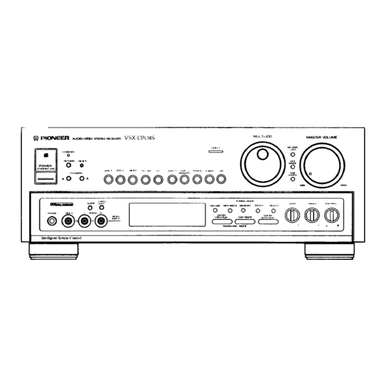
AUDIO/VIDEO
STEREO
RECEIVER
VSX-D704S
55bBo oB 66
I
lhank you for buying this Pioneer product.
Please read through these operating instructions so you will
know how to operate your model properly. After you have
finished reading the instructions,
put them away in a safe
place for future reference.
In some countries
or regions, the shape of the power plug
and power outlet may sometimes differ from that shown in
the explanatory
drawings.
However,
the
method
of
connecting and operating the unit is the same.
IMPORTANT
NOTICE
(For
U.S.
and Canadian
models)
The serial number for this equipment
is located on the
rear panel,
Please write this serial number
on your
enclosed warranty card and keep it in a secure area. This
is for your security,
(For Canadian
model)
CAUTION:
TO PREVENT ELECTRIC SHOCK DO NOT USE
THIS (POLARIZED) PLUG WITH AN EXTENSION
CORD,
RECEPTACLEOR OTHER OUTLET UNLESS THE BLADES CAN
BE FULLYINSERTED TO PREVENT BLADEEXPOSURE.
A'n'ENTION:
POUR PREVENIR LEE CHOCS ELECTRIQUES
NE PAS
UTILISER
CETTE
FICHE
POLARISEE
AVEC
UN
PROLONGATEUR,
UNE PRISE DE COURANT OU UNE AUTRE
SORTIE DE COURANT,
SAUF SI LEE LAMES PEUVENT
ETRE
INSEREES
A FOND SANS
EN LAISSER
AUCUNE
PARTIE A
DECOUVERT,
U.S. and Canadian models
NTSC
Multi-voltage
model
PAL/NTSC
DEMO MODE
• The demonstration
mode is activated by turning on the
power switch while holding down the RETURN button (from
power standby condition). The demonstration
will appear
on the display.
• Press any button to cancel the demonstration.
Activating
the demonstration mode causes memory contents to return
to their original default condition, except the tuner.
WARNING
:TO PREVENT FIRE OR SHOCK HAZARD, DO
NOT EXPOSE THIS APPLIANCE TO RAIN OR MOISTURE.
RETURN
function
This function returns the unit to its initial settings with the
tuner ready to receive a broadcast. This is helpful during
troubleshooting
or when no sound is output. For details,
refer to page 15.
RESET function
Set the MASTER VOLUME to minimum
before pressing
the RESET button.
Use this function when normal operation is not possible
due to external influences
such as static electricity
or
lightning, or when operations
are not functioning
even
when the operation
switches
are pressed.
Press the
RESET button to return to normal operating conditions.
PIONEER
The Art of Entertainment
Advertisement
Table of Contents

Related Manuals for Pioneer VSX-D704S


Summary of Contents for Pioneer VSX-D704S
- Page 1 STEREO RECEIVER VSX-D704S 55bBo oB 66 U.S. and Canadian models NTSC lhank you for buying this Pioneer product. Please read through these operating instructions so you will Multi-voltage model PAL/NTSC know how to operate your model properly. After you have...
- Page 2 REQUIRING SERVICE - The appliance supporting structure, grounding of the lead-in wire structions should be followed. should be serviced by a Pioneer authorized service to an antenna discharge unit, size of grounding WATER AND MOISTURE - The appliance should not...
-
Page 3: Table Of Contents
CONTENTS REMOTE CONTROL OPERATION ....... 24 ACCESSORY ITEMS ..........BEFORE OPERATING , OPERATING USING GUI ........ADJUST THE POSITION OF THESE SWITCHES .. 4 OPERATING THE TUNER (GUI O PERATION) SURROUND EFFECT ..............OPERATINGOTHERCOMPONENTS )GUl O PERATION) DOLBY 3CH LOGIC ............. -
Page 4: Before Operating, Adjust The Position Of These Switches
BEFORE OPERATING, ADJUST THE POSITION OF THESE SWITCHES CHANNEL STEP/FM DE-EMPHASIS SWITCH VOLTAGE SELECTOR SWITCHES (Not available on U.S. and Canadian models) (Not available on U.S. and Canadian models) The unit has been factory preset to the channel allocation Only multi-voltage models are provided with these and de-emphasis value for the area in which it is to be sold. -
Page 5: Surround Effect
SURROUND EFFECT This unit has a built-in surround processor for adding presence DOLBY* PRO-LOGIC SURROUND: and an expansive effect to the sound. Choose this setting for movies and music (especially Video Discs and video tapes bearing the FIB o_evsumuNDmark) 5 Mode Selection with DSP (Digital Signal Processor): playback. -
Page 6: Dolby Pro-Logicsurround, Dolby3Ch Logic And Pro-Logictheatercentermode
DOLBY PRO-LOGIC SURROUND, DOLBY 3CH LOGIC AND PRO-LOGIC THEATER CENTER MODE (For DOLBY PRO-LOGIC SURROUND, DOLBY 3CH LOGIC, and PRO-LOGIC THEATER) You can choose from the following settings: Center Mode Choices: When using a center speaker: When not usinq a center speaker: DOLBY PRO-LOGIC SURROUND and PRO-LOGIC THEATER... -
Page 7: Connections
A damaged power cord can cause a fire or give you an electrical shock. Check the power cord once in a while. When you find it damaged, ask your nearest PIONEER authorized service center or your dealer for a replacement. - Page 8 Turntable T-type antenna Center speaker oo0ool Accessory Loop antenna Power amplifier AC wall socket To connect the Pioneer S-W1000 Powered Subwoofer, connect the to the subwoofer's input. eceiver's SUB WOOFER output Built-in amplifier woofer, Cassette deck CD player monaural amplifier, etc.
- Page 9 CONNECTIONS l VIDEO SYSTEM CONNECTIONS TV Monitor VCR 1 Illustration shows Multi-voltage model. AC wall socket AUDIO TV tuner LD player <ARB7035>...
- Page 10 CONNECTIONS I SPEAKER CONNECTIONS Speaker cord connection ]_ Push the lever down (or up). (_ Insert the cord into the hole. Pull the lever back. 10_1 NOTE: Use speakers with an impedance of 8_ to 16£2, Left Center Hight © ®...
- Page 11 CONNECTIONS NOTE: l APPLICATIONS DOLBY PRO-LOGIC SURROUND, PRO-LOGfC THEATER and DOLBY 3CH LOGIC will not operate correctly if the signal passes Additional Audio and Video Components through a graphic equalizer. When using DOLBY PRO-LOGIC SURROUND, PRO-LOGIC THEATER or DOLBY 3CH LOGIC, turn off the TAPE 2 MONITOR button or set the graphic equalizer for flat response...
- Page 12 Main-Repeater. Stick it directly on the remote control sensor window. There are two MINI-REPEATER terminals. If you need another Mini-Repeater, contact you nearest Pioneer Service Center. MINI-REPEATER __ _ D:: ..
-
Page 13: Rear Panel Facilities
FM/AM ANTENNA terminals Use these antenna terminals for reception of normal FM and :Connect this jack to other Pioneer components whe_ AM broadcasts. using those components to control this unit. :Connect this jack to other Pioneer components when CHANNEL... - Page 14 REAR PANEL FACILITIES @ FRONT SPEAKERS terminals (_) SUB WOOFER PRE OUT jack :Connect to the first set of speakers. If you want to boost the low frequencies, connect to a :Connect to the second set of speakers. subwoofer power amplifier. NOTE: @ CENTER PRE OUT jack Do not allow any of the cord's conductors to protrude trom th_...
-
Page 15: Front Panel Facilities
FRONT PANEL FACILITIES Illustration shows multi-voltage model. ®®@@ ® ® ®® ® Remote sensor RESET button Use this when normal operation is not possible because of POWER STANDBY/ON switch, external influences such as static electricity or lightning, or STANDBY indicator (Multi-voltage model only) when operations are not functioning... - Page 16 FRONT PANEL FACILITIES Monaural mode _7_DIRECT button* When receiving distant stations or stations with weak broadcast Press 1his to listen to source sound without passing the audio signals, the input signal may be weak, thus resulting in increased signal through sound quality and balance adjusting circuitry. noise during FM stereo broadcasts.
- Page 17 FRONT PANEL FACILITIES [ DISPLAY SECTION ® ® ® © Ir-- M!DE CENTER MODEq _tzz_?c&,_,_ _ LA_DOLBY PRO-LOGIC indicator ® Tuning indicators ST (STATION) CALL :Press the SELECT button to switch to the ® SP (SPEAKERS) A,B indicators station mode, and this indicator lights. Shows which speaker system (or systems) are switched on.
-
Page 18: Operating The Tuner
OPERATING THE TUNER Press the POWER switch to the ON position. FM auto stereo reception and monaural reception Select TUNER with the input selector. Each time you press the MPX MODE button, the MONO Be sure to turn the TAPE 2 MONITOR button OFF when indicator in the display section lights or goes out. -
Page 19: Preset Tuning
PRESET TUNING USING [ FREQUENCY PRESETTING I LISTENING TO BROADCASTS PRESET TUNING IBm: oooooooo:o Switch off when the GUI MODE button is on. Switch off when the GUI MODE button is on. 1. Tune into the desired station. 1. Press the SELECT button. See the section "TUNING INTO STATIONS". -
Page 20: Receiving Fm Simulcast Tv Programs
RECEIVING FM SIMULCAST TV PROGRAMS By combining a TV set with this receiver, you can receive 1. Select the desired TV program with the TV set. FM simulcast TV programs (stereo TV sound transmitted Tune in the desired FM simulcast TV program on the from an FM radio station) while viewing the video portion... -
Page 21: Recording With A Cassette Deck
RECORDING WITH A CASSETTE DECK [ USING VCR 1,VCR 2 FOR AUDIO RECORDING ] [ RECORDING WITH TAPE 1 If the TAPE 2 MONITOR button is ON, press to turn OFF. The audio signal output from the VCR 1 and VCR 2 AUDIO OUT jacks is the same as that output from the TAPE 1 REC jacks, so you can record using the same procedure as for recording with TAPE 1. -
Page 22: Video Recording
VIDEO RECORDING Refer to the connection procedures on pages 8 to 12 and Start recording on the VCR. refer to the VCR's Operating Instructions regarding proper input For VCR, select a line (external input). operation procedures. Recording can be performed on both Start playback on the component... -
Page 23: Hints For Better Reception
HINTS FOR BETTER RECEPTION EXTERNAL FM ANTENNA Connecting the 75 _ coaxial cable The main advantage of FM over AM is the quality of the broadcast signal. In order to benefit fully from the high signal FM outdoor antenna quality of FM broadcasts, it is recommended that a special- purpose FM antenna be installed. -
Page 24: Remote Control Operation
REMOTE CONTROL OPERATION System Control [ REMOTE CONTROL RANGE i PUTTING BATTERIES INTO THE REMOTE CONTROL UNIT 7m(23 feet) When operating the remote control unit, point the front of the unit at the front panel of the receiver. The remote control 1. - Page 25 _._ C'_ Intelligent REMO]E CON]ROL OPERATION System Control 4_ ONE TOUCH OPERATION buttons l RECEIVER CONTROL BUTTONS VCR 1/2,CD,LD,TAPE Pressing these buttons automatically calls up "ONE TOUCH OPERATION SET UP" settings, made using GUI. (P. 36} TUNER This switches power to the TUNER ON, and starts reception of the last memorized station.
- Page 26 _0_TV FUNC (function) button: _4) II (PAUSE) button: Used to change the TV FUNCTION. Pauses playback. TV FUNC button cannot be used with some PIONEER TVs. _5_ _ (MANUAL/TRACK SEARCH)button: Pressing quickly once takes you to the start of the next track.
- Page 27 Intelligent REMOTE CONTROL OPERATION System Control TAPE operation [ Tuner operation _o) POWER button: _) ST -- (Station Down) button: Switches cassette deck power ON/OFF. Used for recalling memorized stations. (_ FQ -- (Frequency Down) button: 6) _ (FF) button: Shifts the frequency down.
-
Page 28: Operating Using Gui
(This button is displayed only when the function is LD, VCR 1 or VCR 2. Refer to page 32) NOTE: When you press the SYSTEM OFF button, power to components not made by Pioneer switches ON if power to these components was alreadyswitched OFF. <ARB7035>... -
Page 29: Operating The Tuner (Gui O Peration)
Intelligent OPERATING THE TUNER O PERATION) System Control Calling up the tuner display. 1. Press the TUNER button of the input selector. 2. Press the GUI MODE button on this unit or the G.U.I. button on the remote control. TUNER operation indications are displayed. (Sub Menu display) (Main Menu display) ,'5_ NEXT button:... -
Page 30: Operatingothercomponents )Gul O Peration)
Intelligent OPERATING OTHER COMPONENTS (GUIOPE.ATION) System Control <VCR 1/VCR 2> :Stops tape transport. :Use to call up channels. CH + :Sets pause and still picture. :Shifts channels in ascending order. CH-- :Selects the recording mode. :Shifts channels in descending order. TV/VCR :Starts playback. - Page 31 Intelligent OPERATING OTHER COMPONENTS (GUI OPERATION) System Control <CD> 1~10 :For direct selection of a track or p+og_amming :Stops playback. of tracks. :Pauses playback. :Use when selecting a track number higher than :Selects playback. :Selects fast backward. ,<1,<1 For example, to select 21, press the +10 button :Selects fast forward.
-
Page 32: Copy Operation (Gui O Peration)
[_ f • Intelligent COPY OPERATION (GUI OPERATION) System Control • LD-*VCR 1/2 and VCR 1*--VCR 2 copying is possible. vcR 1--*VCR 2 or VCR 2--*VCR 1 Copying • For VCR, select a line input (external input). (Example: VCR 1--*VCR 2) 1. -
Page 33: Surround Edit (Guioperation)
SURROUND EDIT OPERATION Intelfigent (GUI OPERATION) System Control * If you press the SURR EDIT button on a function operation [ SETTING THE DELAY TIME display, display switches to "SURROUND EDIT" indications When using DOLBY PRO-LOGIC SURROUND or SIMULATED for the currently selected surround mode. (Press the EXIT SURROUND, you can set the delay time between 16 ms and button to return to the original function operation display.) 30 ms (2 ms step). -
Page 34: Remote Set Up (Gul O Peration)
__J System Control Select the manufacturer of your component. Even if your audio/video components are not made by Pioneer, • For VCRs, CD players, and TVs, press the next button performing the following procedure will enable you to operate them with this unit's remote control and GUI. (If you do not and another manufacturers' list is displayed. - Page 35 NOTE: l Learning • To return buttons you used for learning to their onginal settings, press the CLEAR button. This returns them to the original Pioneer Pioneer remote control commands are in the non-preset gray remote control commands. buttons, but you can use them to learn remote control signals from your component's remote control.
-
Page 36: One Touch Operation Set Up (Gui O Peration)
ON/OFF button (on the left of "PIONEER") to turn the "PIONEER" indication black. (If they are not the original Pioneer remote control commands, even Pioneer components may switch OFF when the POWER commands is transmitted, or there may be some other incorrect operation.) -
Page 37: Troubleshooting
If the trouble cannot be rectified even after exercising the checks listed below, ask your nearest PIONEER authorized service center or your dealer to carry out repair work. Remedy Cause Symptom • Connect cord securely. • Power cord is disconnected. Power... - Page 38 TROUBLESHOOTING Symptom Cause Remedy (FM) If the supplied simple antenna is being No auto stop. • Input signals are not strong enough. • used, change to an outdoor antenna. • TV antenna is not connected to the VCR, Consult the VCR's operating instructions, and TV source cannot be seen...
-
Page 39: Specifications
SPECIFICATIONS FM Tuner Section Amplifier Section Frequency Range ......875 MHz to 108 MHz Continuous average power output of 165 Usable Sensitivity ..Mono:l 1.2 dBf, IHF (1.0 pV/75 _) watts* per channel, min., at 8 ohms, from 50 dB Quieting Sensitivity ......Mono: 16.8 dBf Stereo: 38.6 dBf 20 Hz to 20,000... - Page 40 • Never use thinners, benzine, insecticide sprays or other chemicals on or near this unit, since these will corrode the surfaces. by U+Oh,:ur LI_,..HuIHC i'UUilSI)_U COrpurotlt.,h Copyright © 1995 P=oneer Electronic Corporattor, All rights reserved PIONEER ELECTRONIC CORPORATION 4-1, Meguro 1-Chome, Meguro ku, ]okyo 153, Japan PIONEER...