
Related Manuals for Dell Qlogic QME8242


Summary of Contents for Dell Qlogic QME8242
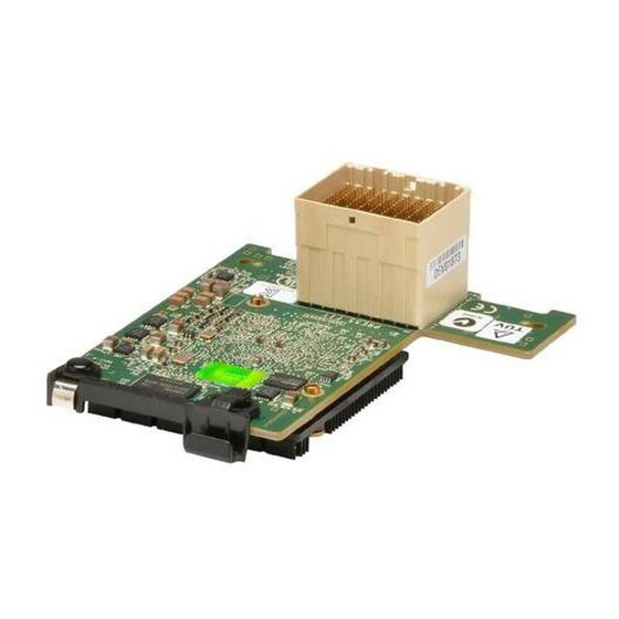
- Page 1 User’s Guide Converged Network Adapter QME8242 Third party information brought to CU0354602-00 A you courtesy of Dell.
-
Page 2: Document Revision History
User’s Guide Converged Network Adapter Information furnished in this manual is believed to be accurate and reliable. However, QLogic Corporation assumes no responsibility for its use, nor for any infringements of patents or other rights of third parties which may result from its use. -
Page 3: Table Of Contents
Table of Contents Introduction Overview ........... User’s Guide Content . - Page 4 User’s Guide Converged Network Adapter Installation Overview ........Installing Windows Drivers and Applications Using the InstallShield Wizard .
- Page 5 User’s Guide Converged Network Adapter Installing the ESX iSCSI Driver ......2-27 Installing the Driver for Devices as Part of a New ESX Installation (ESX Only) .
- Page 6 User’s Guide Converged Network Adapter Enabling CHAP Authentication with QConvergeConsole ..3-20 Configuring CHAP with QConvergeConsole CLI ... . 3-20 Linking to a CHAP Target ......3-23 General Management with NIC Partitioning .
- Page 7 User’s Guide Converged Network Adapter User Diagnostics for VMware NIC Driver Management Applications..........3-64 Ethtool .
- Page 8 User’s Guide Converged Network Adapter Setting Up iBFT on IPv6 ........4-25 Setting Up a Static IPv6 Address .
- Page 9 3-52 QLogic QME8242 CNA Function Configuration......Dell BIOS: Boot Settings ..........
- Page 10 User’s Guide Converged Network Adapter Running Windows Diagnostic Tests in the CLI......3-56 Windows Diagnostic Test Messages .
-
Page 11: Introduction
This guide provides technical information to system administrators for the QLogic QME8242 mezzanine card, including how to install, configure, and use the products and their functions. User’s Guide Content The QLogic QME8242 Mezzanine Card User’s Guide includes the following sections Hardware Installation covers the hardware and software requirements, ... -
Page 12: Features
Introduction Functionality and Features Features The QME8242 adapter provides the following features: NIC Partitioning (NPAR) Message Signaled Interrupts (MSI-X) Device management for power and SAN Multi-boot capability including: Preboot-eXecution Environment (PXE) iSCSI Fibre Channel ... -
Page 13: Supported Operating Systems
Introduction Functionality and Features Advanced management features for iSCSI and Fibre Channel adapters, including QConvergeConsole (GUI and CLI) Interrupt management and scalability features including: Receive Side Scaling (RSS) Interrupt moderation Flow control Locally Administered Address (LAA) Enhanced optimization with MSI, MSI-X, and NetQueue ... -
Page 14: Documentation Conventions
Introduction Documentation Conventions Documentation Conventions This guide uses the following documentation conventions: NOTE: provides additional information. CAUTION! indicates the presence of a hazard that has the potential of causing damage to data or equipment. WARNING!! indicates the presence of a hazard that has the potential of causing personal injury. -
Page 15: Regulatory Information
Introduction Regulatory Information Regulatory Information UL and CUL Listing This information technology equipment is UL-Listed and CUL-Listed for use with UL-Listed personal computers that have installation instructions detailing user installation of card cage accessories. CAUTION! Power off the computer and all attached devices such as monitors, printers, and external components. -
Page 16: Canadian Compliance (Industry Canada)
Introduction Regulatory Information Connect the equipment into an outlet on a circuit different from that to which the receiver is connected. Consult the dealer or an experienced radio/TV technician for help. NOTE: This device complies with Part 15 of the FCC Rules. Operation is subject to the following two conditions: (1) This device may not cause harmful interference, and (2) this device must accept any interference received, including interference that may cause undesired operation. -
Page 17: Hardware Installation
Hardware: For port and slot assignments, refer to the blade and M1000e chassis diagram in the Dell PowerEdge M1000e Systems Configuration Guide for the blade and chassis. Software: For information on the supported operating systems, firmware versions, adapter drivers, and utilities, refer to the product release notes. -
Page 18: Pre-Installation Checklist
1-1. Verify that your system is using the latest BIOS. NOTE: If you acquired the adapter software on a disk or from the Dell support website (http://support.dell.com), verify the path to the adapter driver files. Check the adapter for visible signs of damage. Never attempt to install a damaged adapter. -
Page 19: Driver Installation And Configuration
Driver Installation and Configuration Overview This section provides links to the following information about the three drivers—NIC, iSCSI, and FCoE—included with the QLogic QME8242: Windows Driver Installation and Configuration Linux Driver Installation and Configuration VMware Driver Installation and Configuration... -
Page 20: Windows Driver Installation And Configuration
(CLI), as summarized in the following sections. Installing Windows Drivers and Applications Using the InstallShield Wizard To download and run the QLogic P3P Installer (DELL) - InstallShield Wizard: From the Dell web site, locate and save the QLogic_1.0_Windows_A00.exe self-extracting zip file to your local drive. -
Page 21: Windows Driver Installation Files
2–Driver Installation and Configuration Windows Driver Installation and Configuration The drivers are extracted to the following folder (for example): C:\Temp\Download\Setup Select the appropriate driver for the device and OS, as shown in Table 2-1. Install the drivers following specific procedures for the NIC, iSCSI, and FCoE drivers. - Page 22 2–Driver Installation and Configuration Windows Driver Installation and Configuration Table 2-1. Windows Driver Installation Files (Continued) Windows OS Path and File Name Description Version zipQLogic 8100 and 8200 Windows 2003 <download folder>\x64\Win2003R2\ Series FCoE Driver R2 x64 qfcoewx64Stor QLogic 4000 and 8200 Windows 2003 <download folder>\x64\Win2003R2\ Series iSCSI Driver...
-
Page 23: Installing The Windows Nic Driver
2–Driver Installation and Configuration Windows Driver Installation and Configuration Installing the Windows NIC Driver After you extract the files from the archive, you can use them to do a Plug and Play update or an installation. For example: Start Windows Device Manager. Right-click the NIC you want to update, and then select Update Driver. - Page 24 2–Driver Installation and Configuration Windows Driver Installation and Configuration This procedure requires a system with a floppy drive. Before you begin, extract the drivers from the SuperInstaller (see “Extracting and Installing Windows Drivers Manually” on page 2-2). To initially install Windows on the boot from SAN disk attached to the QLogic iSCSI Adapter: Start the Windows installation procedure using the setup CD.
-
Page 25: Adding The Iscsi Adapter To The Existing Os
2–Driver Installation and Configuration Windows Driver Installation and Configuration Adding the iSCSI Adapter to the Existing OS To add the iSCSI Adapter driver to an existing Windows system, follow the appropriate procedure for your Windows platform. Windows 2003 This procedure requires extracting the driver to a folder on the hard drive and configuring it with the latest service pack and Windows updates. -
Page 26: Updating The Existing Driver
2–Driver Installation and Configuration Windows Driver Installation and Configuration When your computer comes up, Windows detects the newly-installed device and displays the message Found New Hardware with Ethernet Controller. The Found New Hardware wizard program starts installing a device driver for the newly-installed adapter. Click I don't have the disc. -
Page 27: Installing The Windows Fcoe Driver
2–Driver Installation and Configuration Windows Driver Installation and Configuration When the Select a Device Driver dialog box opens, click Next. On the Hardware Update Wizard: Completing the Hardware Update Wizard, click Finish. Windows Server 2008 If the driver is already installed and you want to install an updated version of the driver, follow these steps: Start the Device Manager as follows: Click Start, and then click Control Panel. - Page 28 2–Driver Installation and Configuration Windows Driver Installation and Configuration Windows Server 2003 NOTE: You must apply the Microsoft Storport update before installing or upgrading the driver. Windows Server 2003 SP2 (or later) requires Microsoft fixes KB932755 and KB939315 (or later). Windows Server 2003 SP1 requires Microsoft fixes KB932755 and KB939315 (or later).
-
Page 29: Adding The Converged Network Adapter To The Existing Os
2–Driver Installation and Configuration Windows Driver Installation and Configuration At the Load Driver window, insert the USB flash drive in a USB port, and then click OK. To continue with the standard installation procedure, click Next. Adding the Converged Network Adapter to the Existing OS To add the QME8242 Converged Network Adapter driver to an existing Windows system, follow the procedure provided for your Windows version. -
Page 30: Updating The Existing Driver
2–Driver Installation and Configuration Windows Driver Installation and Configuration Windows Server 2008 Connect the Converged Network Adapter to the appropriate slot on your computer according to the device manufacturer’s instructions. Restart or turn on the computer. Updating the Existing Driver To install an updated version of the driver, follow the procedure provided for your Windows version. -
Page 31: Linux Driver Installation And Configuration
2–Driver Installation and Configuration Linux Driver Installation and Configuration Linux Driver Installation and Configuration Installation Overview To install and configure the QME8242 drivers on a Linux system, refer to the driver release notes and readme files included in the package. NOTE: To install the Red Hat Package Manager (RPM), issue the following command as a root user:... -
Page 32: Building The Iscsi Adapter Driver For Rhel 5.4 And Rhel 5.5
2–Driver Installation and Configuration Linux Driver Installation and Configuration Building the iSCSI Adapter Driver for RHEL 5.4 and RHEL 5.5 Building and Installing the Adapter Driver Go to the directory that contains the driver package file qla4xxx-src-x.xx.xx.xx.xx.xx-k.tar.gz. Issue the following commands: # tar -xzvf qla4xxx-vx.xx.xx.xx.xx.xx-kx.tar.gz # cd qla4xxx-vx-x.xx.xx.xx.xx.xx-kx # tar -xvzf qla4xxx-src-vxx.xx.xx.xx.xx-ky.tar.gz... - Page 33 2–Driver Installation and Configuration Linux Driver Installation and Configuration Manually Loading the Adapter Driver Load the driver using one of the following methods: To directly load the driver from the local build directory, issue the following commands: # insmod /lib/modules/2.6.../kernel/drivers/scsi/scsi_transport_is csi2.ko # insmod qla4xxx.ko...
-
Page 34: Building The Iscsi Adapter Driver For Sles 10 Sp3 And Sles 11
2–Driver Installation and Configuration Linux Driver Installation and Configuration To create a backup copy of the RAM disk image, issue the following commands: # cd /boot # cp initrd-[kernel version].img initrd-[kernel version].img.bak Rebuild the initrd image by issuing the following commands: # mkinitrd -f initrd-[kernel version].img `uname -r` Reboot to boot from the new initrd image and new driver. - Page 35 2–Driver Installation and Configuration Linux Driver Installation and Configuration To build the iSCSI IOCTL Driver for SLES 10 SP3 and SLES 11, issue the following commands: # tar xvzf qisioctl-src-vx.xx.xx-dx.tar.gz # cd qisioctl-src-vx.xx.xx-dx # ./build.sh install Manually Loading the Adapter Driver To load the driver, use one of the following methods: To load the driver directly from the local build directories, issue the ...
-
Page 36: Building The Iscsi Adapter Driver For Rhel 6.0 And Sles 11 Sp1
2–Driver Installation and Configuration Linux Driver Installation and Configuration NOTE: For SLES 11, edit the /etc/modprobe.d/unsupported_modules file to make the following change: (replace allow_unsupported_modules 1 To create a backup copy of the RAM disk image, issue the following commands: # cd /boot # cp initrd-[kernel version].img initrd-[kernel version].img.bak Rebuild the initrd image by issuing the following commands:... - Page 37 2–Driver Installation and Configuration Linux Driver Installation and Configuration Manually Loading the Adapter Driver To load the driver, use one of the following methods: To load the driver directly from the local build directories, issue the following commands: # insmod /lib/modules/2.6.../kernel/drivers/scsi/ scsi_transport_iscsi.ko # insmod /lib/modules/2.6.../updates/qla4xxx.ko ...
-
Page 38: Installing The Linux Fcoe Driver
2–Driver Installation and Configuration Linux Driver Installation and Configuration Rebuild the initrd image with driver by issuing the following command: # mkinitrd -f initramfs-[kernel version].img `uname -r` Reboot the host to boot from the new initrd image with new driver. NOTE: Depending on the server hardware, the RAMDISK file name may be different. -
Page 39: Building The Driver For Rhel 6.0 Linux
2–Driver Installation and Configuration Linux Driver Installation and Configuration Automatically load the driver by rebuilding the RAM disk to include the driver as follows: Edit the /etc/modprobe.conf file and add the following entry (if it is not present): alias scsi_hostadapterX qla2xxx where, X is based on the order of the SCSI modules being loaded. -
Page 40: Building The Driver For Sles 10 Sp3 Linux
2–Driver Installation and Configuration Linux Driver Installation and Configuration Automatically load the driver by rebuilding the RAM disk to include the driver as follows: Edit the /etc/modprobe.conf file and add the following entry (if it is not present): alias scsi_hostadapterX qla2xxx where, X is based on the order of the SCSI modules being loaded. -
Page 41: Building The Driver For Sles 11 And Sles11 Sp1 Linux
2–Driver Installation and Configuration Linux Driver Installation and Configuration Manually load the driver for Linux. To load the driver using modprobe, issue the following command: # modprobe -v qla2xxx To unload the driver using modprobe, issue the following command: # modprobe -r qla2xxx Automatically load the driver by rebuilding the RAM disk to include the driver as follows:... - Page 42 2–Driver Installation and Configuration Linux Driver Installation and Configuration The build.sh script does the following: Builds the driver .ko files. Copies the .ko files to the appropriate /lib/modules/2.6.../updates directory. Adds the appropriate directive in the modprobe.conf file (if applicable).
-
Page 43: Vmware Driver Installation And Configuration
2–Driver Installation and Configuration VMware Driver Installation and Configuration VMware Driver Installation and Configuration Installation Overview To install and configure the QME8242 drivers on a VMware system, refer to the driver release notes and readme files included in the package. Installing the ESX NIC Driver The operating system manages and controls the driver installation process. -
Page 44: Updating An Existing Driver Or Installing A New Driver For An Existing Esx Installation With Esxupdate (Esx Only)
2–Driver Installation and Configuration VMware Driver Installation and Configuration Select driver module to import drivers to the ESX host. Click Next to continue. A dialog box displays the following message: Load the system drivers. Click Yes. After loading the driver module, continue installing ESX. After the drivers are installed, you are prompted to swap the driver CD with the ESX installation DVD. -
Page 45: Verifying The Version Of The Installed Driver
2–Driver Installation and Configuration VMware Driver Installation and Configuration Verifying the Version of the Installed Driver Power on the ESX or ESXi host. Verify the installed package in the system by issuing the following command: esxupdate query --vib-view | grep -i <driver-version / package-name>... -
Page 46: Installation (Esx Only)
2–Driver Installation and Configuration VMware Driver Installation and Configuration Place the driver CD in the DVD drive of the ESX host. Select the driver module to import drivers to the ESX host. To continue, click Next. On the Load the system drivers? message box, click Yes. After loading the driver module, continue installing ESX. -
Page 47: Verifying The Version Of The Installed Driver
2–Driver Installation and Configuration VMware Driver Installation and Configuration Verifying the Version of the Installed Driver Power on the ESX or ESXi host. Verify the installed package in the system by issuing the following command: esxupdate query --vib-view | grep -i <driver-version / package-name>... -
Page 48: Installation (Esx Only)
2–Driver Installation and Configuration VMware Driver Installation and Configuration To eject the ESX installation DVD, click Add. Place the driver CD in the ESX host DVD drive. Select the driver module from which to import drivers to the ESX host, and then click Next. -
Page 49: Verifying The Version Of The Installed Driver
2–Driver Installation and Configuration VMware Driver Installation and Configuration Verifying the Version of the Installed Driver Power on the ESX or ESXi host. Verify the installed package in the system by issuing the following command: esxupdate query --vib-view | grep -i <driver-version / package-name>... -
Page 50: Introduction
2–Driver Installation and Configuration VMware Driver Installation and Configuration Introduction The QLogic Adapter vCenter Plug-in is a user-interface extension to the vSphere Client that allows you to manage and configure QLogic adapters, including the NIC Partitioning feature (“NIC Partitioning (NPAR)” on page 3-25), on ESX and ESXi servers. -
Page 51: Requirements
2–Driver Installation and Configuration VMware Driver Installation and Configuration Requirements The QLogic Adapter vCenter Plug-in requires the following to be installed and running, as shown in the Figure 2-2. Figure 2-2. vCenter Plug-in Requirements QLogic provides the following components that must be installed on the ESX or ESXi Server, vCenter Server, and Tomcat Web Server. - Page 52 2–Driver Installation and Configuration VMware Driver Installation and Configuration This section provides the following installation procedures for the CIM Provider: Initial Installation Subsequent Update Installation Initial Installation To install the QLogic Adapter CIM Provider using the esxupdate command (ESX systems only): Copy the offline-bundle.zip file into the root directory (/) of the ESX system.
-
Page 53: Starting The Qlogic Adapter Cim Provider
2–Driver Installation and Configuration VMware Driver Installation and Configuration Subsequent Update Installation To update the QLogic Adapter CIM Provider after a prior VIB installation: Follow the instructions in “Removing the QLogic Adapter CIM Provider” on page 2-35 to remove the existing VIB. Follow the instructions in “Initial Installation”... -
Page 54: Installing The Qlogic Adapter Vcenter Plug-In
2–Driver Installation and Configuration VMware Driver Installation and Configuration Remove the existing VIB as follows: # esxupdate remove -b <vibID> To uninstall from a remote host using the vihostupdate command: NOTE: To uninstall the provider from a remote host using the vihostupdate command, make sure that the ESX/ESXi system is in Maintenance Mode. -
Page 55: Starting The Qlogic Adapter Vcenter Plug-In
2–Driver Installation and Configuration VMware Driver Installation and Configuration Starting the QLogic Adapter vCenter Plug-in To start the QLogic Adapter vCenter Plug-in: Start the VMware vSphere Client and connect to the vCenter Server by entering the IP address or name, user name, and password, and then clicking the Login button. -
Page 56: Updating The Flash
2–Driver Installation and Configuration VMware Driver Installation and Configuration If it does not already exist, edit and append the /usr/lib/vmware/bin/qlflash entry in the /etc/vmware/UserWorldBinaries.txt file. To install the qlflash utility on ESXi: For ESXi, the qlflash utility is not required, so no additional steps are necessary. -
Page 57: Using The Vcenter Plug-In On A Tomcat Server
2–Driver Installation and Configuration VMware Driver Installation and Configuration In the Flash update successful completion message box, click OK. If you clicked OK in Step 7, you can click Refresh to verify the new firmware version. Otherwise, you must reboot the system for the new firmware to take effect. - Page 58 2–Driver Installation and Configuration VMware Driver Installation and Configuration Starting and Stopping Tomcat on Linux To start Tomcat, issue the following command: # $CATALINA_HOME/bin/startup.sh To stop Tomcat, issue the following command: # $CATALINA_HOME/bin/shutdown.sh Installing Tomcat on Windows Go to either of the following URLs: http://tomcat.apache.org/download-60.cgi http://tomcat.apache.org/download-70.cgi Locate the following directory and file:...
-
Page 59: Plug-In Unregistration From A Manual Install
2–Driver Installation and Configuration VMware Driver Installation and Configuration On the User Input window, type your vCenter Server IP address, username, and password, as well as the IP address of your local Tomcat server. Then click Next to continue. On the Please Wait window, wait while the QLogic Adapter vCenter Plug-in is configured for your system and registers the plug-in with the vCenter Server. -
Page 60: Launching The Plug-In From Vsphere Client
2–Driver Installation and Configuration VMware Driver Installation and Configuration Launching the Plug-in from vSphere Client Start the vSphere Client and connect to the vCenter Server. (If you start and connect the vSphere Client directly to an ESX or ESXi server, the vCenter plug-in does not appear.) If you have not already done so, create a data center and add the ESX server. -
Page 61: Adapter Management Applications
Adapter Management Applications This chapter describes the following adapter management applications: General Management with QConvergeConsole General Management with NIC Partitioning Windows Management Applications Linux Management Applications VMware Management Applications CU0354602-00 A... -
Page 62: General Management With Qconvergeconsole
3–Adapter Management Applications General Management with QConvergeConsole General Management with QConvergeConsole Use the QConvergeConsole utility to manage the QME8242 as follows: Configuring iSCSI Offload with QConvergeConsole Configuring iSCSI Initiators with QConvergeConsole Enabling CHAP Authentication with QConvergeConsole Configuring iSCSI Offload with QConvergeConsole The iSCSI offload feature provides full iSCSI offloads that include header and data digest, receive Protocol Data Unit (PDU) parsing, and direct data placement. - Page 63 3–Adapter Management Applications General Management with QConvergeConsole Displaying Adapter-Level iSCSI Parameters To view the adapter configured settings, issue the -ch command. The positional parameter, [hba_port_inst], is optional. If an hba_port_inst is specified, information for only that adapter is shown. If the hba_port_inst is not specified, information for all adapters in the system is listed.
- Page 64 3–Adapter Management Applications General Management with QConvergeConsole Port-Level iSCSI Parameters This section shows the commands used to display and to modify port-level iSCSI parameters. Displaying Port-Level iSCSI Parameters Use the -c command to view port configured settings. The positional parameter, [hba_port_inst], is optional.
- Page 65 3–Adapter Management Applications General Management with QConvergeConsole iSCSI_Data_Seq_In_Order on(*) iSCSI_Data_PDU_In_Order on(*) iSCSI_CHAP_Auth off(*) iSCSI_Bidi_CHAP_Auth off(*) iSCSI_Snack iSCSI_Discovery_Logout iSCSI_Strict_Login iSCSI_Error_Recovery_Level 0(*) iSCSI_Alias *** Displaying Firmware Settings inst=0 *** FW_Marker on(*) FW_Stat_Alarm off(*) FW_Accept_AEN off(*) FW_Access_Control off(*) FW_Session_Mode on(*) FW_Initiator_Mode on(*) FW_Target_Mode off(*) FW_Fast_Posting off(*)
- Page 66 3–Adapter Management Applications General Management with QConvergeConsole ENABLE_IPV4 ENABLE_IPV6 LOC_LINK_AUTO ROUTABLE_AUTO LDROUTER_AUTO IPv6_Addr_Local_link fe80:: ENABLE_4022IPV4 *** Displaying Advanced Settings inst=0 *** FW_Marker on(*) FW_Stat_Alarm off(*) FW_Accept_AEN off(*) FW_Access_Control off(*) FW_Session_Mode on(*) FW_Initiator_Mode on(*) FW_Target_Mode off(*) FW_Fast_Posting off(*) FW_Sense_Buffer_Desc off(*) FW_ZIO_Enable_Mode AFW_Device_Timeouts AFW_Delayed_Ack AFW_AutoConnect...
- Page 67 3–Adapter Management Applications General Management with QConvergeConsole TCP_Time_Stamp TCP_Window_Scale iSCSI_Name iqn.2000-04.com.qlogic:isp8214.000e1e031685.5 IPv4TOS IPv4TTL IPV6_TCP_Timer_Scale 3(*) IPv6_TCP_Time_Stamp IPv6_TCP_Window_Scale IPv6_VLAN_ID IPv6_VLAN_User_Priority IPv6_VLAN_Enable IPv6_Traffic_Class IPv6_Hop_Limit IPv6_ND_Reachable_Timer IPv6_ND_Retransmit_Timer IPv6_ND_Stale_Timeout IPv6_DAD_Count IPv6_Router_Advertised_MTU 0(*) IPv4_Address_State Valid(*) IPv6_Link_Loc_Address_State Invalid(*) IPv6_Address0_State Invalid(*) IPv6_Address1_State Invalid(*) IPv6_Default_Router_State No router(*) IPv6_MCast_Listnr_Disco_Enable ACB_Version 2(*) AFW_Serlz_Task_Mngmt...
- Page 68 3–Adapter Management Applications General Management with QConvergeConsole Modifying Port-Level iSCSI Parameters Use the –n command to modify port-level iSCSI parameters. Command line options: -n <hba_port_inst> <config_name|config_alias> <value> <config_name|config_alias> <value> Example: In the following example, the HBA port instance = 0 and the parameter change is to turn on iSCSI header digests.
- Page 69 3–Adapter Management Applications General Management with QConvergeConsole VLAN_ID VLANID 0 to 4095 IP_Address IPAD IPv4 address format IP_Subnet_Mask IPSM IPv4 address format IP_Gateway IPGW IPv4 address format 2 to 16 FW_ZIO_Enable_Mode ZIOE on or off Task_Management_Timeout TMTO 0 to 65535 ENABLE_IPV4 EIPV4 on or off...
- Page 70 3–Adapter Management Applications General Management with QConvergeConsole Summary of Target Sessions Use the -ts command to display summary information for both persistent and non-persistent targets. Both [hba_port_inst] and [target_id] are optional parameters. If neither of the parameters is present, the information is displayed for all adapters and all targets.
- Page 71 3–Adapter Management Applications General Management with QConvergeConsole Target Session-Level iSCSI Negotiated Parameters Use the -t command to display information for targets. The positional parameter is <hba_port_inst>. The optional parameter is [target_id]. If only the hba_port_inst is entered, target information for all targets on the specified adapter is displayed.
- Page 72 3–Adapter Management Applications General Management with QConvergeConsole TGTISCSIO_Discovery_Logout TGTISCSIO_Strict_Login TGTISCSIO_Error_Recovery_Level 0(*) TGT_KeepAliveTimeout TGT_DefaultTimeout TGT_DefaultTime2Retain 20(*) TGT_MaxBurstLen TGT_MaxOutstandingR2T TGT_MaxRxDataSegmentLen 128(*) TGT_MaxTxDataSegmentLen 0(*) TGT_Port 3260 TGTTCPO_Nagle TGTTCPO_Timer_Scale 0(*) TGTTCPO_Timestamp TGT_TaskManagementTimeout TGT_ExeCount 0(*) TGT_TargetPortalGroupID 1(*) TGT_InitiatorSessID 0x000e1e031685 TGT_TargetSessID 9(*) TGT_TargetIPAddress 192.168.105.247 TGT_Window_Scale_Enable TGT_Rx_Window_Scale TGT_Tx_Window_Scale 0(*) TGT_TimeStamp_Enable...
- Page 73 3–Adapter Management Applications General Management with QConvergeConsole Target Session-Level Persistent iSCSI Parameters This section shows the commands used to display and to modify target session-level persistent iSCSI parameters. Displaying Target Session-Level Persistent iSCSI Parameters Use the -tp command to view target persistent parameter information (pre-negotiation, from Flash).
- Page 74 3–Adapter Management Applications General Management with QConvergeConsole TGTISCSIO_Data_PDU_In_Order on(*) TGTISCSIO_CHAP_Authentication TGTISCSIO_Bidi_CHAP_Authentication TGTISCSIO_Snack TGTISCSIO_Discovery_Logout TGTISCSIO_Strict_Login TGTISCSIO_Error_Recovery_Level 0(*) TGT_KeepAliveTimeout TGT_DefaultTimeout TGT_DefaultTime2Retain 20(*) TGT_MaxBurstLen TGT_MaxOutstandingR2T TGT_MaxRxDataSegmentLen 128(*) TGT_MaxTxDataSegmentLen 0(*) TGT_Port 3260 TGTTCPO_Nagle TGTTCPO_Timer_Scale 0(*) TGTTCPO_Timestamp TGT_TaskManagementTimeout TGT_ExeCount 0(*) TGT_TargetPortalGroupID 1(*) TGT_InitiatorSessID 0x000e1e031685 TGT_TargetSessID 9(*) TGT_TargetIPAddress 192.168.105.247...
- Page 75 3–Adapter Management Applications General Management with QConvergeConsole Modifying Target Session-Level iSCSI Parameters Use the –tc command to modify target session-level iSCSI parameters. The positional parameters are <hba_port_inst>, <target_id>, and a series of one or more parameter name-value pairs. Command line options: -tc <hba_port_inst>...
-
Page 76: Configuring Iscsi Initiators With Qconvergeconsole
3–Adapter Management Applications General Management with QConvergeConsole address format TGT_IPv6_iSCSIName TGTINAME_IPv6 Character string TGT_IPv6_Port TGTPORT_IPv6 0 to 32767 TGT_DIF_Enable TGTDIFEN_IPv6 on or off TGT_Max_Segment_Size TGTMSS 0 to 65535 TGT_IPv6_Source_Addr_Flg TGTSRCADDR_IPv6 0 to 3 (0=Don't Care, 1=Link Local, 2=Address 0, 3=Address 1) TGT_IPv6_Flow_Label TGTFLWLBL 0x0 to 0xfffff... - Page 77 3–Adapter Management Applications General Management with QConvergeConsole On the Converged Network Adapter (CNA) Protocol Type Selection menu, select 1, CNA iSCSI Configuration. On the Converged Network Adapter (CNA) iSCSI Configuration menu, select 3, Port IP Settings. Select the Converged Network Port you want to configure. Select 2, Configure IP Settings.
-
Page 78: Configuring The Linux Iscsi Initiator
3–Adapter Management Applications General Management with QConvergeConsole Configuring the Linux iSCSI Initiator Use the QConvergeConsole CLI to configure the iSCSI initiator for Linux. To configure a Linux iSCSI initiator: Access the QConvergeConsole CLI by entering qaucli in a terminal window. On the QConvergeConsole CLI Main Menu, select 2, Adapter Configuration. -
Page 79: Configuring The Esx Iscsi Initiator
3–Adapter Management Applications General Management with QConvergeConsole Complete the interactive list of settings as follows: IPv6 Target? [off]: Press ENTER to accept the default. TGT_iSCSI_Name [ ]: Type the iSCSI Qualified Name (IQN) of the iSCSI target to connect to, and then press ENTER. TGT_Port [3260]: Press ENTER to accept the default. -
Page 80: Enabling Chap Authentication With Qconvergeconsole
3–Adapter Management Applications General Management with QConvergeConsole Enabling CHAP Authentication with QConvergeConsole You can enable CHAP authentication with either the interactive mode or non-interactive mode of QConvergeConsole CLI. For details on the interactive mode, refer to the QConvergeConsole CLI User’s Guide. For the non-interactive mode of the QConvergeConsole CLI, the following sections describes how to enable CHAP: ... - Page 81 3–Adapter Management Applications General Management with QConvergeConsole To add a peer and BIDI CHAP entry (name and secret), issue the -addchap command to add a CHAP entry to the persistent CHAP table. The positional parameters are <hba_port_inst>, <CHAP name>, and <CHAP secret>. The optional parameter is [-BIDI] indicating the CHAP entry is a BIDI entry (default is local CHAP).
- Page 82 3–Adapter Management Applications General Management with QConvergeConsole Command line options: -pa <hba_port_inst> <ip address> [-PORT port_num] [-INAME name] Example: In the following examples, the HBA port instance = 0 and the Send Target IP = 10.14.64.154. $qaucli -pr iscsi -pa 0 10.14.64.154 $qaucli -iscsi -pa 0 10.14.64.154 To display a persistent Send Target entry, issue the -ps command (you should initially expect a failed connection because the target is not yet linked...
-
Page 83: Linking To A Chap Target
3–Adapter Management Applications General Management with QConvergeConsole Example: In the following examples, the HBA port instance = 0, the CHAP number = 1, and the Target ID = 2. $qaucli -pr iscsi -linkchap 0 1 2 $qaucli -iscsi -linkchap 0 1 2 Linking to a CHAP Target You can link CHAP to a target with active bidirectional (BIDI) CHAP authentication. - Page 84 3–Adapter Management Applications General Management with QConvergeConsole To view all targets linked to the CHAP, issue the -chapmap command. This command lists the mapping of targets to CHAP table entries. The positional parameter for this command is <hba_port_inst>. Command line options: -chapmap <hba_port_inst>...
-
Page 85: General Management With Nic Partitioning
3–Adapter Management Applications General Management with NIC Partitioning General Management with NIC Partitioning Use the NIC Partitioning (NPAR) feature to manage the QME8242 as described in the following section. NIC Partitioning (NPAR) This section provides the following information about the QLogic NIC Partitioning (NPAR) feature: ... -
Page 86: Windows Management Applications
3–Adapter Management Applications Windows Management Applications Perform NPAR configuration using any of the following methods: OptROM Lifecycle controller Managements tools under various operating systems After you have configured NPAR mode, you can modify the minimum and maximum bandwidth per NPAR. The changes take effect immediately; no reboot is required. - Page 87 3–Adapter Management Applications Windows Management Applications Viewing Adapter Properties Issue the following commands to view the adapter properties. To list all detected QME8242 ports: qaucli -nic -i [cna_port_inst] To view QME8242 information: qaucli -nic -icna [cna_port_inst] To view port Data Center Bridging Exchange (DCBX) protocol information: qaucli -nic -idcbx [cna_port_inst] To view configured port settings: qaucli -nic -iset [cna_port_inst]...
-
Page 88: Windows Teaming
VLAN_ID 1..4094 To set the QME8242 configuration alias, issue the following command: qaucli -nic -nh [cna_port_inst] <config_name|config_alias> <value> [<config_name|config_alias> <value>] Windows Teaming Windows Teaming: QLogic QME8242 Mezzanine Card User’s Guide Overview Teaming Modes Using the CLI for Teaming ... - Page 89 3–Adapter Management Applications Windows Management Applications Overview You can group together multiple network adapters in a server to make a team. Individual adapters that are part of a team operate as a team rather than standalone adapters. A team provides traffic load balancing across the member adapters and fault tolerance when some, but not all, of the members lose connectivity.
-
Page 90: Windows Teaming Modes
3–Adapter Management Applications Windows Management Applications Table 3-2. Windows Teaming Modes Number of Ports per Failover Switch Load Mode (System Fault Team Capability Dependency Balancing Tolerance) (Range Failsafe Yes: Layer 2 No 2-16 Tx load balancing Yes: Layers 3 or 4 2-16 Static 802.3ad 2-16 Dynamic 802.3ad... - Page 91 3–Adapter Management Applications Windows Management Applications Switch-Independent Load Balancing Mode Switch-independent load balancing mode provides a failsafe feature and supports transmit load balancing. For receive load balancing, use the 802.3ad modes. In this mode, the outbound traffic is efficiently distributed across the member adapters to increase the transmit bandwidth.
- Page 92 3–Adapter Management Applications Windows Management Applications Static Link Aggregation (SLA) Static Link Aggregation (SLA, 802.3ad static protocols with generic trunking) is a switch-assisted teaming mode, where the switch must be 802.3ad compliant. The switch ports must be configured so that the switch perceives adapters from a LAG as a single, virtual adapter.
-
Page 93: Using The Cli For Teaming
3–Adapter Management Applications Windows Management Applications Using the CLI for Teaming You can view, create, configure, and delete teams using the QConvergeConsole utility. To view a list of teams, issue the following command: qaucli -nic –teamlist To view team information, issue the following command: qaucli -nic -teaminfo <team_inst|ALL>... -
Page 94: Teaming Configuration
3–Adapter Management Applications Windows Management Applications Figure 3-1. Team Management Property Page On the Team Management page, the Teams and Adapters pane on the left lists the network devices currently present on this system, including: Teams and virtual adapters, as well as their member physical adapters ... -
Page 95: Creating A Team
3–Adapter Management Applications Windows Management Applications Creating a Team To create a team: Right-click the Teams folder icon, and then click Create Team (see Figure 3-2). Figure 3-2. Creating a Team The software automatically picks a unique team name, or you may choose to enter your own team name. - Page 96 3–Adapter Management Applications Windows Management Applications Active LACP: LACP is a Layer 2 protocol that is used control the teaming of physical ports into an aggregated set. LACP discovers if a host’s ports are connected to a switch that supports aggregation on the connected ports and configures those ports into an aggregation bundle.
-
Page 97: Creating A Failsafe Team
3–Adapter Management Applications Windows Management Applications Figure 3-3. Creating a Failsafe Team Figure 3-4. Creating a Switch-Independent Load Balancing Team CU0354602-00 A 3-37... -
Page 98: Creating An 802.3Ad Static Team
3–Adapter Management Applications Windows Management Applications Figure 3-5. Creating an 802.3ad Static Team Figure 3-6. Creating an 802.3ad Dynamic Team 3-38 CU0354602-00 A... -
Page 99: Setting Advanced Team Properties
3–Adapter Management Applications Windows Management Applications Figure 3-7. Setting Advanced Team Properties To confirm if a team has been successfully created, view the Team and Adapters pane on the Team Management page. Figure 3-8 shows an example of a newly-formed team. The Team Data pane on the right shows the properties, information, and status of the team or adapter that is currently selected in the Teams and Adapters pane on the left. -
Page 100: Adding A Team
3–Adapter Management Applications Windows Management Applications Modifying a Team A team can be modified by: Adding or removing one or more team members to a team. Modifying the team properties. To add team members: On the Team Management property page, right-click the unteamed adapter to add to a team. -
Page 101: Modifying Advanced Team Properties
3–Adapter Management Applications Windows Management Applications To remove an adapter from a team: NOTE: A team must include at least one QLogic adapter. A QLogic adapter is allowed to be deleted from a team only if it is not the last QLogic teamed adapter. -
Page 102: Modifying Team Properties
3–Adapter Management Applications Windows Management Applications NOTE: To ensure that the properties of all teamed adapters and adapters with VLANs remain synchronized with the team properties, do not directly modify the adapter properties on the Advanced page. If an adapter property becomes out of sync with its team properties, change either the team or adapter property so that they are the same on each, and then reload the team. -
Page 103: Modifying Failsafe Team Properties
3–Adapter Management Applications Windows Management Applications Example 1: For a failsafe team, you can change the team name, assigned team static MAC address, preferred primary adapter, and failback type, as shown in Figure 3-12. Figure 3-12. Modifying Failsafe Team Properties Example 2: You can change the team type and the corresponding team attributes. -
Page 104: Viewing Teaming Statistics
3–Adapter Management Applications Windows Management Applications Deleting a Team To delete a team: On the Team Management property page, in the left pane under Teams and Adapters, right-click the team name to be deleted. On the shortcut menu, click Delete team. Saving and Restoring Teaming Configuration It is recommended that you periodically save the configuration to prevent any accidental loss of network topology and settings. -
Page 105: Windows Vlan Configuration
3–Adapter Management Applications Windows Management Applications Windows VLAN Configuration The term VLAN (Virtual Local Area Network) refers to a collection of devices that communicate as if they were on the same physical LAN. VLAN information covered in this section includes the following: ... -
Page 106: Using The Gui For Vlans
3–Adapter Management Applications Windows Management Applications To preview a VLAN before removing it from a port or team, issue the following command to list the indices to use in the -vlandel command: qaucli -nic -vlandel_preview To remove a VLAN from a port or team, issue the following command: qaucli -nic -vlandel <list_insts|ALL>... -
Page 107: Adding A Vlan
3–Adapter Management Applications Windows Management Applications To add and configure a VLAN: On the Team Management page under Teams and Adapters, right-click either a team or an unteamed adapter. On the shortcut menu, click Add VLAN (see Figure 3-14). Figure 3-14. Adding a VLAN On the Configure VLAN dialog box (see Figure 3-15), type values in the... -
Page 108: Viewing Vlan Data Properties
3–Adapter Management Applications Windows Management Applications When the VLAN addition is complete, the added VLAN is visible as a Virtual Adapter on the Team Management page under Teams and Adapters. Click the added virtual adapter to view all the properties, information, and status of the virtual adapter in the VLAN Data pane (see Figure 3-16). -
Page 109: User Diagnostics For Windows Nic Driver Management Applications
3–Adapter Management Applications Windows Management Applications NOTE: To allow VLAN deletion, there must be at least one VLAN on the team. Deleting the last VLAN on the team results in deletion of the entire team. Viewing VLAN Statistics Follow these steps to view statistics for a selected VLAN. To view VLAN statistics: On the Team Management page, click a team name in the left pane under the Teams folder. -
Page 110: Diagnostics Tests On Windows
3–Adapter Management Applications Windows Management Applications To run user diagnostics in the GUI: Access the Windows Control Panel, and then open the Device Manager. In the Device Manager, right-click the QLogic 10 Gb Ethernet adapter, and then on the shortcut menu, click Properties. On the adapter properties page, click the Diagnostics tab. -
Page 111: Windows Qconvergeconsole Cli-Selecting A Protocol In Menu Mode
3–Adapter Management Applications Windows Management Applications To run user diagnostics in the CLI: Use QConvergeConsole CLI (qaucli), a unified command line utility, to manage all QLogic adapter models, including running user diagnostics. The overall option (-pr <protocol>) allows you to start the utility with a specific protocol type, either NIC, iSCSI, or Fibre Channel. -
Page 112: Windows Qconvergeconsole Cli-Getting Help
3–Adapter Management Applications Windows Management Applications Diagnostic help commands, and command options available for each specific protocol, are available by specifying -h to the protocol, as shown in Table 3-5. Table 3-5. Windows QConvergeConsole CLI—Getting Help Command Description Print usage of a specific adapter type, and then exit Print NIC protocol usage, and then exit qaucli -pr nic -h Print Fibre Channel and FCoE protocol usage, and then exit... - Page 113 3–Adapter Management Applications Windows Management Applications Table 3-7. Windows QConvergeConsole CLI—Diagnostic Test Commands (Continued) Command Description Internal loopback test (default) ---IntLB Hardware test (default) --Hw Link status test (default) --LinkST No control registers test (combine –D or –a) --noCRegs No interrupt test (combine –D or –a) --noIRQS No internal loopback test (combine –D or –a) --noIntLP...
-
Page 114: Windows Diagnostic Test Descriptions
3–Adapter Management Applications Windows Management Applications Table 3-8. Running Windows Diagnostic Tests in the CLI Test Type Command External qaucli -nic -extloopback <cna_port_inst> <tests_num> Loopback <on_error> where <tests_num> specifies the number of tests, 1–65535, and <on_error> is either 0=Ignore or 1=Abort. NOTE: This test requires a pass-through module to be configured for both ports. -
Page 115: Windows Diagnostic Test Messages
3–Adapter Management Applications Windows Management Applications Loopback Test The loopback test is a diagnostic tool that routes transmit data through a loopback connector back to the same adapter. Link Test The link test inspects the link status (up or down) by checking the physical communication channel between the host and the firmware. - Page 116 3–Adapter Management Applications Windows Management Applications Table 3-9. Windows Diagnostic Test Messages (Continued) Test Error Message Description Hardware HW_SRE_L1IPQ Segmentation and Reassembly Engine currently paused due to L1 IPQ discard failure Hardware HW_SRE_L2IPQ Segmentation and Reassembly Engine currently paused due to L2 IPQ discard failure Hardware HW_SRE_FREEBUF Segmentation and Reassembly Engine free buffer list is...
-
Page 117: Linux Management Applications
3–Adapter Management Applications Linux Management Applications For example: qaucli -nic -testlink === Link Test for 1. CNA Port Index === Function is not supported by this hardware/driver/api stack === Link Test for 2. CNA Port Index === Function is not supported by this hardware/driver/api stack === Link Test for 3. - Page 118 3–Adapter Management Applications Linux Management Applications qaucli Utility Install QConvergeConsole CLI (qaucli) from the following packages supplied by QLogic: Package file QConvergeConsoleCLI-<version>_linux_<arch>.install.tar.gz RPM installer package file QConvergeConsoleCLI-<version>_<arch>.rpm Example RPM package installation: To determine if the QCC is installed and to find the full name of the installed QCC RPM package, issue the following command using the partial name “QConvergeConsoleCLI”...
-
Page 119: Ethtool Utility
3–Adapter Management Applications Linux Management Applications ethtool Utility Use the ethtool utility to view adapter statistics and configure interface options. For additional details, refer to qlcnic driver man page and ethtool man page. Examples: To disable transmit segmentation offload, issue the following command, where [n] represents a numerical value for a specific instance: ethtool -K eth[n] tso off To list interface statistics, issue the following command, where [n] represents a... -
Page 120: User Diagnostics For Linux Nic Driver Management Applications
3–Adapter Management Applications Linux Management Applications Port: FIBRE PHYAD: 1 Transceiver: external Auto-negotiation: off Supports Wake-on: g Wake-on: g Current message level: 0x00000000 (0) Link detected: yes phantomcore Utility Use the phantomcore utility to collect a firmware dump that is useful for forwarding to QLogic Support. - Page 121 3–Adapter Management Applications Linux Management Applications QConvergeConsole Diagnostics NOTE: For an overview of the GUI version of QLogic’s QConvergeConsole utility, Appendix C. Information on installing and starting the utility’s GUI version is provided in the QConvergeConsole User's Guide. All procedural information for the utility is covered in the online help system.
-
Page 122: Linux Diagnostic Test Messages
3–Adapter Management Applications Linux Management Applications The self-test includes the following: Loopback test Interrupt test Link test Register test Examples: # ethtool -t eth8 offline The test result is PASS The test extra info: Register_Test_on_offline Link_Test_on_offline Interrupt_Test_offline Loopback_Test_offline # ethtool -t eth4... -
Page 123: Vmware Management Applications
3–Adapter Management Applications VMware Management Applications VMware Management Applications VMware management applications for the QME8242 include the following: VMware NIC Driver Management Applications User Diagnostics for VMware NIC Driver Management Applications VMware NIC Driver Management Applications This section provides the following information about the VMware NIC driver management applications. -
Page 124: User Diagnostics For Vmware Nic Driver Management Applications
3–Adapter Management Applications VMware Management Applications User Diagnostics for VMware NIC Driver Management Applications This section covers the following information for user diagnostics for VMware. Ethtool Use the ethtool utility to view adapter statistics and configure interface options. Supported options include the display of device information, protocol offload options, driver information, adapter statistics, and more. - Page 125 3–Adapter Management Applications VMware Management Applications UEFI Package Contents Files in the UEFI driver package include the following: p3pxxxxx.bin is a combined binary file, which includes the binaries for BIOS, FCode, UEFI driver, and RISC firmware. EfiUtil.EFI or EfiUtilx64.EFI is the UEFI Utility to update the UEFI driver, firmware, and NVRAM.
- Page 126 3–Adapter Management Applications VMware Management Applications The EfiUtilx64 is a QLogic Flash programming utility for UEFI. To run the utility, boot the UEFI shell. Do not run this utility from a drive connected to a Converged Network Adapter. Make sure update.nsh, efiutilx64.efi, ql8xxx.drv, and p3pxxxxx.bin source files are in the same directory.
-
Page 127: Boot Configuration
Boot Configuration This section provides the following information about boot configuration for the QLogic QME8242: Boot from SAN PXE Boot Setup iSCSI Configuration Using Fast!UTIL iBFT Boot Setup (iSCSI) DHCP Boot Setup (iSCSI) CU0354602-00 A... -
Page 128: Boot From San
QME8242 port should be connected to the SAN during installation. The same recommendation applies to the storage controller ports. Enable the QME8242 port BIOS. Specify a boot LUN from the QLogic QME8242 Fast!UTIL BIOS configuration utility. Windows Boot from SAN This section provides the following procedures: ... -
Page 129: Windows 2003 Boot From San
4-2. For Windows 2003, follow these steps to perform an initial OS installation with the QLogic QME8242 adapter as boot or as add-on. Start the Windows installation procedure using the setup CD. Press F6 when the following message appears: Press F6 if you want to install a third-party SCSI or RAID driver.. -
Page 130: Windows 2008 Boot From San
Continue with the standard installation procedure. Windows 2008 Boot From SAN For Windows 2008, follow these steps to perform an initial OS installation with the QLogic QME8242 adapter as boot or as add-on. NOTE: The following procedure requires a USB flash drive; see “Creating a Driver... -
Page 131: Suse Linux Enterprise Server (Novell) Boot From San
4–Boot Configuration Boot from SAN In the Driver Disk Source window, select the driver source: If the driver file is on a disk, select fd0, then press ENTER. If the driver file is on a CD, select hdx (where x = CD drive letter), and ... -
Page 132: Esx Boot From San
4–Boot Configuration Boot from SAN If the system prompts you to update another drive, click BACK, and then press ENTER. The following message appears: Make sure that CD number 1 is in your drive. Insert the SLES CD #1 in the drive, and then click OK. Follow the on-screen instructions to complete the installation. -
Page 133: Pxe Boot Setup
This section provides procedures for configuring the QME8242 to perform PXE boot. To configure PXE boot: During POST, press CTRL+Q to enter the QLogic QME8242 CNA Function Configuration window. On the Function Configuration main window, ensure that the Protocol is set to PXE, as shown in Figure 4-1. -
Page 134: Dell Bios: Boot Settings
UP ARROW to move this entry to the first position, as shown in Figure 4-3. Figure 4-3. Dell BIOS: Integrated Daughter Card 3 QLogic PXE Press ESC, and then select Save changes and exit. The system reboots. After the system reboot, follow the screen prompt for PXE boot server for the installation of OS of your choice. -
Page 135: Iscsi Configuration Using Fast!Util
4–Boot Configuration iSCSI Configuration Using Fast!UTIL iSCSI Configuration Using Fast!UTIL Fast!UTIL is the QLogic iSCSI BIOS Configuration utility used to configure the iSCSI TCP/IP Offload Engine (TOE). Accessing Fast!UTIL Configuring Host Adapter Settings Configuring iSCSI Boot Settings In addition, you can use Fast!UTIL for Configuring DHCP iSCSI Boot for IPv4. -
Page 136: Configuring Iscsi Boot Settings
4–Boot Configuration iSCSI Configuration Using Fast!UTIL NOTE: These values are not populated when you save the settings for the IP address, Subnet Mask, Gateway, IPv6 Routable Address 1, and IPv6 Routable Address 2. Initiator IPv4/IPv6 Address When DHCP is set to No, this field must contain a valid IP address. ... -
Page 137: Boot Device Primary And Alternate
4–Boot Configuration iSCSI Configuration Using Fast!UTIL iSCSI boot setup information includes the following: Boot Device Primary and Alternate Adapter Boot Mode Primary and Alternate Boot Device Settings Configuring the iSCSI Boot Parameters Configuring the iSCSI Boot Settings ... -
Page 138: Primary And Alternate Boot Device Settings
4–Boot Configuration iSCSI Configuration Using Fast!UTIL Initiator CHAP Secret—Press ENTER to configure bidirectional CHAP secret. You can access the iSCSI Boot Settings area from the Configuration Settings menu. Use these options to specify the drive from which you want to boot. Press C to clear the boot device information from the primary and alternate boot locations. -
Page 139: Configuring The Iscsi Boot Parameters
4–Boot Configuration iSCSI Configuration Using Fast!UTIL NOTE: These options apply only to disk devices; they do not apply to tape drives and other non-disk devices. Configuring the iSCSI Boot Parameters This section discusses how to configure a QLogic iSCSI adapter for booting from a SAN. -
Page 140: Boot Protocol Configuration
4–Boot Configuration iSCSI Configuration Using Fast!UTIL Save your changes and restart the system. For additional details and the most current information about QLogic host adapter configuration settings, see the QLogic host adapter readme file on the QLogic Web site. For information on configuring iSCSI boot parameters, refer to sections “Adapter Boot Mode”... -
Page 141: Configuring Parameters For A Secondary Adapter
4–Boot Configuration iSCSI Configuration Using Fast!UTIL Alternate Client ID is the additional filtering option to set the boot device. Configure Parameters for the secondary adapter. Select Host Adapter if you have multiple adapters in your system, select, view, and configure the settings of a specific adapter. -
Page 142: Fast!Util: Host Adapter Settings Window
4–Boot Configuration iSCSI Configuration Using Fast!UTIL Figure 4-5. Fast!UTIL: Host Adapter Settings Window Select Initiator IP Settings, and then specify the initiator IP address, subnet, and gateway as needed. (Optional) Specify the Initiator iSCSI Name (IQN). This option is not dependent upon DHCP. -
Page 143: Fast!Util: Primary Boot Device Settings Window
4–Boot Configuration iSCSI Configuration Using Fast!UTIL On the Primary Boot Device Settings window (Figure 4-7), specify the target parameters. Figure 4-7. Fast!UTIL: Primary Boot Device Settings Window To scan for the specified target, highlight the primary LUN Target IP, and then press ENTER. Select the target from the list of discovered targets on the Select iSCSI Device window, as shown in Figure... -
Page 144: Transferring The Os Image To The Iscsi Target
Press ESC again, and then select Reboot System. After rebooting, the iSCSI BIOS loads for the target configured previously in the QLogic iSCSI Fast!UTIL BIOS utility. During POST, press F2 to enter the Dell system BIOS as shown in Figure 4-9. -
Page 145: Ibft Boot Setup (Iscsi)
Enabling iBFT Boot Follow these steps to enable iBFT boot in the Dell BIOS system. Boot the server, and then follow Dell's instructions to access the Dell system BIOS. In the Dell system BIOS, select Integrated Devices, and then press ENTER. -
Page 146: Setting Up Ibft On Ipv4
4–Boot Configuration iBFT Boot Setup (iSCSI) Setting Up iBFT on IPv4 You can set up iBFT on IPv4 with either a static IP address (see “Setting Up a Static IPv4 Address” on page 4-20) or a dynamic IP address (see “Setting Up a Dynamic IPv4 Address”... -
Page 147: Configuring Initiator Settings For Ipv4 (Static)
4–Boot Configuration iBFT Boot Setup (iSCSI) Under Adapter Settings, select Initiator Settings, and then press ENTER. Under Initiator Settings, configure the following, as shown in Figure 4-12: Set Enable DHCP to Disabled; the Target Param From DHCP is automatically set to Disabled. The Initiator Name is set automatically;... -
Page 148: Setting Up A Dynamic Ipv4 Address
4–Boot Configuration iBFT Boot Setup (iSCSI) Figure 4-13. Configuring Target Settings for IPv4 (Static) Press ESC and save the settings. Reboot the system. Setting Up a Dynamic IPv4 Address To set up a dynamic IP address on IPv4, follow these steps: Start the server and when the NIC boot code banner appears, press CTRL+Q. -
Page 149: Configuring Adapter Settings For Ipv4 (Dynamic)
4–Boot Configuration iBFT Boot Setup (iSCSI) Figure 4-14. Configuring Adapter Settings for IPv4 (Dynamic) Under Adapter Settings, select Initiator Settings, and then press ENTER. Under Initiator Settings, configure the following, as shown in Figure 4-15: Set Enable DHCP to Enabled. Set Target Param to DHCP to one of the following: ... -
Page 150: Configuring Initiator Settings For Ipv4 (Dynamic)
4–Boot Configuration iBFT Boot Setup (iSCSI) Figure 4-15. Configuring Initiator Settings for IPv4 (Dynamic) Press ESC to return to the Adapter Settings menu. On the Adapter Settings menu, select Primary Target Settings and then press ENTER. Under Target Settings, configure the following, as shown in Figure 4-16: If the Target Param From DHCP was disabled in... -
Page 151: Setting Up Ibft On Ipv6
4–Boot Configuration iBFT Boot Setup (iSCSI) Figure 4-16. Configuring Target Settings for IPv4 (Dynamic) Press ESC and save the settings. Reboot the system. Setting Up iBFT on IPv6 You can set up iBFT on IPv6 with either a static IP address (see “Setting Up a Static IPv6 Address”... -
Page 152: Configuring Adapter Settings For Ipv6 (Static)
4–Boot Configuration iBFT Boot Setup (iSCSI) Set the VLAN Mode to one of the following: Disabled if the VLAN is not used in the network Enabled to specify a valid VLAN ID If VLAN is enabled, specify a valid VLAN ID in the range of 2 to 4095. Figure 4-17. -
Page 153: Configuring Initiator Settings For Ipv6 (Static)
4–Boot Configuration iBFT Boot Setup (iSCSI) Figure 4-18. Configuring Initiator Settings for IPv6 (Static) Press ESC to return to the Adapter Settings menu. On the Adapter Settings menu, select Primary Target Settings and then press ENTER. Under Target Settings, configure the following, as shown in Figure 4-19: Set the Target Name, Target IP Address, Target Port, and Boot LUN... -
Page 154: Setting Up A Dynamic Ipv6 Address
4–Boot Configuration iBFT Boot Setup (iSCSI) Figure 4-19. Configuring Target Settings for IPv6 (Static) Press ESC and save the settings. Reboot the system. Setting Up a Dynamic IPv6 Address To set up a dynamic IP address on IPv6, follow these steps: Start the server and when the NIC boot code banner appears, press CTRL+Q. -
Page 155: Configuring Adapter Settings For Ipv6 (Dynamic)
4–Boot Configuration iBFT Boot Setup (iSCSI) Figure 4-20. Configuring Adapter Settings for IPv6 (Dynamic) Under Adapter Settings, select Initiator Settings, and then press ENTER. Under Initiator Settings, configure the following, as shown in Figure 4-21: Set Enable DHCP to Enabled to obtain the address from IPv6 router or the DHCPv6 server in this order: The iBFT initiator first requests the IP address from the IPv6 router. -
Page 156: Configuring Initiator Settings For Ipv6 (Dynamic)
4–Boot Configuration iBFT Boot Setup (iSCSI) NOTE: The IPv6 address must be enclosed in a pair of square brackets ("[" and "]"). For example: iscsi:[2001:1234:5678:0000:0000:0000:0000:abcd]:tcp: 3260:0:iqn.2008-09.com.iscsi:storage.tape.sys.xyz The DHCPv6 server must use the QLogic enterprise number 3873. (Optional) Configure the Reverse CHAP Name and Reverse CHAP Secret as needed. -
Page 157: Booting To A Target Disk
4–Boot Configuration iBFT Boot Setup (iSCSI) Figure 4-22. Configuring Target Settings for IPv6 (Dynamic) Press ESC and save the settings. Reboot the system. Booting to a Target Disk To boot to the target disk, you must first load to the target a valid image matching the system hardware. -
Page 158: Dhcp Boot Setup (Iscsi)
4–Boot Configuration DHCP Boot Setup (iSCSI) Reboot the system. The Option Rom shows the iSCSI target login information, as shown in Figure 4-24. Figure 4-24. Connecting to the iSCSI Target Continue with OS installation (refer to the OS documentation). DHCP Boot Setup (iSCSI) DHCP boot provides a method for the iSCSI initiator to acquire target parameters from a DHCP server. -
Page 159: Configuring Dhcp Iscsi Boot For Ipv4
4–Boot Configuration DHCP Boot Setup (iSCSI) Configuring DHCP iSCSI Boot for IPv4 NOTE: Although this section describes how to configure a Windows 2003 or Windows 2008 DHCP server and QLogic adapter to allow DHCP to work, additional steps are required. For example, you must also configure the IP addresses of the Ethernet interfaces on the DHCP server, configure the iSCSI storage box, and configure the network. -
Page 160: Dhcp Option 17, Root Path
IQN and Boot Parameters Option (Option 201): "iscsi:"<servername | serveripaddress>":"<protocol>":"<port>": "<LUN>":"<targetname>" Example string value (no spaces): iscsi:192.168.95.121:6:3260:7:iqn.1984-05.com.dell:powervault.md30 00i.6a4badb0000e7ab4000000004b854c83 DHCP Vendor Class Option 202, Secondary Boot Target IQN and Boot Parameters Format the data as a string using the DHCP vendor-defined Secondary Boot Target IQN and Boot Parameters Option (Option 202): "iscsi:"<servername | serveripaddress>":"<protocol>":"<port>":... - Page 161 4–Boot Configuration DHCP Boot Setup (iSCSI) Example string value (no spaces): iscsi:192.168.95.109:6:3260:9:iqn.1992-01.com.lsi:1535.600a0b80006 7fe9a000000004b9fd854 DHCP Vendor Class Option 203, Initiator IQN Format the data as a string using the DHCP vendor-defined Initiator IQN Option (Option 203): "<initiatorname>" Example string value (no spaces): iqn.2000-04.com.qlogic:isp8214.00e1e049e02.4 CU0354602-00 A 4-35...
- Page 162 4–Boot Configuration DHCP Boot Setup (iSCSI) 4-36 CU0354602-00 A...
-
Page 163: Troubleshooting
Troubleshooting Diagnosing Problems NIC Troubleshooting iSCSI Troubleshooting FCoE Troubleshooting ESX Troubleshooting Diagnosing Problems Network activity indicators and diagnostic utilities help you to verify that hardware and software are working properly. If the installed adapter cannot communicate over the network, the flowcharts shown in this section can help diagnose the problem with the adapter. -
Page 164: Nic Troubleshooting
A–Troubleshooting NIC Troubleshooting NIC Troubleshooting Figure A-1. NIC Diagnostics Flowchart CU0354602-00 A... -
Page 165: Iscsi Troubleshooting
A–Troubleshooting iSCSI Troubleshooting iSCSI Troubleshooting Figure A-2. iSCSI Diagnostics Flowchart CU0354602-00 A... -
Page 166: Fcoe Troubleshooting
A–Troubleshooting FCoE Troubleshooting FCoE Troubleshooting Figure A-3. FCoE Diagnostics Flowchart CU0354602-00 A... -
Page 167: Esx Troubleshooting
If the troubleshooting procedures in this document do not resolve the problem, please contact Dell for technical assistance (refer to the “Getting Help” section in your Dell™ system documentation). For information about your Dell warranty, see your system documentation. - Page 168 A–Troubleshooting ESX Troubleshooting CU0354602-00 A...
-
Page 169: Specifications
Specifications Physical Characteristics Table B-1. Physical Characteristics Adapter Description Type Mezzanine card Length 3.307 inches Width 3.465 inches Power Requirements Table B-2. Power Requirements Voltage Rail Voltage Current 12 V 12 V 5 mA 12 V AUX 12 V 0.007 A 3.3 V 3.3 V 3.3 V AUX... -
Page 170: Standards Specifications
Fibre Channel Tape (FC-TAPE) Profile SCSI Fibre Channel Protocol-2 (FCP-2) Second Generation FC Generic Services (FC-GS-2) Third Generation FC Generic Services (FC-GS-3) Interface Specifications Table B-3. Interface Specifications Port Type Media 10G-BASE-KR Dell PE M1000e KR Midplane Revision 1.1 CU0354602-00 A... -
Page 171: Environmental Specifications
B–Specifications Environmental Specifications Environmental Specifications Table B-4. Environmental Specifications Condition Operating Non-Operating Temperature Ranges 10 °C to 35 °C -40 °C to 65 °C (for Altitude 900 m or 2952.75 ft) (50 °F to 95 °F) (-40 °F to 149 °F) Temperature Ranges -40 °C to 65 °C 10 °C to Note... -
Page 172: Environmental Specifications
B–Specifications Environmental Specifications Notes CU0354602-00 A... -
Page 173: Qconvergeconsole Gui
QConvergeConsole GUI This appendix provides an overview of the QConvergeConsole web management interface: Introduction to QConvergeConsole Downloading QConvergeConsole Documentation What's in the QConvergeConsole Help System NOTE: Information on installing and starting the GUI version of QLogic’s QConvergeConsole utility is provided in the QConvergeConsole User's Guide. -
Page 174: Downloading Qconvergeconsole Documentation
C–QConvergeConsole GUI Downloading QConvergeConsole Documentation Note the following: The QConvergeConsole web utility works with the Windows XP Professional, Windows 2000, Windows Server 2003, Windows Vista, Windows Server 2008, Linux Red Hat Advanced Server, Linux SUSE SLES, Solaris SPARC, Solaris x86, Novell® NetWare®, and Macintosh OS X operating systems. -
Page 175: What's In The Qconvergeconsole Help System
C–QConvergeConsole GUI What's in the QConvergeConsole Help System Figure C-1. QLogic Products Download Selections (Example) On the downloads page for the selected adapter, scroll down to the Management Tools table, and then locate the QConvergeConsole row. In the Support Files column, click the Readme and Release Notes links to open, view, and save those PDF documents. - Page 176 C–QConvergeConsole GUI What's in the QConvergeConsole Help System Displaying Host and Adapter Information describes how to view general host and adapter information. Displaying Device Information shows you how to view information about a device (disk or tape). Using Reports describes the different types of reports and how to generate, ...
- Page 178 Corporate Headquarters QLogic Corporation 26650 Aliso Viejo Parkway Aliso Viejo, CA 92656 949.389.6000 www.qlogic.com International Offices UK | Ireland | Germany | France | India | Japan | China | Hong Kong | Singapore | Taiwan © 2011 QLogic Corporation. Specifications are subject to change without notice. All rights reserved worldwide. QLogic and the QLogic logo are registered trademarks of QLogic Corporation.