Table of Contents
Advertisement
Quick Links
Advertisement
Table of Contents
Troubleshooting

Related Manuals for Dell MARVELL QLogic QLE2660-DEL


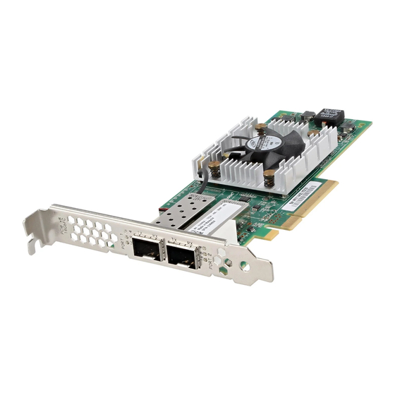
Summary of Contents for Dell MARVELL QLogic QLE2660-DEL
- Page 1 Cover User’s Guide Fibre Channel Adapter QLE2660-DEL, QLE2662-DEL, QME2662-DEL, QLE2690-DEL, QLE2690L-DEL, QLE2692-DEL, QLE2692L-DEL, and QME2692-DEL Third party information brought to you courtesy of Dell. CU0354604-00 P June 12, 2019 Marvell. Moving Forward Faster...
- Page 2 User’s Guide Fibre Channel Adapter For more information, visit our website at: http://www.marvell.com Notice THIS DOCUMENT AND THE INFORMATION FURNISHED IN THIS DOCUMENT ARE PROVIDED “AS IS” WITHOUT ANY WARRANTY. MARVELL EXPRESSLY DISCLAIMS AND MAKES NO WARRANTIES OR GUARANTEES REGARDING THE PRODUCT, WHETHER EXPRESS, ORAL, IMPLIED, STATUTORY, ARISING BY OPERATION OF LAW, OR AS A RESULT OF USAGE OF TRADE, COURSE OF DEALING, OR COURSE OF PERFORMANCE, INCLUDING THE IMPLIED WARRANTIES OF MERCHANTABILITY AND FITNESS FOR PARTICULAR PURPOSE AND NON-INFRINGEMENT.
-
Page 3: Table Of Contents
Windows Driver Installation and Configuration..... . . Running the Dell Update Package in the GUI .... - Page 4 Updating the Dell Firmware ........
- Page 5 User’s Guide—Fibre Channel Adapter QLE266x-DEL, QLE269x-DEL, QLE269xL-DEL, and QME26x2-DEL Setting Fibre Channel Adapter Parameters ......Setting Fibre Channel Adapter Parameters with QConvergeConsole GUI .
- Page 6 User’s Guide—Fibre Channel Adapter QLE266x-DEL, QLE269x-DEL, QLE269xL-DEL, and QME26x2-DEL Setting Queue Depth ......... . Changing the Windows Queue Depth .
- Page 7 User’s Guide—Fibre Channel Adapter QLE266x-DEL, QLE269x-DEL, QLE269xL-DEL, and QME26x2-DEL Configuring CS_CTL QoS ........CS_CTL QoS Features .
- Page 8 User’s Guide—Fibre Channel Adapter QLE266x-DEL, QLE269x-DEL, QLE269xL-DEL, and QME26x2-DEL Limitations and Known Issues ........Unloading and Reloading the Linux Driver.
- Page 9 User’s Guide—Fibre Channel Adapter QLE266x-DEL, QLE269x-DEL, QLE269xL-DEL, and QME26x2-DEL Regulatory Information Warranty ........... . Regulatory and Compliance Information .
- Page 10 Introduction This introductory chapter provides a list of the covered models, describes the intended audience and contents of this guide, lists related documents and the document conventions, describes the product functionality and features, and lists the supported OSs. This user’s guide covers the following products: ®...
-
Page 11: Introduction
Introduction Intended Audience Intended Audience This guide is intended for system administrators and other technical staff ® members responsible for configuring and managing adapters installed on Dell PowerEdge ® servers in Windows ® , Linux ® , or VMware ®... -
Page 12: Related Materials
Introduction Related Materials Related Materials For additional information, refer to the following QLogic documents: QConvergeConsole Help, available after installing QConvergeConsole GUI, provides help topics on configuring and managing host servers and adapters using QConvergeConsole GUI. Installation Guide—QConvergeConsole GUI (part number SN0051105-00) contains instructions for installing and starting QConvergeConsole GUI. - Page 13 Introduction Documentation Conventions Text in bold font indicates user interface elements such as a menu items, buttons, check boxes, or column headings. For example: Click Start, point to Programs, point to Accessories, and then click Command Prompt. Under Notification Options, select the Warning Alarms check box. ...
-
Page 14: Functionality And Features
Introduction Functionality and Features [ ] (square brackets) indicate an optional parameter. For example: [<file_name>] means specify a file name, or omit it to select the default file name. | (vertical bar) indicates mutually exclusive options; select one option ... -
Page 15: Key Features
VMware ESXi. Supported Operating Systems NOTE Because the Dell Update Packages Version xx.xx.xxx User’s Guide is not updated in the same cycle as this Fibre Channel adapter user’s guide, consider the operating systems listed in this section as the more current. -
Page 16: Red Hat
Introduction Functionality and Features Red Hat Red Hat ® Enterprise Linux (RHEL ® ) 8.0 RHEL 7.6 RHEL 7.5 SuSE ® ® SuSE Linux Enterprise Server (SLES ) 15 SP1 SLES 15 SLES 12 SP3 VMware ... -
Page 17: Hardware Installation
For QLE2660-DEL, QLE2662-DEL, QLE2690-DEL, QLE2690L-DEL, QLE2692-DEL, and QLE2692L-DEL adapter port and slot assignments, refer to the “Expansion Cards” section of the Hardware Owner’s Manual for your Dell PowerEdge server. For QME2662-DEL and QME2692-DEL adapter port and slot assignments, refer to the blade and M1000e chassis diagram in the Dell PowerEdge M1000e Systems Configuration Guide. -
Page 18: Pre-Installation Checklist
“Hardware and Software Requirements” on page Verify that your system is using the latest BIOS. NOTE If you acquired the adapter software on a disk or from the Dell support Web site (http://support.dell.com), verify the path to the adapter driver files. -
Page 19: Installing The Adapter
Refasten the adapter’s retaining bracket. Close the computer cover. Plug the Fibre Channel cable into the adapter. Plug in the power cable and turn on the computer. For more detailed information, refer to the Hardware Owner’s Manual for your Dell PowerEdge server. CU0354604-00 P... -
Page 20: Connecting To The San
Follow the instructions for your adapter model number. QLE2660-DEL, QLE2662-DEL, QLE2690-DEL, QLE2690L-DEL, QLE2692-DEL, and QLE2692L-DEL To connect to the SAN, refer to the Hardware Owner’s Manual for your Dell PowerEdge server. QME2662-DEL and QME2692-DEL To connect to the SAN, refer to the “Guidelines for Installing I/O Modules” section of the Dell PowerEdge Modular Systems Hardware Owner’s Manual:... -
Page 21: Driver Installation And Configuration
Driver Installation and Configuration NOTE If you need to update the Flash memory of multiple adapters simultaneously: For QConvergeConsole GUI, refer to the “Update the Flash Using the Flash Update Wizard” topic in the QConvergeConsole Help. For QConvergeConsole CLI, issue the -flashsupport command to update the Flash memory for all cards supported by the specified file. -
Page 22: Windows Driver Installation And Configuration
For the adapter to recognize the storage and LUNs, you must load the adapter drivers a second time. You can run a software or driver Dell Update Package (DUP) in two ways: Running the Dell Update Package in the GUI ... - Page 23 2–Driver Installation and Configuration Windows Driver Installation and Configuration In the QLogic Super Installer—InstallShield ® Wizard’s Welcome window (Figure 2-2), click Next. Figure 2-2. QLogic InstallShield Wizard: Welcome Window In the wizard’s License Agreement window (Figure 2-3): Read the QLogic End User Software License Agreement. To continue, select I accept the terms in the license agreement.
- Page 24 2–Driver Installation and Configuration Windows Driver Installation and Configuration Complete the wizard’s Setup Type window (Figure 2-4) as follows: Select one of the following setup types: Click Complete to install all program features. Click Custom to manually select the features to be installed. ...
- Page 25 2–Driver Installation and Configuration Windows Driver Installation and Configuration Click Next to continue. Figure 2-5. InstallShield Wizard: Custom Setup Window In the InstallShield Wizard’s Ready To Install window (Figure 2-6), click Install. Figure 2-6. InstallShield Wizard: Ready to Install the Program Window CU0354604-00 P...
- Page 26 2–Driver Installation and Configuration Windows Driver Installation and Configuration The InstallShield Wizard installs the QLogic Adapter drivers and Management Software Installer. When the installation is complete, the InstallShield Wizard Completed window appears (Figure 2-7). Click Finish to dismiss the installer. Figure 2-7.
-
Page 27: Running The Dell Update Package From The Command Line
Running the Dell Update Package from the Command Line For a list of the CLI options for systems running Windows, a description of each option, and the command syntax, refer to the Dell Update Packages Version xx.xx.xxx User’s Guide, “Windows CLI Options” section. -
Page 28: Examples
2–Driver Installation and Configuration Linux Driver Installation and Configuration Examples To update the system silently: <DUP_file_name>.exe /s To extract the update contents to the C:\mydir\ directory: <DUP_file_name>.exe /s /e=C:\mydir To extract the driver components to the C:\mydir\ directory: <DUP_file_name>.exe /s /drivers=C:\mydir To install only the driver components: <DUP_file_name>.exe /s /driveronly To change from the default log location to C:\my path with... -
Page 29: Installing The Linux Fibre Channel Driver
2–Driver Installation and Configuration Linux Driver Installation and Configuration Installing the Linux Fibre Channel Driver This section provides procedures for installing the Linux Fibre Channel driver for the following operating systems: Building the Driver for RHEL 7.x and 8.x ... -
Page 30: Building The Driver For Sles 12 Sp3 And Sles 15/15 Sp 1
2–Driver Installation and Configuration Linux Driver Installation and Configuration (Optional) To automatically load the driver each time the system boots, rebuild the RAM disk to include the driver as follows: Create a backup copy of the RAMDISK image by issuing the following commands: # cd /boot # cp initramfs-[kernel version].img initramfs-[kernel... -
Page 31: Vmware Driver Installation And Configuration
2–Driver Installation and Configuration VMware Driver Installation and Configuration (Optional) Manually load the driver for Linux. Edit the /etc/modprobe.d/unsupported_modules file to make the following change: with allow_unsupported_modules 1 (replace 0 To load the driver using modprobe, issue the following command: # modprobe -v qla2xxx ... -
Page 32: Installing The Esxi 6.7 U2 And 6.5 U3 Fibre Channel Driver
2–Driver Installation and Configuration VMware Driver Installation and Configuration Installing the ESXi 6.7 U2 and 6.5 U3 Fibre Channel Driver The operating system manages and controls the driver installation process. To install the ESXi driver, follow the steps in this section. NOTE This section provides the most common ways of installing and upgrading the driver. -
Page 33: Verifying The Version Of The Installed Driver
2–Driver Installation and Configuration VMware Driver Installation and Configuration Verifying the Version of the Installed Driver To verify the installed package in the system, issue the following command: esxcli software vib list | grep qlnativefc The driver version is embedded in the VIB version. For example, the output looks like the following: # esxcli software vib list | grep qlnativefc qlnativefc... -
Page 34: Installation Package Contents
2–Driver Installation and Configuration VMware Driver Installation and Configuration Installation Package Contents The latest version of the QLogic Adapter CIM Provider and QConvergeConsole VMware vCenter Server Plug-in package contains the files needed to install both the Plug-in and the CIM Provider. Required files include the following (where x_x_x is the version number): ... - Page 35 2–Driver Installation and Configuration VMware Driver Installation and Configuration The InstallAnywhere wizard opens, as shown in Figure 2-9. Figure 2-9. InstallAnywhere Initial Window In the QLogic Adapter VI Plug-in wizard’s Introduction window (see Figure 2-10), click Next. Figure 2-10. QLogic Adapter VI Plug-in Wizard: Introduction CU0354604-00 P...
- Page 36 2–Driver Installation and Configuration VMware Driver Installation and Configuration Wait while the wizard configures the plug-in (see Figure 2-11). Figure 2-11. QLogic Adapter VI Plug-in Wizard: Configuring the Plug-in Select the installation directory, and then click Install (see Figure 2-12). Figure 2-12.
- Page 37 2–Driver Installation and Configuration VMware Driver Installation and Configuration Wait while the wizard performs the installation (see Figure 2-13). Figure 2-13. QLogic Adapter VI Plug-in Wizard: Installing the Plug-In CU0354604-00 P...
- Page 38 2–Driver Installation and Configuration VMware Driver Installation and Configuration Type the requested information in the boxes, and then click Next (see Figure 2-14). Figure 2-14. QLogic Adapter VI Plug-in Wizard: User Input Wait while the wizard finishes configuring the plug-in (see Figure 2-15).
-
Page 39: Plug-In Unregistration From A Manual Install
2–Driver Installation and Configuration VMware Driver Installation and Configuration When the Registration Result window (Figure 2-16) appears, click Finish to exit. Figure 2-16. QLogic Adapter VI Plug-in Wizard: Registration Result ™ After the installation completes, restart the Tomcat service as follows: If the plug-in is installed on the VMware vCenter Server, restart the ... -
Page 40: Uninstalling The Qconvergeconsole Vmware Vcenter Server Plug-In
2–Driver Installation and Configuration VMware Driver Installation and Configuration Before you can use the script, you must download the appropriate VI SDK from VMware: For Perl VI SDK, download vSphere SDK for Perl: http://www.vmware.com/support/developer/viperltoolkit/ For PowerShell, download vSphere PowerCLI: http://communities.vmware.com/community/vmtn/vsphere/automationtools/ powercli After downloading and installing the SDK and the registration script, follow the... - Page 41 2–Driver Installation and Configuration VMware Driver Installation and Configuration Initial Installation Methods Initial installation methods for the CIM Provider include the following: Online. Refer to “Installing the CIM Provider on an ESXi 6.7 U2 or 6.5 U3 Host” on page Offline.
- Page 42 2–Driver Installation and Configuration VMware Driver Installation and Configuration To install the asynchronous drivers: Extract the contents of the asynchronous driver zip file. Identify the offline-bundle.zip file or files. From vCenter Server, go to Home, and then select Update Manager. Click the Patch Repository tab.
-
Page 43: Uninstalling The Qlogic Adapter Cim Provider
2–Driver Installation and Configuration VMware Driver Installation and Configuration Subsequent Update Installation To update the QLogic Adapter CIM Provider after a prior VIB installation, follow the instructions in “Uninstalling the QLogic Adapter CIM Provider” on page 27 remove the existing VIB. After completing the VIB removal, use the same steps in “Initial Installation Methods”... -
Page 44: Installing The Qconvergeconsole Vmware Vsphere Web Client Plug-In
2–Driver Installation and Configuration VMware Driver Installation and Configuration To uninstall the CIM Provider from a remote host: NOTE Before performing this procedure, make sure that the ESXi system is in Maintenance Mode. To do so using the vSphere Client, select Inventory, select Host, and then select Enter Maintenance Mode. -
Page 45: Installing Qconvergeconsole Vmware Vsphere Web Client Plug-In
2–Driver Installation and Configuration VMware Driver Installation and Configuration Installing QConvergeConsole VMware vSphere Web Client Plug-in Run the installer on the server providing the Tomcat service. Enter the information requested by the installer. On Windows, double-click the installer and follow the instructions on the GUI provided. -
Page 46: Uninstalling The Qconvergeconsole Vmware Vsphere Web Client Plug-In
2–Driver Installation and Configuration VMware Driver Installation and Configuration Uninstalling the QConvergeConsole VMware vSphere Web Client Plug-in To uninstall the QConvergeConsole VMware vSphere Web Client Plug-in, refer to the procedure for Windows or Linux: Windows. Uninstall the QConvergeConsole VMware vSphere Web Client Plug-in on Windows using the Windows Control Panel Uninstall Program window. -
Page 47: Fibre Channel Configuration
Fibre Channel Configuration This chapter provides the following information about configuring Fibre Channel: “Updating the Dell Firmware” on page 32 “Using Fast!UTIL for Custom Configuration” on page 36 “Setting Fibre Channel Adapter Parameters” on page 42 “Configuring Target Persistent Binding” on page 43 ... -
Page 48: Updating The Dell Firmware
Updating the Dell Firmware The firmware Dell Update Package (DUP) is a Flash update utility only; it is not used for adapter configuration. To run the firmware DUP, double-click the executable file. Alternatively, run the firmware DUP from the command line, which supports several command line options. - Page 49 Updating the Dell Firmware When the DUP splash screen appears (Figure 3-1), click Install to continue. Figure 3-1. Dell Update Package Splash Screen Follow the installer instructions. If a warning message appears (Figure 3-2), click Yes to continue the installation.
- Page 50 3–Fibre Channel Configuration Updating the Dell Firmware The installer indicates that it is loading the new firmware (Figure 3-3). Figure 3-3. Loading New Firmware When complete, the installer indicates the result of the installation (Figure 3-4). Click Yes to elect to reboot.
-
Page 51: Running The Firmware Update From The Command Line
3–Fibre Channel Configuration Updating the Dell Firmware To complete the installation, click Finish (Figure 3-5). Figure 3-5. Finish Installation Running the Firmware Update from the Command Line Running the firmware DUP from the command line, with no options specified, results in the same behavior as double-clicking the icon representing the DUP. -
Page 52: Using Fast!Util For Custom Configuration
3–Fibre Channel Configuration Using Fast!UTIL for Custom Configuration Figure 3-6 shows the options you can use to customize the DUP installation behavior. Figure 3-6. Command Line Options Using Fast!UTIL for Custom Configuration This section provides detailed configuration information for advanced users who want to customize the configuration of the adapters and connected devices using Fast!UTIL (the QLogic Fibre Channel Adapter BIOS utility) in a pre-OS environment. -
Page 53: Configuration Settings
3–Fibre Channel Configuration Using Fast!UTIL for Custom Configuration A message indicates that the configuration settings have been modified. Select Save changes. To load the new parameters, reboot the system. CAUTION If the configuration settings are incorrect, your 2600 Series Adapter may not function properly. - Page 54 3–Fibre Channel Configuration Using Fast!UTIL for Custom Configuration Table 3-1. Adapter Settings (Continued) Setting Values Default Description 512, 1024, 2048 This setting specifies the maximum frame length supported Frame Size 2048 by the 2600 Series Adapter. 0–60 After resetting the loop, the firmware refrains from initiating Loop Reset seconds seconds...
-
Page 55: Selectable Boot Settings
3–Fibre Channel Configuration Using Fast!UTIL for Custom Configuration Selectable Boot Settings The Configuration Settings menu provides access to the Selectable Boot Settings options. If you enable the Host Bus Adapter BIOS in the adapter settings, you can select the boot device, as shown in Table 3-2. -
Page 56: Restore Default Settings
3–Fibre Channel Configuration Using Fast!UTIL for Custom Configuration NOTE System BIOS compatibility: To boot from a QLogic host 2600 Series Adapter in a computer system with a multiboot system BIOS, the 2600 Series Adapter must be included in the list of bootable devices in the system’s Boot menu. -
Page 57: Scan Fibre Devices
3–Fibre Channel Configuration Using Fast!UTIL for Custom Configuration Table 3-3. Advanced Adapter Settings (Continued) Setting Values Default Description 0–255 This setting specifies the number of seconds the software Port Down seconds seconds waits before resending a command to a port whose status Retry indicates that the port is down. -
Page 58: Loopback Data Test
3–Fibre Channel Configuration Setting Fibre Channel Adapter Parameters Verify the disk data (Some targets do not support this feature.) Select a disk device CAUTION Performing a low-level format destroys all data on the disk. Loopback Data Test The Loopback Data Test option allows you to perform the following loopback tests: ... -
Page 59: Setting Fibre Channel Adapter Parameters With
3–Fibre Channel Configuration Configuring Target Persistent Binding Setting Fibre Channel Adapter Parameters with QConvergeConsole GUI For information about how to set Fibre Channel adapter parameters using QConvergeConsole GUI, refer to the topic about managing Fibre Channel and Fibre Channel over Ethernet (FCoE) adapter ports in the QConvergeConsole Help. -
Page 60: Configuring Persistent Binding With Qconvergeconsole Gui
3–Fibre Channel Configuration Configuring Target Persistent Binding Configuring Persistent Binding with QConvergeConsole GUI To bind target devices attached to an adapter port using QConvergeConsole GUI: In the system tree, expand a Fibre Channel node. In the system tree for a 2600 Series Adapter, select the physical port number. -
Page 61: Configuring Persistent Binding With Noninteractive
3–Fibre Channel Configuration Configuring Boot Devices Configuring Persistent Binding with Noninteractive QConvergeConsole CLI To bind a selected target to a specific adapter using the noninteractive mode of QConvergeConsole CLI, issue the following command: # qaucli -pr fc -p (<hba instance> | <hba wwpn>) (<target wwnn> <target wwpn>... -
Page 62: Configuring Boot Devices With Noninteractive
3–Fibre Channel Configuration Configuring Virtual Ports (NPIV) For information, refer to the section about the Fibre Channel interactive commands in the User’s Guide—QConvergeConsole CLI (part number SN0054667-00). Configuring Boot Devices with Noninteractive QConvergeConsole CLI To set a specific target as the boot device for a specific adapter, issue the following command: # qaucli -pr fc -e (<hba instance>... -
Page 63: Configuring Npiv With Qconvergeconsole Gui
3–Fibre Channel Configuration Configuring Virtual Ports (NPIV) Configuring NPIV with QConvergeConsole GUI For information about using virtualization (NPIV) in QConvergeConsole GUI, refer to in the QConvergeConsole Help. To access the QConvergeConsole Help system while the GUI utility is running, point to the gear icon , point to Help, and then click Browse Contents. -
Page 64: Configuring Npiv Quality Of Service
3–Fibre Channel Configuration Configuring Virtual Ports (NPIV) Configuring NPIV Quality of Service The QLogic 2600 Series Adapters solution provides for standards-based quality of service (QoS), ensuring high-quality performance for applications that require preferential delivery. The QLogic QoS solution is based on assigning QoS levels to virtual ports (NPIV ports). -
Page 65: Setting Qos By Bandwidth
Windows Server 2012 or later Server support for MSI-X QLogic 2600 Series Adapter Latest version of the QLogic STOR miniport driver, available from Dell: http://support.dell.com Fibre Channel switch that supports NPIV Physical port attached in a point-to-point connection Setting QoS by Bandwidth Setting the QoS by bandwidth allocates up to 80 percent of the physical port’s... - Page 66 3–Fibre Channel Configuration Configuring Virtual Ports (NPIV) When the physical port is partitioned into four virtual ports, the port bandwidth is divided between the virtual ports according to traffic demands. QConvergeConsole lets you configure QoS for each virtual port by setting minimum and maximum percentages of the physical port’s bandwidth for each virtual port.
- Page 67 3–Fibre Channel Configuration Configuring Virtual Ports (NPIV) To set the QoS by bandwidth speed with QConvergeConsole GUI: In the QConvergeConsole tree pane on the left, expand a 2600 Series Adapter. Select a virtual port. In the content pane on the right, click the QoS tab. In the QoS Type box, select Bandwidth.
-
Page 68: Setting Qos By Priority
3–Fibre Channel Configuration Configuring Virtual Ports (NPIV) Setting QoS by Priority To set the QoS by priority with QConvergeConsole GUI: In the QConvergeConsole tree pane on the left, expand a 2600 Series Adapter. Select a virtual port. In the content pane on the right, click the QoS tab. In the QoS Type box, select Priority. -
Page 69: Configuring Fibre Channel Driver Parameters
3–Fibre Channel Configuration Configuring Fibre Channel Driver Parameters Configuring Fibre Channel Driver Parameters Use QConvergeConsole GUI, CLI, or VMware plug-in to configure Fibre Channel driver parameters: Configuring Fibre Channel Driver Parameters with QConvergeConsole GUI Configuring Fibre Channel Driver Parameters with Interactive QConvergeConsole CLI ... -
Page 70: Qconvergeconsole Cli
3–Fibre Channel Configuration Configuring Selective LUNs Configuring Fibre Channel Driver Parameters with Noninteractive QConvergeConsole CLI To configure driver settings, issue the following command: # qaucli -pr fc -fs (<hba instance> | <hba wwpn>) {(<param name> | <param alias>) <param value>} Where: hba instance = Adapter number (use the -g command to find) hba wwpn = Worldwide port name of the adapter... -
Page 71: Configuring Ooofr
3–Fibre Channel Configuration Configuring OoOFR Configuring OoOFR Out-of-order frame reassembly (OoOFR) reassembles out-of-order frames as they are received, minimizing network congestion by eliminating the retransmission of frames and exchanges. To configure OoOFR, use either QConvergeConsole GUI or CLI. Configuring OoOFR with QCC GUI To enable OoOFR with QConvergeConsole GUI: In the QConvergeConsole system tree pane on the left, select a Fibre Channel port. -
Page 72: Configuring The Uefi Driver
To configure the UEFI driver for Dell: During system boot, press the key corresponding to your platform. On the Dell System Setup window, select Device Settings, and then press the ENTER key. The Device Settings window opens and lists the devices installed in the system. - Page 73 Configuration Page is the top-level menu of the adapter configuration pages. Figure 3-12 shows an example of the Main Configuration Page. Figure 3-12. Dell System Setup: Main Configuration On the Main Configuration Page, select Port Configuration Page and press ENTER.
- Page 74 3–Fibre Channel Configuration Configuring the UEFI Driver Use the Port Configuration Page to change adapter operational parameters, such as port speed. In most cases, use the default values. Table 3-4 describes the configurable options on the Port Configuration Page. Table 3-4. Port Configuration Page Settings Setting Description Device Name...
- Page 75 The Firmware and Device Information page provides the adapter and firmware version information, and port address information. Figure 3-14 shows an example. Figure 3-14. Dell System Setup: Firmware and Device Information Table 3-5 describes the Firmware and Device Information settings. Table 3-5. Firmware and Device Information Settings...
- Page 76 3–Fibre Channel Configuration Configuring the UEFI Driver On the Main Configuration Page, select Fibre Channel Target Configuration, and then press ENTER. The Fibre Channel Target Configuration page appears. Figure 3-15 shows an example. Figure 3-15. Fibre Channel Target Configuration CU0354604-00 P...
- Page 77 3–Fibre Channel Configuration Configuring the UEFI Driver On the Fibre Channel Target Configuration page, select SAN storage devices for boot from SAN. With selective boot scan enabled, the target configuration determines which target LUNs to map. All other devices are ignored.
- Page 78 ENTER. The HBA Configuration Page appears; Figure 3-16 shows an example. Figure 3-16. Dell System Setup: HBA Configuration Use the HBA Configuration Page to configure adapter operational parameters. In most cases, use the default values. Table 3-7 describes the fields on the HBA Configuration Page.
-
Page 79: Setting Queue Depth
3–Fibre Channel Configuration Setting Queue Depth Table 3-7. HBA Configuration Page Settings (Continued) Setting Description Port Login Timeout Specifies the time-out in milliseconds that the initiator uses when attempting to log in to the target device port. The range is 0 to 255000. Port Down Retry Count Specifies the number of seconds the software retries a command to a port returning port-down status. -
Page 80: Changing The Windows Queue Depth
3–Fibre Channel Configuration Setting Queue Depth Changing the Windows Queue Depth The default queue depth value on Windows is 20 and the range is 0–254. To change the default value: Click Start, select Run, and open the REGEDIT/REGEDT32 program. Select HKEY_LOCAL_MACHINE and then expand the tree structure down to the QLogic driver as follows: HKEY_LOCAL_MACHINE SYSTEM... -
Page 81: Changing The Esxi Queue Depth
3–Fibre Channel Configuration Setting an FA-PWWN Changing the ESXi Queue Depth The default queue depth value on ESXi is 64 and the range is 0–65535. To change the default value: Issue the following command: $ esxcfg-module -s "ql2xmaxqdepth=X" qlnativefc where X is the new queue depth value. Restart the system. -
Page 82: Setting Fa-Pwwn With Qconvergeconsole Gui
3–Fibre Channel Configuration Setting an FA-PWWN Setting FA-PWWN with QConvergeConsole GUI Before setting the FA-PWWN, the port name appears on the Port Info page as shown in the example in Figure 3-17. Figure 3-17. Before Setting the FA-PWWN in the GUI To set the FA-PWWN from the adapter using QConvergeConsole GUI: In the QConvergeConsole GUI tree pane on the left, select an adapter, expand the adapter node, and then select a port. -
Page 83: Setting Fa-Pwwn With Qconvergeconsole Cli
3–Fibre Channel Configuration Setting an FA-PWWN After refreshing the Brocade ® switch, the Port Info page shows the Port Name as shown in Figure 3-18. Figure 3-18. New FA-PWNN Port Name in GUI Setting FA-PWWN with QConvergeConsole CLI To set the FA-PWWN from the adapter using QConvergeConsole CLI: In the interactive mode of QConvergeConsole CLI, select Main Menu, and then click Adapter Configuration. - Page 84 3–Fibre Channel Configuration Setting an FA-PWWN 5: Hard Loop ID 6: Loop Reset Delay (seconds) 7: Enable BIOS 8: Enable Fibre Channel Tape Support 9: Operation Mode 10: Interrupt Delay Timer (100 microseconds) 11: Execution Throttle 12: Login Retry Count 13: Port Down Retry Count 14: Enable LIP Full Login 15: Link Down Timeout (seconds)
-
Page 85: Setting Fa-Pwwn With Qconvergeconsole Vmware Plug-Ins
3–Fibre Channel Configuration Setting an FA-PWWN After refreshing the Brocade switch, the Adapter Information shows the port name as shown in the following example. QConvergeConsole CLI - Version 1.1.3 (Build 22) FC Adapter Information 1: FC Adapter Information 2: FC Port Information 3: FC VPD Information 4: FC Target/LUN Information 5: FC VFC Information... -
Page 86: Setting The Fa-Pwwn From The Brocade Switch
3–Fibre Channel Configuration Setting an FA-PWWN Setting the FA-PWWN from the Brocade Switch From the Brocade switch, you can set a FA-PWWN and a static FA-PWWN. For the most current information, refer to the Brocade switch documentation. Setting the FA-PWWN from the Switch Figure 3-19 shows the FA-PWWN setting from the Brocade switch. -
Page 87: Configuring And Verifying Fa-Bld
3–Fibre Channel Configuration Configuring and Verifying FA-BLD After refreshing the Brocade switch, the Device Port WWN appears in Web Tools as shown in Figure 3-22. Figure 3-22. Device Port WWN (Static) for Brocade Switch Configuring and Verifying FA-BLD This section provides the following information on fabric-assigned boot LUN discovery (FA-BLD): Configuring FA-BLD from the Adapter ... - Page 88 3–Fibre Channel Configuration Configuring and Verifying FA-BLD Figure 3-23 shows an example. Figure 3-23. Enabling Host Bus Adapter Port BIOS To enable fabric-assigned boot LUN: In QConvergeConsole GUI, select the Host tab in the left pane. In the system tree, expand the adapter node and then select a port node. In the content pane on the right, click the Parameters tab.
-
Page 89: Configuring The Adapter And Boot Devices With Qconvergeconsole Cli
3–Fibre Channel Configuration Configuring and Verifying FA-BLD Figure 3-24 shows an example. Figure 3-24. Enabling Fabric-Assigned Boot LUN Configuring the Adapter and Boot Devices with QConvergeConsole CLI To configure adapter and boot devices: In QConvergeConsole CLI, navigate to Adapter Configuration and then select HBA Parameters. -
Page 90: Configuring A Zone In A Brocade Switch
3–Fibre Channel Configuration Configuring and Verifying FA-BLD Figure 3-25 shows an example of the adapter and boot device configuration. Figure 3-25. Configuring Adapter and Boot Device Configuring a Zone in a Brocade Switch To configure a zone in a Brocade switch: Create a boot LUN configuration as follows: bootluncfg --add 50:00:53:37:63:FA:00:05 20:02:00:11:0d:51:5c:01 0000000000000000... -
Page 91: Verifying That Fa-Bld Is Operational
3–Fibre Channel Configuration Configuring and Verifying FA-BLD Figure 3-26 shows an example of a configured zone in a Brocade switch. Figure 3-26. Configuring a Zone in a Brocade Switch Verifying that FA-BLD is Operational To verify if the FA-BLD is operational, use either Fast!UTIL or the system. Figure 3-27 shows Fast!UTIL displaying the boot LUN. -
Page 92: Adapter Side Restrictions
3–Fibre Channel Configuration Configuring and Verifying FA-BLD Figure 3-28 shows using the system with a LUN ready to install or OS booted from LUN. Figure 3-28. Verifying FA-BLD from the System Adapter Side Restrictions The known fabric-assigned port world wide name (FA-PWNN) and FA-BLD restrictions include the following: ... -
Page 93: Using A Fabric-Assigned Boot Lun
3–Fibre Channel Configuration Using a Fabric-Assigned Boot LUN Using a Fabric-Assigned Boot LUN This section describes how to use a fabric-assigned boot LUN in the following utilities: Using a Fabric-Assigned Boot LUN in QConvergeConsole GUI Using a Fabric-Assigned Boot LUN in Interactive QConvergeConsole CLI ... -
Page 94: Using A Fabric-Assigned Boot Lun With Qconvergeconsole Plug-Ins
3–Fibre Channel Configuration Using a Fabric-Assigned Boot LUN Using a Fabric-Assigned Boot LUN with QConvergeConsole Plug-ins For information about using a fabric-assigned boot LUN for QConvergeConsole VMware vSphere Web Client Plug-in, see the section “Configure Fibre Channel Port Boot Parameters” in the User’s Guide—QConvergeConsole Plug-ins for VMware vSphere (part number SN0054677-00). -
Page 95: Running Diagnostics-Fibre Channel Ping And Trace Route
3–Fibre Channel Configuration Running Diagnostics—Fibre Channel Ping and Trace Route Running Diagnostics—Fibre Channel Ping and Trace Route This section provides the following information on how to run Fibre Channel ping and trace route diagnostics: Pinging and Viewing Trace of Routing Using Topology Map ... -
Page 96: Running A Fibre Channel Ct Ping Test
3–Fibre Channel Configuration Running Diagnostics—Fibre Channel Ping and Trace Route Running a Fibre Channel CT Ping Test You can run a Fibre Channel CT ping test from QConvergeConsole GUI, QConvergeConsole CLI, or the QConvergeConsole VMware plug-ins, as described in this section. Running a Fibre Channel CT Ping from QConvergeConsole GUI To run a Fibre Channel CT ping test from QConvergeConsole GUI: In the QConvergeConsole GUI left pane, click the Host tab. -
Page 97: Running A Fibre Channel Ct Ping From Qconvergeconsole Cli
3–Fibre Channel Configuration Running Diagnostics—Fibre Channel Ping and Trace Route A caution message appears for the diagnostic CT ping test (Figure 3-31). Figure 3-31. CT Ping Test Caution Ensure that the port has no active I/O operations, and then either click Yes to proceed or No to cancel the test. -
Page 98: Running A Fibre Channel Ct Ping From Qconvergeconsole Vmware Plug-Ins
3–Fibre Channel Configuration Running Diagnostics—Fibre Channel Ping and Trace Route Data Link Sync Signal Invalid Diagnostic Port/Loop Miscompare Failure Loss Loss Status --------- ---------- ------- -------- --------- --------- ---------- 01-0B-01 Success NOTE The default setting will repeat 10 times with output similar to the preceding for each pass of the test. - Page 99 3–Fibre Channel Configuration Running Diagnostics—Fibre Channel Ping and Trace Route Figure 3-32 shows an example. Figure 3-32. Running Fibre Channel Trace Route from QConvergeConsole GUI The Fibre Channel trace route output from QConvergeConsole GUI shows a symbol of a red payload that starts from the host. The travel across the route is also highlighted in red.
-
Page 100: Configuring Cs_Ctl Qos
3–Fibre Channel Configuration Configuring CS_CTL QoS Configuring CS_CTL QoS NOTE For information about end-to-end CS_CTL QoS, see “Configuring End-to-End CS_CTL QoS” on page This section provides the following information on class-specific control (CS_CTL) quality of service (QoS): CS_CTL QoS Features ... -
Page 101: Enabling Cs_Ctl Qos Mode For The Initiator And Target Ports
3–Fibre Channel Configuration Configuring CS_CTL QoS Enabling CS_CTL QoS Mode for the Initiator and Target Ports Figure 3-33 shows how to enable CS_CTL QoS mode for the initiator and target ports. Figure 3-33. Enabling CS_CTL QoS Mode Verifying and Confirming CS_CTL Mode Setup for Each Port Figure 3-34 shows how to verify the CS_CTL mode setup for each port. - Page 102 3–Fibre Channel Configuration Configuring CS_CTL QoS Figure 3-35 shows how to create a virtual port from the adapter’s port in QConvergeConsole GUI. Figure 3-35. Creating a Virtual Port CU0354604-00 P...
-
Page 103: Setting The Qos Priority Level For A Virtual Port In Qconvergeconsole Gui
3–Fibre Channel Configuration Configuring End-to-End CS_CTL QoS Setting the QoS Priority Level for a Virtual Port in QConvergeConsole GUI Figure 3-36 shows how to set the QoS priority level for a virtual port in QConvergeConsole GUI. Figure 3-36. Setting the QoS Priority Level NOTE By default, the QoS of the physical port is set to High, and the QoS of the virtual port is set to Low. -
Page 104: Configuring Cs_Ctl Qos On The Switch
3–Fibre Channel Configuration Configuring End-to-End CS_CTL QoS Therefore, when all three entities support QoS (and it is enabled on the switch and the target), a default priority value is populated in all FCP_CMND, FCP_DATA, FCP_XFER_RDY, FCP_RSP, and FCP_CONFIRM frames. NOTE QoS must be supported by both the switch and target devices. -
Page 105: Configuring Cs_Ctl Qos On The Storage Device
3–Fibre Channel Configuration Configuring End-to-End CS_CTL QoS To verify that CS_CTL QoS is enabled, issue the following command: root> configshow -all | grep fos.csctlMode This command should return the following response: fos.csctlMode:1 To enable QoS on a switch-port basis, issue the following command: portcfgqos --enable [slot/]port csctl_mode Configuring CS_CTL QoS on the Storage Device See your device’s user guide for QoS configuration instructions. - Page 106 3–Fibre Channel Configuration Configuring End-to-End CS_CTL QoS To create the vPorts, click Create. Figure 3-37 shows an example. Figure 3-37. Creating vPorts in QConvergeConsole GUI To create a vPort in interactive QConvergeConsole CLI: On the Main Menu, select Adapter Configuration. On the Adapter Type Selection menu, select Virtual Ports (NPIV).
-
Page 107: Changing The Priority Levels In Vmware Esxi
3–Fibre Channel Configuration Configuring End-to-End CS_CTL QoS Set the QoS priority value for the vPort by moving the corresponding slider. Repeat Step 6 Step 7 for each vPort whose priority you want to change. Click Save. Figure 3-38 shows an example. Figure 3-38. - Page 108 3–Fibre Channel Configuration Configuring End-to-End CS_CTL QoS Set the vPort priority as follows: If the vPort is listed under QoS: Select the vPort. Set the QoS priority value for the vPort by moving the corresponding slider. Click Save. Figure 3-39 shows an example.
-
Page 109: Configuring Fdmi
3–Fibre Channel Configuration Configuring FDMI Configuring FDMI The fabric device management interface (FDMI) enables the centralized management of devices such as host adapters. Supported configuration for FDMI: QLogic 2500 and 2600 Series Adapters Brocade 16G switches with Fabric OS (FOS) v7.3 or later Cisco 16G switches with NX-OS v8.3.1 or later ... -
Page 110: Brocade Switch Fos Cli
3–Fibre Channel Configuration Configuring FDMI Brocade Switch FOS CLI Figure 3-40 shows the FOS CLI of a Brocade switch. Figure 3-40. FOS CLI of Brocade Switch CU0354604-00 P... -
Page 111: Fabric Features
3–Fibre Channel Configuration Configuring FDMI Fabric Features Table 3-9 shows the default configuration for Brocade Fibre Channel fabric features. Table 3-9. Brocade Fibre Channel Fabric Features—Default Configuration Feature Description Management Tools Default Configuration D_Port Diagnostics port Diagnostic test; run from support switch. -
Page 112: Fdmi Enhancements Support
FDMI attributes Nothing to configure on Enhancements adapter. Table 3-11 lists the minimum Dell software version of the Fibre Channel fabric features for both Brocade and Cisco. Table 3-11. Fibre Channel Fabric Features, Software Version Component Dell Software Version Firmware v15.00.00... - Page 113 3–Fibre Channel Configuration Configuring FDMI To verify the additional QLogic adapter attributes registered on the Brocade switch, issue the fdmishow command on Brocade Fibre Channel switches to confirm that all the requested attributes are displayed in the switch. For details, see the Brocade switch documentation.
-
Page 114: Enabling Qlogic Forward Error Correction
3–Fibre Channel Configuration Enabling QLogic Forward Error Correction ROM Ver :3.62 Firmware Ver :8.08.03 (d0d5) Port-id: 21:00:00:24:ff:8f:d8:88 Supported FC4 types:scsi-fcp Supported Speed :4G 8G 16G Current Speed :16G Maximum Frame Size :2048 OS Device Name :qla2xxx:host1 Host Name :localhost.localdomain Enabling QLogic Forward Error Correction QConvergeConsole supports the forward error correction (FEC) feature, which is a correction technique used for high-speed telecommunications devices to control errors in data transmission over unreliable or noisy communication channels. -
Page 115: Enabling Qlogic Fec
3–Fibre Channel Configuration Enabling QLogic Forward Error Correction NOTE Instead of having to request retransmission of the entire data frame, the receiving device can recreate or reconstruct the data stream itself. This process prevents multiple CRC errors from being triggered and causing application performance issues. -
Page 116: Running Extended Link Service Commands
3–Fibre Channel Configuration Running Extended Link Service Commands Figure 3-41, the QConvergeConsole CLI interactive mode Adapter Information menu shows a port with an online FEC status. Figure 3-41. QConvergeConsole CLI Adapter Information Menu, FEC Status Running Extended Link Service Commands Commands for extended link service on the switch include the following: ... -
Page 117: Link Cable Beacon Extended Link Service Command
3–Fibre Channel Configuration Running Extended Link Service Commands Link Cable Beacon Extended Link Service Command NOTE This feature is supported only on QLE2690-DEL and QLE2692-DEL Adapters. Run the LCB test only from a switch with either FOS version 7.4.x or later, or Cisco NX-OS 8.3.1 or later. The link cable beacon (LCB) extended link service command locates the corresponding ends of a cable by flashing the specific LEDs on the corresponding ports of a link. - Page 118 3–Fibre Channel Configuration Running Extended Link Service Commands Vendor Name: HP-F BROCADE Vendor OUI: 00:05:1e Vendor PN: QK724A Vendor Rev: Wavelength: (units nm) Options: 003a Loss_of_Sig,Tx_Fault,Tx_Disable BR Max: BR Min: Serial No: HAF314370000B7F Date Code: 140909 DD Type: 0x68 Enh Options: 0xfa Status/Ctrl: 0x30 Pwr On Time: 0.30 years (2666 hours) E-Wrap Control: 0...
- Page 119 3–Fibre Channel Configuration Running Extended Link Service Commands Signal Loss (Downstream): -20.3 dBm (9.4 Port Speed Capabilities 4Gbps 8Gbps 16Gbps Last poll time: 03-24-2015 UTC Tue 18:03:14 CU0354604-00 P...
-
Page 120: Nvm Express Over Fibre Channel Hardware And Software Requirements
NVM Express over Fibre Channel This chapter describes the installation and configuration of NVMe over Fibre Channel (FC-NVMe) on the QLogic adapters from Marvell. It covers: Hardware and Software Requirements “Host Setup” on page 106 “Limitations and Known Issues” on page 113 ... -
Page 121: Host Software
4–NVM Express over Fibre Channel Hardware and Software Requirements Microsoft Windows Server (Tech Preview only): Windows Server 2016 Windows Server 2019 Host Software This section lists the required FC-NVMe software, which, unless stated otherwise, is available on the Marvell Web site (see “Documentation Conventions”... -
Page 122: Host Setup
Linux QLogic management application, QConvergeConsole CLI version 2.3.0.11 or later: QConvergeConsoleCLI-2.3.00-11.x86_64 Windows QLogic management application, QConvergeConsole CLI version 2.3.0.11 or later (available from the Dell site): QConvergeConsoleCLI-2.3.00-11_win_x64.zip NVMe CLI native application: The OS Distribution DVD contains the native ... - Page 123 4–NVM Express over Fibre Channel Host Setup Untar and install the Linux driver kit by issuing the following commands: # tar -zxvf qla2xxx-src-v10.01.00.43.xx.y-k.tar.gz # cd qla2xxx-src-v10.01.00.43.xx.y-k # ./extras/build.sh install The src driver kits and driver RPM kits have embedded FC-NVMe auto-discovery scripts that are installed when the driver is deployed.
- Page 124 4–NVM Express over Fibre Channel Host Setup Edit or create the qla2xxx.conf file to add the ql2xnvmeenable option. For example, /etc/modprobe.d/qla2xxx.conf contains: options qla2xxx ql2xnvmeenable=1 For the FC-NVMe option to take effect the system boot image will need to be updated.
- Page 125 4–NVM Express over Fibre Channel Host Setup NOTE The OOB driver must have the FC-NVMe option enabled to attach to FC-NVMe storage devices. For details on using the FC-NVMe driver option, see either the 10.01.xx.xx.xx.x-x driver documentation or the example shown in Step (Optional) As needed, on the supported Linux OS, create a hostnqn file to attach to remote FC-NVMe Storage Subsystems.
-
Page 126: Windows Host Setup
These procedures apply only to the FC-NVMe driver. For the Fibre Channel driver, follow the instructions in the corresponding Readme.txt file. To set up a Windows host: Install the Windows FC driver from the Dell update package. Driver v9.3.2.20 or greater ... -
Page 127: Verifying The Availability Of Fc-Nvme Devices
4–NVM Express over Fibre Channel Host Setup Choose the HBA instance for the adapter that you want to connect to FC-NVMe devices (0 in this example), and then issue the following command: # qaucli -i 0 Running Firmware Version : 8.08.204 (d0d5) Flash Firmware Version : 8.08.204 The preceding output shows the QLE2692-DEL card with firmware version... -
Page 128: Verifying In Windows
4–NVM Express over Fibre Channel Host Setup Example: nvme list Command The following example of a portion of the nvme list output shows the FC-NVMe attached targets. Node Model Namespace Usage Format FW Rev ------- ------------------- -------- ---- ---- ----------------------- --------- ----------- nvme0n1 00-200100110dd89300 SANBlaze VLUN P3T0 1 67.11 MB / 67.11... -
Page 129: Limitations And Known Issues
4–NVM Express over Fibre Channel Limitations and Known Issues Figure 4-2 shows the devices in Windows Device Manager. Figure 4-2. FC-NVMe Devices in Windows Device Manager NOTE To support formatting of an FC-NVMe drive on Windows, you may need to add the following Windows Registry entry for some OEM storage: [HKEY_LOCAL_MACHINE\SYSTEM\CurrentControlSet\Services\ ql2300\Parameters\Device]"DriverParameter"="ts=1"... -
Page 130: Unloading And Reloading The Linux Driver
4–NVM Express over Fibre Channel Unloading and Reloading the Linux Driver Unloading and Reloading the Linux Driver Follow the instructions in this section to unload and reload the Linux driver. To unload and reload the Linux driver: List all the FC-NVMe connected target controllers by issuing the following command: # ls /dev/nvme* | grep -E nvme[0-9]+$ The preceding command should list all connected /dev/nvme[x]... -
Page 131: Troubleshooting
Troubleshooting This appendix provides information about Fibre Channel diagnostics and a Fibre Channel troubleshooting diagram, including: Fibre Channel Diagnostics “Fibre Channel Troubleshooting Diagram” on page 118 “Troubleshooting with a Diagnostic Port (D_Port)” on page 119 Fibre Channel Diagnostics Troubleshooting with Fibre Channel diagnostics include: Fibre Channel Diagnostics Using QConvergeConsole GUI ... - Page 132 A–Troubleshooting Fibre Channel Diagnostics From the Data Size list, click the number of bytes to transfer. Valid values are 8, 16, 32, 64, 128, 256, 512, 1024 and 2048. For Linux operating systems only, you can select data size values from 2048, 4096, 8192 up to 65535 (2K bytes to 64K bytes).
-
Page 133: Fibre Channel Diagnostics Using Interactive
A–Troubleshooting Fibre Channel Diagnostics To run the beacon on/off test: In the QConvergeConsole GUI main window, click an adapter port in the system tree pane on the left. In the content pane on the right, click the Port Info tab. On the Port Info page, click Beacon On to run the test. -
Page 134: Fibre Channel Troubleshooting Diagram
A–Troubleshooting Fibre Channel Troubleshooting Diagram Fibre Channel Troubleshooting Diagram Figure A-1 Figure A-2 provide a two-part troubleshooting flowchart. Figure A-1. Fibre Channel Troubleshooting Diagram (1 of 2) CU0354604-00 P... -
Page 135: Troubleshooting With A Diagnostic Port (D_Port)
A–Troubleshooting Troubleshooting with a Diagnostic Port (D_Port) Adapter can log into fabric and name server? Co gure Fibre Channel switch for auto- nego a on and Verify that cable is connected return to “Start” and link lights are lit Cable is Fibre Channel Are op cs Check auto-nego a on... -
Page 136: Configuring D_Port On A Brocade Fibre Channel 16G Switch
A–Troubleshooting Troubleshooting with a Diagnostic Port (D_Port) NOTE All QLogic-branded 16GFC SFP+ transceivers can run D_Port tests. If you have a supported non-QLogic branded transceiver, ensure that it supports the optical wrap (OWrap) and electrical wrap (EWrap) capability that is required for D_Port. -
Page 137: Configuring And Running Diagnostics Port On A Cisco Fibre Channel 16 Switch
A–Troubleshooting Troubleshooting with a Diagnostic Port (D_Port) To disable D_Port diagnostic mode: From the Brocade Fibre Channel 16G switch, issue the following commands: # portdisable <port_num> # portcfgdport ––disable <port_num> # portenable <port_num> The D_Port test stops. Configuring and Running Diagnostics Port on a Cisco Fibre Channel 16 Switch The following example configures and starts a diagnostic test on port 2 of a Cisco Fibre Channel 9396S or 97xx switch (NX-OS 8.2.1 or later). -
Page 138: Checking D_Port Results From A Brocade Fibre Channel 16G Switch
A–Troubleshooting Troubleshooting with a Diagnostic Port (D_Port) To disable the diagnostic port, type the following commands: Cisco#int fc 1/2 Cisco(config-if)# shut Cisco(config-if)# no switchport link-diag Cisco(config-if)# no shut Checking D_Port Results from a Brocade Fibre Channel 16G Switch To view the D_Port test results from a Brocade Fibre Channel 16G switch: To get the port number, issue the switchshow command: # switchshow The following example output identifies port 17:... -
Page 139: Verifying D_Port Mode With Qconvergeconsole Gui
A–Troubleshooting Troubleshooting with a Diagnostic Port (D_Port) Optical loopback 01:46:54 PASSED -------- ---------- Link traffic test -------- SKIPPED -------- ---------- ============================================================================== Roundtrip link latency: 157 nano-seconds Estimated cable distance: 3 meters Buffers required: 1 (for 2112 byte frames at 16Gbps speed)s Verifying D_Port Mode with QConvergeConsole GUI To verify D_Port mode in QConvergeConsole GUI: In the QConvergeConsole left pane, click the Host tab. -
Page 140: Verifying D_Port Mode With Noninteractive
A–Troubleshooting Troubleshooting with a Diagnostic Port (D_Port) The Adapter Information menu shows the affected port with a status of Loop Down, Diagnostic Mo. Figure A-4 shows an example. Figure A-4. D_Port Mode in Interactive QConvergeConsole CLI Verifying D_Port Mode with Noninteractive QConvergeConsole CLI To verify D_Port mode in noninteractive QConvergeConsole CLI, issue the following command:... -
Page 141: Verifying D_Port Mode With Qconvergeconsole Plug-Ins
A–Troubleshooting Troubleshooting with a Diagnostic Port (D_Port) For more information, refer to the section about the Fibre Channel noninteractive commands in the User’s Guide—QConvergeConsole CLI (part number SN0054667-00). Verifying D_Port Mode with QConvergeConsole Plug-ins For information about verifying D_Port mode using QConvergeConsole VMware vCenter Server Plug-in and QConvergeConsole VMware vSphere Web Client Plug-in, see the “Managing Fibre Channel Adapters”... -
Page 142: Specifications
2.731 inches QLE2692-DEL Low profile PCIe card Full height 6.6 inches 2.731 inches QLE2692L-DEL Low profile PCIe card Low profile 6.6 inches 2.731 inches QME2692-DEL Dell PowerEdge — Conforms to the Dell mezzanine mezzanine adapter card form factor CU0354604-00 P... -
Page 143: Power Requirements
B–Specifications Power Requirements Power Requirements Table B-2 lists the power requirements for the QxE26xx-DEL, QLE269x-DEL, and QLE269xL-DEL Adapters. Table B-2. Power Requirements Adapter Nominal Power Maximum Power QLE2660-DEL QLE2662-DEL QME2662-DEL QLE2690-DEL 8.6W 10.65W QLE2690L-DEL 8.6W 10.65W QLE2692-DEL 9.3W 11.5W QLE2692L-DEL 9.3W 11.5W QME2692-DEL... -
Page 144: Interface Specifications
B–Specifications Interface Specifications Interface Specifications Table B-3 list the interface specifications for the QxE26xx-DEL, QLE269x-DEL, and QLE269xL-DEL Adapters. Table B-3. Interface Specifications Port Type Media 16Gb SFP+ SFF-8431 Specification for SFP+, Revision 3.2 Environmental Specifications Table B-4 lists the environmental specifications for the QxE26xx-DEL, QLE269x-DEL, and QLE269xL-DEL Adapters. -
Page 145: Qconvergeconsole Gui
QConvergeConsole GUI This appendix provides the following information about QConvergeConsole GUI: Introduction to QConvergeConsole GUI “Downloading QConvergeConsole Documentation” on page 130 “Downloading and Installing Management Agents” on page 130 “Installing QConvergeConsole GUI” on page 131 “What Is in the QConvergeConsole Help System”... -
Page 146: Downloading Qconvergeconsole Documentation
C–QConvergeConsole GUI Downloading QConvergeConsole Documentation Note the following: ® QConvergeConsole GUI works with the Windows Server, Red Hat Linux Advanced Server and Enterprise Server, Novell ® SUSE ® Linux Enterprise ® Server (SLES ), and Oracle Linux—Unbreakable Enterprise Kernel (UEK). Multiple operating system support allows control of heterogeneous environments. -
Page 147: Installing The Agents Using The Built-In Agent Installer
C–QConvergeConsole GUI Installing QConvergeConsole GUI On the Cavium Downloads and Documentation page, click Adapters, and then select the by Model button. To define a search, click an item in each selection column, and then click Download the following for each adapter on the host server: ... -
Page 148: Installing Qconvergeconsole In A Windows Environment
C–QConvergeConsole GUI Installing QConvergeConsole GUI Installing QConvergeConsole in a Windows Environment The QConvergeConsole Installer for Windows is a self-extracting utility that installs QConvergeConsole and related files. NOTE Before you begin, read the QConvergeConsole Release Notes and Readme documents for important, up-to-date product information. To install QConvergeConsole in a Windows environment: Locate the directory where you downloaded the installation file, and then double-click the following file:... -
Page 149: Installing Qconvergeconsole In A Linux Environment
C–QConvergeConsole GUI Installing QConvergeConsole GUI Installing QConvergeConsole in a Linux Environment You have the option of installing QConvergeConsole in a Linux environment using either a GUI or CLI method. To install from the CLI, see “Installing QConvergeConsole in Silent Mode” on page 134. -
Page 150: Installing Qconvergeconsole In Silent Mode
C–QConvergeConsole GUI What Is in the QConvergeConsole Help System In the Pre-Installation Summary dialog box, read the information, and then click Install. During the installation, the installer notifies you of the status. In the Install Complete dialog box, click Done to exit the installer. You have installed QConvergeConsole on your server. - Page 151 C–QConvergeConsole GUI What Is in the QConvergeConsole Help System Managing Fibre Channel and FCoE Adapters describes how to do the following for a Fibre Channel Adapter (2400/2500/2600/2700 Series) or Converged Network Adapter (8100/8200/8300 Series): View and edit adapter-specific information for the selected adapter ...
-
Page 152: Regulatory Information
This appendix provides warranty, regulatory, and compliance information for the Fibre Channel Adapters covered in this guide. Warranty For information about your Dell warranty, see your system documentation. Regulatory and Compliance Information Laser Safety, FDA Notice This product complies with DHHS Rules 21CFR Chapter I, Subchapter J. This product has been designed and manufactured according to IEC60825-1 on the safety label of laser product. -
Page 153: Agency Certification
D–Regulatory Information Regulatory and Compliance Information Agency Certification The following section contains a summary of EMI/EMC test specifications performed on model HD8310405 and CU0310421 to comply with radiated emission, radiated immunity, and product safety standards. EMI and EMC Requirements FCC Rules, CFR Title 47, Part 15, Subpart B: Class A FCC compliance information statement: This device complies with Part 15 of the FCC Rules. -
Page 154: Product Safety Compliance
D–Regulatory Information Regulatory and Compliance Information VCCI: 20011-04; Class A AS/NZS; CISPR 22:2009+A1:2010 Class A Korea Certification KC-RRA KN22 KN24 (2011) Class A Product Name/Model—2600 Series Adapter Certification Holder—QLogic Corporation Manufactured Date—Refer to date code listed on product Manufacturer/Country of Origin—QLogic Corporation/USA A class equipment As this equipment has undergone EMC registration for business purpose, the seller... -
Page 155: Adapter Leds
Adapter LEDs This appendix describes the LEDs on the 2600 Series Adapters. Figure E-1 shows the QLE26xx 16Gb Adapter ports with three LEDs: The green LED on the left is 16Gb. The green LED in the middle is 8Gb. The green LED on the right is 4Gb. - Page 156 E–Adapter LEDs Table E-1 defines the LED behavior for the QLE26xx 16Gb Adapters. Table E-1. QLE26xx 16Gb Adapter LED Scheme Power Power 4Gbps 8Gbps 16Gbps On (After Link Link Power (Before Firmware Link Firmware Beaconing Firmware Fault Up and Initiali- Initiali- Active zation)
-
Page 157: Revision History
Revision History Document Revision History Revision A, November 20, 2012 Revision B, April 8, 2013 Revision C, September 12, 2013 Revision D, June 9, 2014 Revision E, January 22, 2015 Revision F, July 1, 2015 Revision G, March 21, 2016 Revision H, April 19, 2016 Revision J, February 1, 2017 Revision K, August 24, 2017... - Page 158 (Cisco Fibre Channel Fab- “Fabric Features” on page 95 ric Features—Default Configuration) Table 3-11, updated the contents of the Dell Software Version column. Added an example of how to verify FDMI from “FDMI Enhancements Support” on page 96 a Cisco switch.
- Page 159 User’s Guide–Fibre Channel Adapter Revision History QLE266x-DEL, QLE269x-DEL, QLE269xL-DEL, and QME26x2-DEL Added a new section describing how to run “Configuring and Running Diagnostics Port on D_port on a Cisco switch. a Cisco Fibre Channel 16 Switch” on page 121 CU0354604-00 P...
- Page 160 Contact Information Marvell Technology Group http://www.marvell.com Marvell. Moving Forward Faster...