Table of Contents
Advertisement
Power Clear™ Snowthrower
Model No. 38585—Serial No. 280000001 and Up
Model No. 38586—Serial No. 280000001 and Up
Introduction
Read this information carefully to learn how to operate
and maintain your product properly and to avoid injury
and product damage. You are responsible for operating
the product properly and safely.
You may contact Toro directly at www.Toro.com for
product and accessory information, help finding a
dealer, or to register your product.
Whenever you need service, genuine Toro parts, or
additional information, contact an Authorized Service
Dealer or Toro Customer Service and have the model
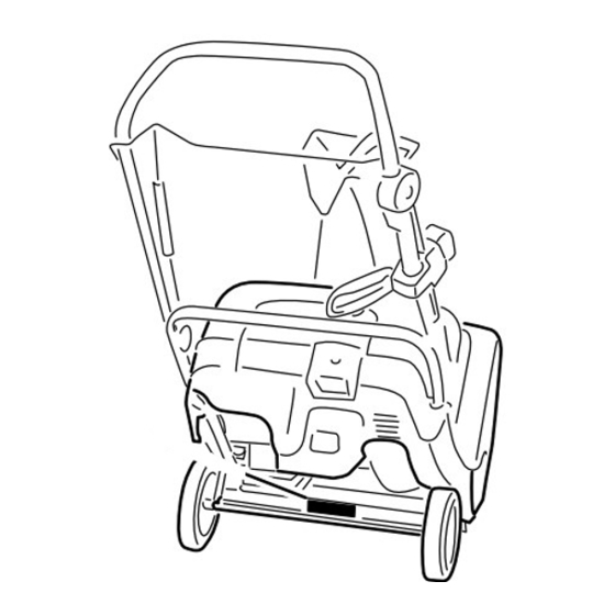
and serial numbers of your product ready. Figure 1
identifies the location of the model and serial numbers
on the product. Write the numbers in the space
provided.
Figure 1
1. Model and serial number location
Model No.
Serial No.
This manual identifies potential hazards and has
safety messages identified by the safety alert symbol
(Figure 2), which signals a hazard that may cause serious
injury or death if you do not follow the recommended
precautions.
© 2008—The Toro® Company
8111 Lyndale Avenue South
Bloomington, MN 55420
1. Safety alert symbol
This manual uses 2 words to highlight information.
Important calls attention to special mechanical
information and Note emphasizes general information
worthy of special attention.
The engine exhaust from this product
contains chemicals known to the State of
California to cause cancer, birth defects,
This spark ignition system complies with Canadian
ICES-002.
The enclosed Engine Owner's Manual is supplied
for information regarding the US Environmental
Protection Agency (EPA) and the California
Emission Control Regulation of emission systems,
maintenance, and warranty. Replacements may be
ordered through the engine manufacturer.
Safety
This snowthrower meets or exceeds the B71.3
specifications of the American National Standards
Institute in effect at the time of production.
Read and understand the contents of this manual
before you start the engine.
This is the safety alert symbol. It is used to alert
you to potential personal injury hazards. Obey all
safety messages that follow this symbol to avoid
possible injury or death.
Improperly using or maintaining this snowthrower
could result in injury or death. To reduce this
Register at www.Toro.com.
Form No. 3358-435 Rev B
Operator's Manual
Figure 2
Warning
CALIFORNIA
Proposition 65 Warning
or other reproductive harm.
Original Instructions (EN)
Printed in the USA
All Rights Reserved
Advertisement
Table of Contents

Related Manuals for Toro Power Clear 38585


Summary of Contents for Toro Power Clear 38585
- Page 1 Whenever you need service, genuine Toro parts, or Warning additional information, contact an Authorized Service Dealer or Toro Customer Service and have the model CALIFORNIA and serial numbers of your product ready. Figure 1 Proposition 65 Warning...
- Page 2 potential, comply with the following safety – If fuel is spilled on clothing, change clothing instructions. immediately. • Use extension cords and receptacles as specified by This snowthrower is capable of amputating hands the manufacturer for all units with electric starting and feet and of throwing objects.
-
Page 3: Clearing A Clogged Discharge Chute
The following list contains safety information specific • Disengage power to the rotor blades when snow to Toro products or other safety information that you thrower is transported or not in use. must know. • Never operate the snow thrower without good •... -
Page 4: Safety And Instructional Decals
Safety and Instructional Decals Important: Safety and instruction decals are located near areas of potential danger. Replace damaged decals. 94-2577 1. To engage the rotor blades, hold the control bar against the handle. 2. To disengage the rotor blades, release the control bar. 114-3753 (Model 38586 only) 1. -
Page 5: Loose Parts
Setup Loose Parts Use the chart below to verify that all parts have been shipped. Procedure Description Qty. – No parts required Unfold the handle. Screws Install the discharge chute. Chute assembly 1. Unfolding the Handle Procedure 1. Loosen the handle knobs, pull out the “U”-shaped handle locks until you can move the handle freely, and rotate the handle to the operating position (Figure 3). -
Page 6: Installing The Discharge Chute
2. Installing the Discharge 1. Move the snowthrower to a level surface. Chute 2. Clean around the oil fill cap (Figure 7). Screws Chute assembly Procedure Install the discharge chute as shown (Figure 6). Figure 7 1. Oil fill cap 3. -
Page 7: Product Overview
Filling the Fuel Tank Product Overview Fill the fuel tank with fresh unleaded gasoline (Figure 9). Figure 8 8. Electric-start button 1. Chute deflector trigger Figure 9 (model 38586 only) 2. Discharge chute 9. Ignition key 1. 1/4 inch (6 mm) 3. -
Page 8: Starting The Engine
oz. (0.62 l), type: SAE 30 detergent oil with an API service classification of SJ, SL, or higher.) 5. Screw the oil fill cap into the oil fill hole and tighten it securely. Starting the Engine 1. Turn the ignition key clockwise to the On position (Figure 11). -
Page 9: Disengaging The Rotor Blades
Figure 16 1. Control bar Figure 15 Disengaging the Rotor Blades Important: Run the electric starter no more than 10 times at intervals of 5 seconds on, then To disengage the rotor blades, release the control bar 5 seconds off. Running the electric starter (Figure 17). -
Page 10: Adjusting Discharge Chute And Chute Deflector
Adjusting the Discharge Chute Preventing Freeze-up after and Chute Deflector • Let the engine run for a few minutes to prevent To adjust the discharge chute, press the trigger of the moving parts from freezing. Stop the engine, wait Quick Shoot™ control on the right hand side of the for all moving parts to stop, and remove ice and handle and move it up or down along the handle. -
Page 11: Recommended Maintenance Schedule(S)
Maintenance Note: Determine the left and right sides of the machine from the normal operating position. Recommended Maintenance Schedule(s) Maintenance Service Maintenance Procedure Interval • Check the control cable and adjust it if necessary. After the first hour • Check for loose fasteners and tighten them if necessary. •... -
Page 12: Inspecting The Rotor Blades
Inspecting the Rotor Blades Note: You can pull up the adjuster link and cable to make unhooking the spring easier. Service Interval: Yearly—Inspect the rotor blades and 2. Move the Z-fitting to a higher or lower hole on the have an Authorized Service Dealer adjuster link as needed to obtain the 1/16-inch to replace the rotor blades and scraper if 1/8-inch (2 mm to 3 mm) gap between the control... -
Page 13: Servicing The Spark Plug
Servicing the Spark Plug 6. Clean around the oil fill cap (Figure 26). Service Interval: Yearly—Service the spark plug and replace it if necessary. Use a Champion RJ19LM spark plug or equivalent. 1. Stop the engine and wait for all moving parts to stop. 2. - Page 14 8. Set the gap on the plug to 0.030 inch (0.76 mm) (Figure 31). Figure 31 1. Center electrode insulator 3. Air gap (not to scale) 2. Side electrode 9. Install the spark plug and tighten the plug securely. 10. Connect the wire to the spark plug. 11.
- Page 15 Figure 34 16. Secure the exhaust baffle using the small side screw that you previously removed (Figure 35). Figure 33 1. Tabs 13. Install the 2 screws into the exhaust baffle. 14. Return the snowthrower to the operating position. 15. Tuck the lower lip of the guard behind the belt cover (Figure 34).
-
Page 16: Replacing The Drive Belt
Replacing the Drive Belt Note: Route the new drive belt first around the engine pulley, then the idler pulley, and finally around If drive belt becomes worn, oil-soaked, excessively the loose rotor pulley positioned just above the rotor cracked, frayed, or otherwise damaged, replace the belt. shaft (Figure 36). - Page 17 Figure 39 1. Cable clamps 2. Position the Quick Shoot control between the two arrows located on the right hand side of the upper handle (Figure 40). Figure 41 4. Hold the discharge chute in the straight-ahead position, pull the lower cable casing downward until you remove the slack in the cable, and tighten the screw on the lower cable clamp securely (Figure 42).
-
Page 18: Storing The Snowthrower
Storage Storing the Snowthrower • Gasoline fumes are highly flammable, explosive, and dangerous if inhaled. If you store the product in an area with an open flame, the gasoline fumes may ignite and cause an explosion. Figure 43 • Do not store the snowthrower in a house 1. - Page 19 14. Tighten any loose fasteners. Repair or replace any damaged parts. 15. Cover the snowthrower and store it in a clean, dry place out of the reach of children. Allow the engine to cool before storing it in any enclosure.
- Page 20 Countries Other than the United States or Canada Customers who have purchased Toro products exported from the United States or Canada should contact their Toro Distributor (Dealer) to obtain guaran- tee policies for your country, province, or state. If for any reason you are dissatisfi ed with your Distributor’s service or have diffi culty obtaining guarantee information, contact the Toro importer.