Table of Contents
Advertisement
Quick Links
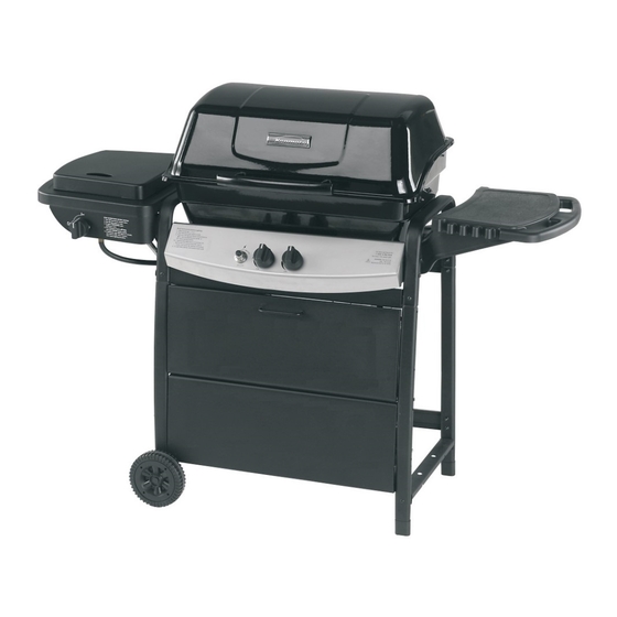
Use and Care Guide
Liquid Propane Gas Grill
Kenmore Model No. 415.16505900
Kmart Item No. 640-175289115
This Grill is for Outdoor Use Only
WARNING
Read and follow all Safety, Assembly,
•
and Use and Care Instructions in this
Guide before assembling and cooking
with this grill.
Failure to follow all instructions in this
•
Use and Care Guide may lead to fire or
explosion, which could result in property
damage, personal injury or death.
Sears, Roebuck and Co., Hoffman Estates, IL 60179 U.S.A.
©2008 Sears, Roebuck and Co., All Rights Reserved
SAVE THESE INSTRUCTIONS!
Safety
•
Parts
•
Use and Care
•
Assembly
•
Assembly Questions?
Call 1-800-241-7548
Tools needed for assembly:
Adjustable wrench (not provided)
Screwdriver (not provided)
7/16" Combination wrench (not provided)
Printed in China
464722309
• 464722509
• 80017881 • 12-13-08
Advertisement
Table of Contents
Troubleshooting

Related Manuals for Kenmore 415.16505900


Summary of Contents for Kenmore 415.16505900
-
Page 1: Save These Instructions
Use and Care Guide Liquid Propane Gas Grill Kenmore Model No. 415.16505900 Kmart Item No. 640-175289115 This Grill is for Outdoor Use Only Safety • WARNING Parts • Use and Care • Read and follow all Safety, Assembly, • Assembly •... -
Page 2: For Your Safety
DANGER WARNING CALIFORNIA PROPOSITION 65 If you smell gas: 1. Combustion by-products produced when using 1. Shut off gas to the appliance. this product contain chemicals known to the State of 2. Extinguish any open flame. California to cause cancer, birth defects, and other 3. -
Page 3: Table Of Contents
Kenmore Elite Grill Warranty ......3 Use and Care ........4-10 Three-Year Limited Warranty on Burners Parts List . -
Page 4: Use And Care
LP Tank USE AND CARE •The LP tank used with your grill must meet the following requirements: DANGER •Use LP tanks only with these required measurements: 12" (30.5cm) (diameter) x 18" (45.7 cm) (tall) with 20 lb. (9 kg.) capacity maximum. •... - Page 5 LP Tank Exchange Connecting Regulator To The LP Tank 1.LP tank must be properly secured onto grill. (Refer to •Many retailers that sell grills offer you the option of replacing your empty LP tank through an exchange service. Use only assembly section.) those reputable exchange companies that inspect, precision fill, 2.Turn all control knobs to the OFF position.
- Page 6 Leak Testing Valves, Hose and Regulator 1.Turn all grill control knobs to OFF. 2.Be sure regulator is tightly connected to LP tank. 3.Completely open LP tank valve by turning OPD hand wheel counterclockwise. If you hear a rushing sound, turn gas off immediately.
- Page 7 Safety Tips WARNING Before opening LP cylinder valve, check the coupling nut for tightness. For Safe Use Of Your Grill And To Avoid Serious When grill is not in use, turn off all control knobs and LP Injury: cylinder valve. •Do not let children operate or play near grill.
- Page 8 Sideburner Match Lighting Main burner Ignitor Lighting Do not lean over grill while lighting. Turn OFF all burner control valves. 1. Open lid during lighting. 2. Open sideburner lid ( if equipped). Turn ON valve from source or tank. Turn on gas at LP cylinder. Push and turn Ignition Burner control knob to HI and 3.Place lit match near burner.
-
Page 9: Ignitor Check
Turning Grill Off CAUTION •Turn all knobs to OFF position. Turn LP tank off by turning OPD hand wheel clockwise to a full stop. Ignitor Check SPIDER ALERT! •Turn gas off at LP tank. Press and hold ignitor button. "Click" should be heard and spark seen each time between collector GAS COLLECTOR box or burner and electrodes. - Page 10 Food Safety Cleaning the Burner Assembly Follow these instructions to clean and/or replace parts of burner Food safety is a very important part of enjoying the outdoor assembly or if you have trouble igniting grill. cooking experience. To keep food safe from harmful bacteria, 1.
-
Page 11: Parts List
PARTS LIST Key Qty Description Part # Key Qty Description Part # UPPER SUPPORT, F/ LEGS 80009811 DRIP PAN, F/ SB 80006246 LEG (W HEEL), LEFT, FRONT, 80009831 SIDEBURNER 80013817 CURVED ELECTRODE W / W IRE, F/ 80017658 LEG (W HEEL), LEFT, BACK, 80009830 SIDEBURNER STRAIGHT... -
Page 12: Parts Diagram
PARTS DIAGRAM 12 • 464722309 • 464722509... -
Page 13: Assembly
ASSEMBLY Left Leg ‘ Place one upper leg as shown . NOTE: Left front and left back legs do not have leg extenders. In front, attach upper leg, side brace and left front leg (curve) with #10-24x1-1/4" screw and #10-24 flange nut. Tighten screws. In back, attach upper leg, side brace and left back leg (straight) with #10-24x1-1/4"... - Page 14 Upper and lower Front Panel and Top brace Lay front legs down on the floor. Fit upper front panel between legs. Attach with 2’’ hinge pins and hitch pins through the 3rd hole down from the top of the leg, and the bottom hole of the top front panel. Attach lower front panel with #10-24x2’’...
- Page 15 Tank Exclusion Hank tank exclusion wires onto lower front panel brackets, attach other ends to back brace with #8-32X3/8’’ sheet metal screws. #8-32X3/8’’ #8-32X3/8’’ Sheet Metal Screw Sheet Metal Screw Qty.2 Loosen screws to adjust upper and lower front panels to line up Tank Exclusion Wire Back Brace...
- Page 16 Control Panel and Firebox Support Stand cart upright. In front, fit control panel between left and right legs. Insert #10-24x2’’ machine screws to hold panel in place. Place upper firebox supports onto screws making sure angle side is facing the front and attach with # 10-24 flange nuts. See the insert for correct placement.
- Page 17 Heat Shield Attach heat shield with #10-24x1/2’’ machine screws and #10-24 flange nuts. Tank Retainer Insert tank retainer into side brace and secure with #10-24x3/8’’ wing screw. Heat shield #10-24x1/2” #10-24 Machine Screw Flange Nut Qty.2 Qty. 2 Transparentize the left firebox support #10-24x3/8’’...
- Page 18 Burner and Firebox and Control Knobs Place burner assembly into firebox. Fasten the burner assembly to the firebox using 5x15 fiber washers and #10-24x1/2’’ machine screws Inside firebox, insert heat diffuser supports with 5x15 fiber washers to firebox through sides of firebox, then secure with #10-24 flange nuts on outside of firebox (A).
- Page 19 Right Side Shelf and Side Burner Support Shelf Attach mounting brackets to Right Side Shelf with #8-32x3/8’’ sheet metal screws and side shelf bushings (A). Note: Do not overtighten the screws. Insert mounting brackets into Side Burner Shelf Support, and secure with #10-24x1/2’’ machine screws (B). Attach Right Side Shelf and Side Burner Support Shelf to front of leg with 1/4’’-20x1/2’’...
- Page 20 Sideburner Attach sideburner valve with #8-32x3/8’’ machine screws. Attach sideburner pan with #8-32x3/8’’ sheet metal screws and 5x9 fiber washers (A). Place sideburner into shelf (B). Make sure valve is inside sideburner tube (C). Attach sideburner with #8-32 wing nut and 5x9 fiber washer (B).
- Page 21 Lower Hinges Attach lower hinges to back of firebox using #10-24x1/2’’ machine screws, 5x15 fiber washers and #10-24 flange nuts. The center flat portion of the hinge should be at the bottom (see inset). #10-24x1/2” Machine Screw Qty.4 Center flat portion of hinge on bottom 5x15 Fiber Washer...
- Page 22 Attach Lid Place lid assembly onto firebox, aligning hinges. Hinges on lid fit inside hinges on firebox. Secure using two hinge pins and hitch pins. Hitch Pin Qty.2 Hinge Pin Qty.2 Heat Diffuser and Cooking Grate Place heat diffuser onto heat diffuser support. Place cooking grate into firebox.
- Page 23 Swing Away Insert ends of Swing Away pivot wire into holes in sides of grill lid. Insert ends of Swing Away leg wire into holes in sides of firebox. NOTE: Pivot and leg wires, running side-to-side, should be under wires running front-to-back. If pivot and leg wires are on top, Swing Away is installed upside-down.
- Page 24 LP Tank Tank collar opening must face to front of grill. Loosen wing nut from tank retainer bracket. Set bottom of tank into notches of tank bracket. Place tank retainer bracket onto tank collar and tighten wing nut. LP CYLINDER IS SOLD SEPARATELY. Fill and leak check the cylinder before attaching to grill and regulator (see Use & Care section).
-
Page 25: Troubleshooting
EMERGENCIES: If a gas leak cannot be stopped, or a fire occurs due to gas leakage, call the fire department. Emergencies Possible Cause Prevention/Solution Gas leaking from •Damaged hose. •Turn off gas at LP cylinder or at source on natural gas systems. If cracked/cut/burned anything but burned, replace valve/hose/regulator. - Page 26 Troubleshooting (continued) Problem Possible Cause Prevention/Solution ELECTRONIC IGNITION: Burner(s) will not light using ignitor. •No spark, no ignition noise. • See Section I of Electronic Ignition System. (See Electronic Ignition Troubleshooting also) •No spark, some ignition noise. • See Section II of Electronic Ignition System. •Sparks, but not at electrode or at full •...
-
Page 27: Troubleshooting
Troubleshooting - Electronic Ignition Problem (Ignition) Possible Cause Check Procedure Prevention/Solution SECTION I No sparks appear at •Battery not installed •Check battery orientation. •Install battery (make sure that “+” and “–” properly. any electrodes when connectors are oriented correctly, with “+” end up control knob turned to and “–”... - Page 28 Get it fixed, at your home or ours! Your Home For expert troubleshooting and home solutions advice: www.managemyhome.com For repair – in your home – of all major brand appliances, lawn and garden equipment, or heating and cooling systems, no matter who made it, no matter who sold it! For the replacement parts, accessories and owner’s manuals that you need to do-it-yourself.