Brother FAX-2820 Service Manual
Facsimile equipment
Hide thumbs
Also See for FAX-2820:
- User manual (161 pages) ,
- Quick setup manual (13 pages) ,
- Quick setup manual (13 pages)
Table of Contents
Advertisement
Quick Links
Download this manual
See also:
User Manual
Advertisement
Table of Contents
Troubleshooting

Related Manuals for Brother FAX-2820


Summary of Contents for Brother FAX-2820
-
Page 1: Service Manual
FACSIMILE EQUIPMENT SERVICE MANUAL MODELS: FAX-2820/2825/2910/2920 MFC-7220/7225N Confidential... - Page 2 © Copyright Brother 2005 All rights reserved. No part of this publication may be reproduced in any form or by any means without permission in writing from the publisher. Specifications are subject to change without notice. Confidential...
-
Page 3: How This Manual Is Organized
PREFACE This Service Manual is intended for use by service personnel and details the specifications, construction, theory of operation, and maintenance for the Brother machines noted on the front cover. It includes information required for troubleshooting and service--disassembly, reassembly, and lubrication--so that service personnel will be able to understand equipment function, repair the equipment in a timely manner and order spare parts as necessary. - Page 4 CHAPTER 8 MAINTENANCE MODE Describes the maintenance mode which is exclusively designed for the purpose of checks, settings and adjustments using the keys on the control panel. In the maintenance mode, you can update memory (EEPROM: electrically erasable programmable read-only memory) for setting the CIS scanner area, for example. You can also customize the EEPROM according to the shipment destination of the machine concerned.
-
Page 5: Table Of Contents
TABLE OF CONTENTS CHAPTER 1 PARTS NAMES & FUNCTIONS EQUIPMENT OUTLINE .................... 1-1 CONTROL PANEL....................1-2 COMPONENTS......................1-5 CHAPTER 2 SPECIFICATIONS GENGERAL ......................2-1 2.1.1 General Specifications..................2-1 2.1.2 Paper Specifications .................... 2-2 2.1.3 Printable Area........................ 2-4 2.1.4 Toner Cartridge Weight Information................2-8 SPECIFICATIONS LIST.................... - Page 6 CHAPTER 5 DISASSEMBLY/REASSEMBLY AND LUBRICATION DISASSEMBLY/REASSEMBLY ................5-1 Safety Precautions ....................... 5-1 Tightening Torque ......................5-2 Preparation ........................5-3 How to Access the Object Component ................ 5-3 Disassembly Flowchart ....................5-4 5.1.1 Paper Eject Tray ....................5-5 5.1.2 Drum/Toner ASSY ....................5-5 5.1.3 Paper Tray ......................
- Page 7 5.1.25 Tail Edge Actuator ..................... 5-55 5.1.26 Regist Front Actuator/Regist Front Spring............5-55 5.1.27 Regist Sensor PCB ASSY ................. 5-56 5.1.28 Regist Rear Actuator/Regist Rear Spring............5-56 5.1.29 Fan Motor 60 Unit ....................5-57 5.1.30 Toner LED PCB ASSY/LED Holder..............5-58 5.1.31 New Toner Actuator/New Toner Actuator Spring ..........
- Page 8 IF YOU REPLACE THE CIS ..................6-4 [ 1 ] Acquire of white level data and set the CIS scanner area setting (Function code 55)..................6-4 IF YOU REPLACE THE LASER UNIT ..............6-4 [ 1 ] Inputting the adjusted value of the laser scanner........6-4 CHAPTER 7 CLEANING CHAPTER 8...
- Page 9 CHAPTER 9 ERROR INDICATION AND TROUBLESHOOTING error indication ......................9-1 9.1.1 Equipment Errors....................9-1 [ 1 ] Error messages appearing on the LCD............9-1 [ 2 ] Error codes shown in "MACHINE ERROR X X" messages ......9-6 9.1.2 Communications Errors ..................9-12 troubleshooting .....................
- Page 10 Please keep these instructions for later reference and read them before attempting any maintenance. NOTE: (For FAX-2820/2825 and MFC-7220/7225N) If there are faxes in the machine's memory, you need to print them or save them before you turn off the power and unplug the machine.
- Page 11 WARNING DO not use any type of spray to clean inside or outside of the machine. Doing this may cause a fire or electrical shock. WARNING IMPORTANT SAFETY INSTRUCTIONS When using your telephone equipment, basic safety precautions should always be followed to reduce the risk of fire, electric shock and injury to people, including the following: 1.
-
Page 12: Choosing A Location
CHOOSING A LOCATION Place your machine on a flat, stable surface that is free of vibration and shocks, such as a desk. Put the machine near a telephone wall jack and a standard, grounded AC power outlet. Choose a location where the temperature remains between 50°F and 90.5°F (10°C and 32.5°C). CAUTION •... -
Page 13: Chapter 1 Parts Names & Functions
CHAPTER PARTS NAMES & FUNCTIONS Confidential... - Page 14 CHAPTER 1 PARTS NAMES & FUNCTIONS This chapter contains external views and names of components and describes their functions. Information about the keys on the control panel is included to help you check operation or make adjustments. CONTENTS EQUIPMENT OUTLINE ....................1-1 CONTROL PANEL......................1-2 COMPONENTS........................1-5 Confidential...
-
Page 15: Equipment Outline
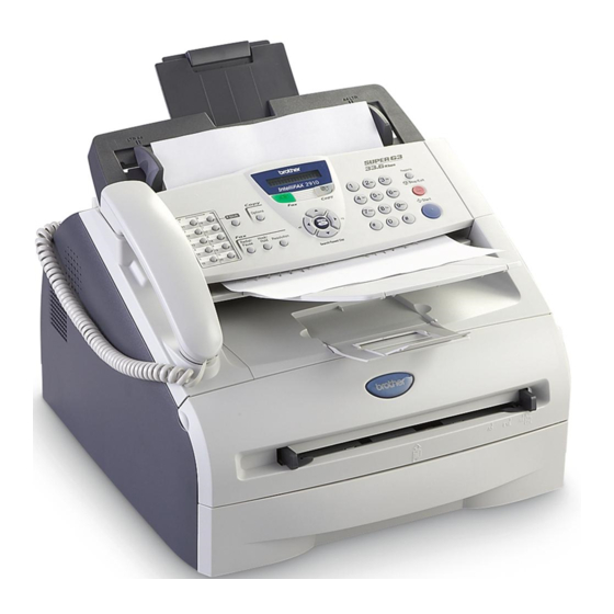
1.1 EQUIPMENT OUTLINE Front view Control Panel Cover ADF Document Support Telephone Handset Automatic Document Feeder (ADF) Control Panel ADF Document Output Support Face-down Output Tray Manual Feed Slot Support Flap with Extension Paper Tray Power Switch Front Cover Rear view USB Interface Connector AC Power Connector Parallel Interface Connector... -
Page 16: Control Panel
1.2 CONTROL PANEL FAX-2820, FAX-2825, FAX-2910 and FAX-2920 have the same keys. MFC-7220 and MFC-7225N have the same keys. 1 - 2 Confidential... - Page 17 Use these keys to dial telephone or fax numbers and as a (MFC-7220 and MFC-7225N) or 20 keyboard for entering information into the machine. (FAX-2820, FAX-2825, FAX-2910 and FAX-2920) The # key lets you temporarily switch the dialing mode previously stored dial numbers.
- Page 18 9. Liquid Crystal Display (LCD) 11. Shift (FAX-2820, FAX-2825, FAX-2910 and FAX-2920 only) Displays messages on the screen to help you set up and To access One-Touch numbers 11 to 20, hold down use your machine. Shift as you press the One-Touch key.
-
Page 19: Components
1.3 COMPONENTS The equipment consists of the following major components: Panel Unit Document Base ASSY Document Chute ASSY Paper Eject Tray Handset Holder NCU PCB & Shield Case Buttery ASSY Inner Chute Cover ASSY Inner Chute Laser Unit Back Cover Side Cover R Rear Chute Cover Fixing Unit... -
Page 20: Chapter 2 Specifications
CHAPTER SPECIFICATIONS Confidential... - Page 21 CHAPTER 2 SPECIFICATIONS This chapter lists the specifications of each model, which enables you to make a comparison of different models. CONTENTS GENERAL........................2-1 2.1.1 General Specifications..................2-1 2.1.2 Paper Specifications .................... 2-2 2.1.3 Printable Area........................ 2-4 2.1.4 Toner Cartridge Weight Information................2-8 SPECIFICATIONS LIST ....................
-
Page 22: General Specifications
2.1 GENERAL 2.1.1 General Specifications Memory Capacity 8 MB (FAX-2820/ FAX-2825) 16 MB (MFC-7220/ FAX-2910/ FAX-2920) 32 MB (MFC-7225N) Automatic Document Feeder (ADF) Up to 20 sheets Paper Tray 250 Sheets (20 lb (80 g/m²)) Printer Type Laser Print Method... -
Page 23: Paper Specifications
2.1.2 Paper Specifications (1) Paper type Manual feed Select the paper type from the Paper type Tray1 slot printer driver Plain paper Plain paper 60 g/m to 105 g/m (16 to 28 lbs.) Recycled paper Recycled paper Bond paper Bond paper Thick paper Thick paper or Thicker paper 105 g/m... - Page 24 (4) Recommended paper Europe Plain paper Xerox Premier 80 g/m Xerox 4200DP 20lb Xerox Business 80 g/m Xerox 4024 28lb Modo Paper DATACOPY 80 g/m Hammermill Laser Paper 24lb IGEPA X-press 80 g/m Recycled paper Xerox Recycled Supreme Xerox Recycled Supreme Transparency 3M CG3300 3M CG 3300...
-
Page 25: Printable Area
2.1.3 Printable Area When using PCL emulation, the edges of the paper that cannot be printed on are shown below. Portrait Physical page Printable area Logical page Physical page length Maximum logical page length Distance from edge of physical page to edge of logical page NOTE: •... - Page 26 The table below shows the printable areas when printing on Portrait for each paper size. Size 215.9 mm 279.4 mm 203.2 mm 279.4 mm 6.35 mm 4.2 mm 8.5” 11.0” 8.0” 11.0” 0.25” 0 mm 0.16” Letter (2,550 dots) (3,300 dots) (2,400 dots) (3,300 dots) (75 dots)
- Page 27 Landscape Physical page Printable area Logical page Physical page length Maximum logical page length Distance from edge of physical page to edge of logical page NOTE: • “Logical page” shows the printable area for a PCL driver. • “Printable area” shows mechanical printable area of the machine. •...
- Page 28 The table below shows the printable areas when printing on Landscape for each paper size. Size 279.4 mm 215.9 mm 269.3 mm 215.9 mm 5.0 mm 4.2 mm 11.0” 8.5” 10.6” 8.5” 0.2” 0 mm 0.16” Letter (3,300 dots) (2,550 dots) (3,180 dots) (2,550 dots) (60 dots)
-
Page 29: Toner Cartridge Weight Information
2.1.4 Toner Cartridge Weight Information Toner Cartridge Weight (approximate weight) TN-2000 EU/ EEU TN-2000 EU/EEU Made in China Made in Malaysia Brand new Toner Cartridge Weight 570g (± 10g) 460g (± 10g) (Recycle: 584g(± 10g)) (Recycle: 474g(± 10g)) Toner Weight at Brand New Toner Cartridge 100g 100g Toner Cartridge Weight at Toner Near Empty... -
Page 30: Specifications List
2.2 SPECIFICATIONS LIST FAX-2820/2825/2920 (1/7) Asia/ Asia/ Europe Europe Canada Pacific Canada Pacific Model Name FAX-2820/2825 FAX-2920 GENERAL Print Engine Laser ( ALL) Laser ( ALL) SparcLite 96MHz SparcLite 96MHz CPU Speed 2hours Yes (up to 4 days) Back up Clock Operating Environment 10 - 32.5 degrees Centigrade... - Page 31 (2/7) Asia/ Asia/ Europe Europe Canada Pacific Canada Pacific Model Name FAX-2820/2825 FAX-2920 GENERAL Approx. Approx. 11.4 kg 11.4 kg Approx. Approx. (Average (Average 10.8 kg Approx. 10.8 kg Weight w/ Carton weight. The weight. The (Approx. 11.3 kg (Approx.
- Page 32 NZ/SIN/HK Den. only) Den. only) only) only) 14.400bps (Fax) 33.600bps (Fax) Modem Speed Approx. 6sec. (Brother #1 & ITU-T #1, Approx. 2sec. (Brother #1 & ITU-T #1, Transmission Speed MMR) JBIG) Super G3 ITU-T Group Coding Method MH / MR / MMR...
- Page 33 400 pages (ITU-T Test Chart, up to 500 pages (ITU-T Test Chart, Standard Resolution, MMR) Standard Resolution, JBIG) Out-of-Paper Reception up to 500 pages ((Brother #1Chart, up to 600 pages ((Brother #1Chart, Standard Resolution, MMR) Standard Resolution, JBIG) Download from Web Site (Send only)
- Page 34 (5/7) Asia/ Asia/ Europe Europe Canada Pacific Canada Pacific Model Name FAX-2820/2825 FAX-2920 Driver Driver Driver PRINTER Download Download Download Less than Less than First Print Out Time Less than 10secs 10secs 10secs Windows Windows Windows GDI Standard Print Language...
- Page 35 TWAIN (WIA for XP) Viewer (PaperPort 9.0) Control Center PC Fax Send : Fax Share (Download (Download Yes (Download from WEB Site) Software by Brother from WEB from WEB Site) Site) PC Fax Receive (Parallel & USB only) Remote Setup...
-
Page 36: Model Name
(7/7) Asia/ Asia/ Europe Europe Canada Pacific Canada Pacific Model Name FAX-2820/2825 FAX-2920 PHOTO CAPTURE Standard NETWORK Share Scanner Share PC FAX (Send) Internet FAX (ITU T.37 simple mode) Scan to E-mail server ITU SUB Addressing Support OS version for PC client... - Page 37 MFC-7220/7225N (1/7) Asia/ Asia/ Europe Europe Canada Pacific Canada Pacific Model Name MFC-7220 MFC-7225N GENERAL Laser ( ALL) Laser ( ALL) Print Engine SparcLite 133MHz SparcLite 133MHz CPU Speed 2hours Yes (up to 4 days) Back up Clock Operating Environment Temperature 10 - 32.5 degrees Centigrade 10 - 32.5 degrees Centigrade 20% - 80% (without condensation)
- Page 38 (2/7) Asia/ Asia/ Europe Europe Canada Pacific Canada Pacific Model Name MFC-7220 MFC-7225N GENERAL Approx. 11.4 kg Approx. Approx. Approx. (Average 10.8 kg 11.3 kg 10.8 kg Weight w/ Carton weight. The (Approx. (Approx. (Approx. specific weight 23.8 lbs.) 23.8 lbs.) 23.8 lbs.) varies country to country)
- Page 39 NZ/SIN/HK Den. only) only) only) 14.400bps (Fax) 33.600bps (Fax) Modem Speed Approx. 6sec. (Brother #1 & ITU-T Approx. 2sec. (Brother #1 & ITU-T #1, Transmission Speed #1, MMR) JBIG) Super G3 ITU-T Group Coding Method MH / MR / MMR...
- Page 40 400 pages (ITU-T Test Chart, up to 500 pages (ITU-T Test Chart, Standard Resolution, MMR) Standard Resolution, JBIG) Out-of-Paper Reception up to 500 pages ((Brother #1Chart, up to 600 pages ((Brother #1Chart, Standard Resolution, MMR) Standard Resolution, JBIG) Yes (Send & Receive) Yes (Send &...
- Page 41 (5/7) Asia/ Asia/ Europe Europe Canada Pacific Canada Pacific Model Name MFC-7220 MFC-7225N PRINTER First Print Out Time Less than 10secs Less than 10secs Windows GDI Windows GDI Standard Print Language PCL6 & BR-Script 3 Emulation Secure Print PCL : Bitmap font:Letter Gothic 16.66, OCR-A, OCR-B, Scalable font: Resident Fonts 49 fonts...
- Page 42 Yes *3 Viewer (PageManager) Yes *2 Yes *2 Control Center PC Fax (Sending only by Brother) PC Fax Receive Remote Setup Yes (for Mac OS X and USB only) Yes (for Mac OS X and USB only) Mac OS 9.1 - 9.2, Mac OS X 10.2.4 Mac OS 9.1 - 9.2, Mac OS X 10.2.4 or...
- Page 43 (Auto IP), WINS/NetBIOS, DNS, LPR/LPD, Custom Raw Port/Port9100, POP3/SMTP, IPP, FTP, mDNS BRAdmin Professional Network Management MIB-II as well as Brother private MIB Optional NETWORK (*6) NC-2100P (Parallel external print NC-2100P (Parallel external print Model Name server) / NC-2200w (Wireless USB...
-
Page 44: Chapter 3 Theory Of Operation
CHAPTER THEORY OF OPERATION Confidential... - Page 45 CHAPTER 3 THEORY OF OPERATION This chapter gives an overview of the scanning and printing mechanisms as well as the sensors, actuators, and control electronics. It aids in understanding the basic principles of operation as well as locating defects for troubleshooting. CONTENTS OVERVIEW ........................3-1 MECHANICAL COMPONENTS..................3-2...
-
Page 46: Overview
3.1 OVERVIEW Host Computer Centronics Control parallel interface USB interface panel interface *1 piece Control Section Printer data Fax data Scanner unit Power Line NCU* Speak Laser printing unit Paper - CIS supplies feeding - ADF motor Charging, exposing, mechanism developing, transferring, and Handset... -
Page 47: Mechanical Components
3.2 MECHANICAL COMPONENTS Polygon motor Halogen heater Laser unit Corona wire Blade Eject roller ASSY Pinch roller Drum/toner ASSY Back cover Paper feed roller Regist front actuator Fixing unit Heat roller Pinch roller Paper eject actuator Separation roller Tail edge actuator Pressure roller Pressure roller Separation pad... -
Page 48: Scanner Mechanism
3.2.1 Scanner Mechanism Document Separation rubber Actuator F Actuator R Document base ASSY LF roller Document ejection roller ASSY Separation roller Paper ejection tray CIS unit Pressure roller Pinch roller 3.2.2 Document Feeding and Ejecting Mechanism This mechanism consists of the document base ASSY, automatic document feeder (ADF), document ejection roller ASSY, and document sensors. -
Page 49: Printing Mechanism
3.2.4 Printing Mechanism 3.2.4.1 Paper supply The feed roller picks up a few sheets or one sheet of paper from the paper tray every time it is rotated and feeds it to the separation roller. Regist front actuator Separation roller Pinch roller Pinch roller Paper feed roller... - Page 50 (1) The paper is gripped between the separation roller and separation pad and separated into individual sheets. The separation roller is connected to the gear 52 P/R. (2) The section of the gear 52 P/R, where there is no cog, is normally fixed at the position as shown in the figure below by the P/R solenoid ASSY.
-
Page 51: Push-Up Function Of Paper Tray
3.2.4.2 Push-up function of paper tray In order to improve the transfer function of the paper tray, the pressure plate in the paper tray is lifted up by the motor. The pressure plate comes down while the recording paper tray is inserted into the machine. When the main motor rotates, it drives through some gears to actuate the gear 45 arm/FR. - Page 52 Link lever Pickup roller holder ASSY Hook B Hook C Paper tray Sector cam Up plate gear Pressure plate Up plate Gear 17 < Table side > Hook C Hook spring Hook A Link lever Gear 13 center P/R Hook B Sector cam Rotated by approx.
-
Page 53: Paper Registration
3.2.4.3 Paper registration After the paper top position is detected by the regist front actuator, the paper, separated into individual sheets by the separation roller, is fed further for a specified time, and the paper top position reaches the paper feed roller so that the paper skew is adjusted. Then, the F/R solenoid is turned off, the paper feed roller starts turning, and the paper is fed to the transfer roller in the drum/toner ASSY. -
Page 54: Paper Eject
3.2.4.4 Paper eject After the printing image on the exposure drum is transferred onto the paper, the paper is fed to the fixing unit to fix unfixed toner onto the paper. Afterwards, the paper is ejected from the fixing unit by the heat roller and the pressure roller in the fixing unit. -
Page 55: Toner Cartridge
3.2.4.6 Toner cartridge Develops the electrostatic latent image on the exposure drum with toner and forms the visible image. Toner life end mode The life of the toner cartridge is starter: 1,500, standard: 2,500 pages at the 5% coverage. In the case of low- duty printing, “Toner Life End”... - Page 56 New toner detection mechanism The printer detects the amount of the remaining toner with the sensor and indicates the timing to replace the toner cartridge by displaying ‘Toner Life End’ on the LCD to the user. The problem such as toner leak or image defect may occur when low-duty printing is continued for a long time. To prevent such a problem, the printer provides the function displaying the ‘Toner Low’...
- Page 57 When the new toner detection switch detects that the toner cartridge is replaced with a new one, the developing bias voltage is initialized at the same time. The toner used for the printer has a property that print density is light first and gradually darker in the course of usage.
-
Page 58: Print Process
3.2.4.7 Print process Charging The drum is charged to approximately 900V by an ion charge which is generated by the primary charger. The charge is generated by ionization of the corona wire, which has a DC bias from the high-voltage power supply applied to it. The flow of the ion charge is controlled by the grid to ensure it is distributed evenly on the drum surface. - Page 59 3. The laser beams reflected by the reflection mirror go straight toward the exposure drum below it, then expose the exposure drum. The area exposed to the laser beam is the image to be printed. The surface potential of the exposed area is reduced, forming the electrostatic image to be printed.
- Page 60 Transfer Transfer process After the drum has been charged and exposed, and has received a developed image, the toner formed is transferred onto the paper by applying a negative charge to the back of the paper. The negative charge applied to the paper causes the positively charged toner to leave the drum, and adhere to the paper.
-
Page 61: Sensors And Actuators
3.2.5 Sensors and Actuators Sensor name Sensor type Location Cover sensor Main frame L Mechanical switch Toner LED PCB (Light emission) Main frame R Photo sensor Toner sensor PCB (Light reception) Main frame L Photo sensor Paper eject sensor Main PCB Photo sensor Regist front sensor Photo sensor... -
Page 62: Control Electronics
3.3 CONTROL ELECTRONICS 3.3.1 Components The following illustration shows the hardware components for this machine. The corresponding connection diagram appears in Appendix Heater Toner LED Fan 40 Parallel PCB 2-pin 2-pin 2-pin AC line Power supply PCB CDCC LAN I/F 12-pin 20-pin NCU1... - Page 63 CHAPTER TRANSFER OF DATA LEFT IN THE MACHINE TO BE SENT FOR REPAIR Confidential...
- Page 64 CHAPTER 4 TRANSFER OF DATA LEFT IN THE MACHINE TO BE SENT FOR REPAIR This chapter describes how to transfer data left in the machine to be sent for repair. The service personnel should instruct end users to follow the transfer procedure given in this chapter if the machine at the user site cannot print received data due to the printing mechanism defective.
-
Page 65: Transferring Received Fax Data
4.1 TRANSFERRING RECEIVED FAX DATA When the machine at the user site requires to be repaired, unplugging the power cord from the wall socket for sending the machine for repair will lose received FAX data if unprinted and left in the machine. - Page 66 Cover page sample End page sample 4 -2 Confidential...
-
Page 67: Chapter 5 Disassembly/Reassembly And Lubrication
CHAPTER DISASSEMBLY/REASSEMBLY AND LUBRICATION Confidential... - Page 68 CHAPTER 5 DISASSEMBLY/REASSEMBLY AND LUBRICATION This chapter details procedures for disassembling and reassembling the machine together with related notes. The disassembly order flow provided enables you to see at a glance the quickest way to get to component(s) involved. At the start of a disassembly job, you check the disassembly order flow that guides you through a shortcut to the object components.
- Page 69 5.1.17 Pickup Roller Holder ASSY ................5-36 5.1.18 Fixing Unit ......................5-40 5.1.19 High-Voltage PS PCB ASSY ................5-45 5.1.20 Main PCB......................5-46 5.1.21 PS PCB Unit/Fan 40 ..................5-48 5.1.22 Laser Unit......................5-52 5.1.23 Sub Chute ASSY ....................5-53 5.1.24 Link Lever ......................
-
Page 70: Disassembly/Reassembly
5.1 DISASSEMBLY/REASSEMBLY Safety Precautions To prevent the creation of secondary problems by mishandling, observe the following precautions during maintenance work. Before starting disassembly/reassembly jobs, unplug the power cord and telephone line. In particular, when having access to the power supply inside the machine, make sure that the power cord is unplugged from the electrical outlet;... -
Page 71: Tightening Torque
Tightening Torque Location of screw Screw type Q'ty Tightening torque N•m (kgf•cm) 0.79 ±0.1 (8 ±1) Document base ASSY Taptite, cup B M4x12 0.79 ±0.1 (8 ±1) Side cover L Taptite, bind B M4x12 0.49 ±0.1 (5 ±1) Speaker hold spring Taptite, cup B M3x8 0.79 ±0.1 (8 ±1) Side cover R... -
Page 72: Preparation
Preparation Prior to proceeding with the disassembly procedure, Unplug the modular jack of the telephone line, the USB cable, if connected (not shown below), and the modular jack of the external telephone set if connected (not shown below). How to Access the Object Component •... -
Page 73: Disassembly Flowchart
Disassembly Flowchart 5.1.4 5.1.5 5.1.13 Standard Operation Disassembly Time / Assembly Time Top Cover Back Cover Rear Chute Cover (Second) 5.1.1 5.1.2 5.1.3 10s / 10s 15s / 30s 5s / 5s Paper Eject Tray 5.1.16 Drum/Toner ASSY Paper Tray 5.1.24 1s / 3s 5s / 5s... -
Page 74: Paper Eject Tray
5.1.1 Paper Eject Tray (1) Remove the paper eject tray Paper eject tray 5.1.2 Drum/Toner ASSY (1) Open the front cover and remove the drum/toner ASSY. Front cover Drum/toner ASSY 5 -5 Confidential... -
Page 75: Paper Tray
5.1.3 Paper Tray (1) Close the front cover and pull out the paper tray. (2) Remove the paper from the paper tray. Front cover Paper tray (3) Remove the separation pad holder ASSY and the separation pad spring. Separation pad holder ASSY Separation pad holder ASSY Screwdriver Hooks... -
Page 76: Back Cover
5.1.4 Back Cover (1) Remove the back cover. NOTE: Remove the “A” section of the back cover while opening the back cover slightly. “A” Boss Main frame R Back cover Back cover Back cover 5 -7 Confidential... -
Page 77: Rear Chute Cover
5.1.5 Rear Chute Cover (1) Remove the rear chute cover. Boss Hook Rear chute cover Paper eject actuator Rear chute cover Rear chute cover (2) Remove the paper eject actuator and the eject actuator spring. Eject actuator spring Paper eject actuator Paper eject actuator Rear chute cover Paper eject actuator... -
Page 78: Document Base Assy
5.1.6 Document Base ASSY (1) Remove the two cup B M4x12 taptite screws to remove the document base ASSY. Document base ASSY Taptite, cup B M4x12 5 -9 Confidential... -
Page 79: Side Cover L
5.1.7 Side Cover L (1) Open the front cover. (2) Remove the two bind B M4x12 taptite screws, and then remove the side cover L. Machine Taptite, bind B M4x12 Front cover Hook Side cover L Taptite, bind B M4x12 Hooks (3) Disconnect the connector of the speaker ASSY. -
Page 80: Handset Holder
5.1.8 Handset Holder (1) Open the panel unit and remove the link stopper. Panel unit Handset holder Link stopper (2) Release the four hooks to remove the handset holder. Hooks Handset holder Panel unit Hooks 5 -1 1 Confidential... -
Page 81: Speaker Assy
5.1.9 Speaker ASSY (1) Remove the cup B M3x8 taptite screw to remove the speaker hold spring and speaker ASSY. Side cover L Speaker ASSY Speaker hold spring Taptite, cup B M3x8 5 -1 2 Confidential... -
Page 82: Side Cover R/Link Stopper
5.1.10 Side Cover R/Link Stopper (1) Remove the two bind B M4x12 taptite screws, and then remove the side cover R. Taptite, bind B M4x12 Side cover R Hook Hook Taptite, bind B M4x12 Hook (2) Remove the link stopper from the top cover. Top cover Link stopper 5 -1 3... -
Page 83: Panel Unit
5.1.11 Panel Unit (1) Disconnect the panel harness. (2) Remove the panel unit. Panel unit Main PCB Connector (3) Remove the cup B M3x6 taptite screw to remove the separation rubber, ADF plate spring and front plate spring. Taptit, cup B M3x6 ADF plate spring Separation rubber Front plate spring... - Page 84 (4) Remove the actuator R from the panel unit. Actuator R Hook Panel unit (5) Remove the three cup B M3x8 taptite screws. (6) Release the four hooks to remove the panel rear cover. Taptite, cup B M3x8 Panel rear cover Hooks Hooks Panel cover...
- Page 85 (7) Remove the actuator F from the panel rear cover. Actuator F Panel rear cover (8) Disconnect the LCD harness. NOTE: • After disconnecting flat cable(s), check that each cable is not damaged at its end or short-circuited. When connecting flat cable(s), do not insert them at an angle. After insertion, check that •...
- Page 86 (9) Release the three hooks to remove the panel PCB ASSY (A). Panel PCB ASSY (A) Hooks Hook (10) Release the two hooks to remove the panel PCB ASSY (B). Panel PCB ASSY (B) Hooks 5 -1 7 Confidential...
- Page 87 (11) Remove the rubber key. Rubber key Boss Panel cover Boss Boss (12) Release the two hooks to remove the back light holder. Back light holder Hook Panel cover Hook 5 -1 8 Confidential...
- Page 88 (13) Remove the back light film. (14) Release the one hook to remove the LCD. Back light film Panel cover Hook 5 -1 9 Confidential...
-
Page 89: Hook Pcb Assy
5.1.12 Hook PCB ASSY (1) Disconnect the connector of the hook PCB ASSY. (2) Release the one hook to remove the hook PCB ASSY. Hook PCB ASSY Hook Main PCB (3) Remove the actuator hook from the hook PCB ASSY. Actuator hook Hook PCB ASSY 5 -2 0... -
Page 90: Top Cover
5.1.13 Top Cover (1) Remove the bind B M4x12 taptite screw, and then remove the rear cover stopper. Taptite, bind B M4x12 Top cover Rear cover stopper Hooks Hook (2) Remove the two bind B M4x12 taptite screws, and the rear chute cover spring. (3) Remove the inner chute. - Page 91 NOTE: Re-assemble the inner chute while pushing onto the pinch roller of the inner chute with the eject roller of the top cover. Eject roller Top cover Pinch roller Pinch roller Inner chute (4) Disconnect the three connectors from the main PCB. Top cover NCU harness CIS harness...
- Page 92 CAUTION: • There is a danger of explosion if the battery is incorrectly replaced. • Use Brother genuine spare part when you replace the battery. • Do not disassemble, recharge or dispose of in fire. Used battery should be disposed of according to local regulations.
- Page 93 (9) Remove the two bind B M4x12 taptite screws and release the two hooks to remove the top cover. Top cover Hooks Hook Taptite, bind B M4x12 Hooks Taptite, bind B M4x12 Hook (10) Remove the paper eject roller ASSY from the top cover. Paper eject roller ASSY Top cover NOTE:...
- Page 94 (11) Remove the one cup S M3x6 taptite screw to remove the LF ground plate. Taptite, cup S M3x6 LF ground plate Top cover (12) Release the two hooks to remove the bushing 5. (13) Remove the document ejection roller ASSY Document ejection roller ASSY Top cover Hooks...
- Page 95 (14) Release the hook to remove the pressure roller ASSY. Pressure roller ASSY Top cover Hook (15) Remove the two pressure rollers from the pressure roller shaft. Pressure roller shaft Pressure roller Pressure roller 5 -2 6 Confidential...
- Page 96 (16) Remove the LF spring from the top cover. LF spring Top cover (17) Release the two hooks to remove the bushing 5. (18) Remove the LF roller. LF roller Top cover Hooks Bushing 5 5 -2 7 Confidential...
- Page 97 (19) Remove the cup B M3x4 taptite screw to remove the scanning drive LF FG harness ASSY. LF FG harness ASSY Taptite, cup B M3x4 (20) Remove the four bind B M4x12 taptite screws. (21) Release the four hooks to remove the document chute ASSY from the inner chute cover ASSY.
- Page 98 (22) Remove the CIS. Hook Document chute ASSY (23) Disconnect the CIS harness. CIS harness Document chute ASSY 5 -2 9 Confidential...
- Page 99 (24) Remove the two CIS springs. CIS spring CIS spring Document chute ASSY (25) Remove the LF roller gear. LF roller gear Document chute ASSY 5 -3 0 Confidential...
- Page 100 (26) Remove the separation roller. Separation roller Document chute ASSY (27) Remove the two cup B M3x8 taptite screws to remove the scanning driver ASSY. Taptite, cup B M3x8 Scanning driver ASSY Document chute ASSY 5 -3 1 Confidential...
-
Page 101: Ncu Pcb Assy
(28) Remove the pan (S/P washer) M3x6 screw to remove the scanning motor F sub ASSY. Hook Scanning driver ASSY Screw, pan (S/P washer) Scanning motor F sub ASSY M3x6 5.1.14 NCU PCB ASSY (1) Remove the one pan (S/P washer) M3.5x6 screw to remove the NCU FG harness ASSY. Screw, pan (S/P washer) M3.5x6 NCU FG harness 5-32... - Page 102 (2) Remove the two bind B M4x12 taptite screws to remove the scanning drive LF FG harness and NCU unit. Taptite, bind B M4x12 NCU unit LF FG harness Inner chute cover ASSY (3) Turn the NCU unit upside down. (4) Remove the two cup S M3x6 taptite screws from the NCU unit to remove the NCU PCB ASSY.
-
Page 103: Paper Stopper L/S
5.1.15 Paper Stopper L/S (1) Remove the paper stopper ASSY from the inner chute cover ASSY. Inner chute cover ASSY Paper stopper ASSY (2) Remove the paper stopper S from the paper stopper L. Paper stopper S Paper stopper L 5 -3 4 Confidential... -
Page 104: Front Cover
5.1.16 Front Cover (1) Release the hook of the drive release cam from the front cover ASSY. Hook Front cover ASSY Drive release cam Front cover ASSY (2) Release the hook “A” on the front cover ASSY from the chute. (3) Slide the front cover ASSY to the direction of the arrow shown in the figure below to remove it. -
Page 105: Pickup Roller Holder Assy
5.1.17 Pickup Roller Holder ASSY (1) Turn the printer upside down. (2) Remove the six bind B M4x12 taptite screws, and then remove the chute base. Taptite, bind B M4x12 (A) Taptite, bind B M4x12 (B) Taptite, bind B M4x12 Taptite, bind B M4x12 Chute base FG harness ASSY 5... - Page 106 NOTE: When re-assembling the chute base, check that the bind B M4x12 taptite screws (A) and (B) shown in the figure above are secured correctly. <How to check> Check that the distance between the floor and the separation roller collar of the pickup roller holder ASSY is 45.5 to 47.5mm by using the plate jig.
- Page 107 (3) Remove the spring extension P/R from the gear 52 P/R. (4) Release the hook and remove the gear 52 P/R. Hook Printer top side (Printer body Upside down) F/R roller shaft ASSY Spring extension P/R Main frame L Gear 52 P/R (5) Remove the bush F/R.
- Page 108 (7) Remove the link lever from the hook of the pickup roller holder ASSY. (8) Remove the pickup roller holder ASSY. Pickup roller holder ASSY Printer top side Chute (Printer body upside down) Pickup roller holder ASSY Hook Link lever NOTE: The pickup roller holder spring is assembled on the bottom of the pickup roller holder ASSY.
-
Page 109: Fixing Unit
5.1.18 Fixing Unit (1) Disconnect the heater harness connector and thermistor harness connector. (2) Remove the two cup B M4x12 taptite screws, and then remove fixing unit. Taptite, cup B M4x12 Fixing unit Taptite, cup B M4x12 Heater harness Thermistor harness NOTE: Be sure not to touch the pressure roller. - Page 110 (5) Remove the two PR arm ASSY and two PR bush from the pressure roller. PR arm ASSY Pressure roller PR bush PR bush PR arm ASSY (6) Release each hook of the springs from the fuser frame and remove the four separate claw ASSYs.
- Page 111 (7) Remove the two pan (S/P washer) M3x8 screws. (8) Remove the heat roller. (9) Remove the halogen heater. Screw, pan (S/P washer) Heat roller M3x8 Halogen heater Screw, pan (S/P washer) M3x8 Fuser frame NOTE: When re-assembling the heat roller, assemble the HR bush onto the fuser frame referring to the figure below.
- Page 112 NOTE: When re-assembling the halogen heater, put the halogen heater onto the fuser frame so that the terminal of the heater harness is at the top, and secure the screws in the order shown in the figure below. Halogen heater Heater harness Fuser frame (10) Remove the HR gear.
- Page 113 (12) Remove the thermistor ASSY harness from the four hooks. (13) Remove the cup B M3x12 taptite screw, and then remove the thermistor ASSY. Thermistor ASSY Hooks Hooks Taptite, cup B M3x12 Fuser frame Thermistor ASSY harness NOTE: When re-assembling the thermistor ASSY to the fuser frame, ensure the direction of the thermistor ASSY is correct referring to the figure below;...
-
Page 114: High-Voltage Ps Pcb Assy
5.1.19 High-Voltage PS PCB ASSY (1) Disconnect the three connectors from the high-voltage PS PCB ASSY. (2) Disconnect the high-voltage PS PCB harness from the main PCB. NOTE: • After disconnecting flat cable(s), check that each cable is not damaged at its end or short-circuited. -
Page 115: Main Pcb
5.1.20 Main PCB < MFC-7225N > (1) Disconnect the eleven connectors from the main PCB. NOTE: • After disconnecting flat cable(s), check that each cable is not damaged at its end or short-circuited. • When connecting flat cable(s), do not insert them at an angle. After insertion, check that the cables are not at an angle. - Page 116 (2) Remove the two pan M3x6 screws. (3) Remove the CDCC PCB from main frame L. (4) Disconnect the CDCC PCB harness. NOTE: • When replacing the main PCB, refer to ‘ADJUSTMENTS AND UPDATING OF SETTINGS, REQUIRED AFTER PARTS REPLACEMENT’ in Chapter •...
-
Page 117: Ps Pcb Unit/Fan 40
5.1.21 PS PCB Unit/Fan 40 (1) Remove the duct film. (2) Remove the pan (S/P washer) M3.5x6 screw and FG harness ASSY 1. Main frame R Duct film Screws, pan (S/P washer) M3.5x6 FG harness ASSY 1 LV shield plate cover (3) Remove the two cup S M3x6, taptite screws and pan (S/P washer) M3.5x6 screw. - Page 118 (5) Remove the LV insulation sheet. LV shield plate LV insulation sheet (6) Remove the pan (S/P washer) M3.5x6 screw, and then remove the ground wire. (7) Remove the bind B M4x12, taptite screw and then remove the AC holder. (8) Remove the two bind B M4x12, taptite screws and then remove the LV shield plate.
-
Page 119: Ps Pcb Unit/Fan 40
(9) Remove the two cup S M3x6 taptite screws. (10) Disconnect the three connectors from the PS PCB unit, and then remove the PS PCB unit. (11) Remove the power supply switch from the LV shield plate. Main frame R LV shield plate Power supply switch Taptite, cup S M3x6... - Page 120 (12) Remove the Fan40. Main frame R Label Fan40 CAUTION: When re-assembling the fan motor 60 unit, make sure to turn the side with a label outwards. 5-51 Confidential...
-
Page 121: Laser Unit
5.1.22 Laser Unit (1) Remove the cup S M3x6, taptite screw (A) and FG harness ASSY 6. (2) Remove the four cup S M3x6, taptite screws (B). (3) Remove the laser unit. Main frame R Taptite, cup S M3x6 (B) FG harness ASSY 6 Taptite, cup S M3x6 (A) Laser unit... -
Page 122: Sub Chute Assy
NOTE: • When replacing the laser unit, replace the barcode label attached on the gear plate calking ASSY with a new one supplied with a new unit. Another barcode label supplied with a new unit is spare. Make sure to throw it out. •... -
Page 123: Link Lever
5.1.24 Link Lever (1) Turn the printer body upside down. (2) Pull the “A” section outwards and remove the link lever. Link lever “A” Printer top side (Printer body upside down) NOTE: When re-assembling the link lever, insert the end of the link lever into the main frame L referring to the figure below. -
Page 124: Tail Edge Actuator
5.1.25 Tail Edge Actuator (1) Remove the tail edge actuator with the tail edge spring. (2) Remove the tail edge spring from the tail edge actuator. Tail edge actuator Tail edge spring Chute Printer top side (Printer body upside down) 5.1.26 Regist Front Actuator/Regist Front Spring (1) Remove the regist front actuator with the regist front spring. -
Page 125: Regist Sensor Pcb Assy
5.1.27 Regist Sensor PCB ASSY (1) Remove the bind B M3x6, taptite screw. (2) Release the harness from the hook and remove the regist sensor PCB ASSY. Taptite, bind B M3x6 Regist sensor PCB ASSY Chute Hooks Printer top side (Printer body upside down) 5.1.28 Regist Rear Actuator/Regist Rear Spring (1) Remove the regist rear spring. -
Page 126: Fan Motor 60 Unit
5.1.29 Fan Motor 60 Unit (1) Remove the three bind B M4x12, taptite screws and three FG harness ASSY 1, 4, 5. (2) Remove the base plate. Taptite, bind B M4x12 FG harness ASSY 4 Base plate FG harness ASSY 1 FG harness ASSY 5 Fan motor 60 unit harness Printer top side... -
Page 127: Toner Led Pcb Assy/Led Holder
5.1.30 Toner LED PCB ASSY/LED Holder (1) Remove the toner LED PCB ASSY from the main frame R. Main frame R Hooks Toner LED PCB ASSY (2) Remove the LED holder from the toner LED PCB ASSY. Hook LED holder Toner LED PCB ASSY Hook 5 -5 8... -
Page 128: New Toner Actuator/New Toner Actuator Spring
5.1.31 New Toner Actuator/New Toner Actuator Spring (1) Remove the new toner actuator spring. (2) Release the hook and remove the new toner actuator from the main frame L. Main frame L New toner actuator spring New toner actuator Hook 5.1.32 New Toner Sensor Harness ASSY (1) Release the two hooks and remove the new toner sensor harness ASSY from the main frame Hook... -
Page 129: Cover Sensor
5.1.33 Cover Sensor (1) Release the two hooks and remove the cover sensor from the main frame L. Hook Cover sensor Hook Cover sensor Main frame L 5.1.34 Toner Sensor PCB ASSY (1) Remove the cup B M3x6, taptite screw, and then remove the toner sensor PCB ASSY. Main frame L Toner sensor PCB ASSY Taptite, cup B M3x6... -
Page 130: Main Motor Assy
5.1.35 Main Motor ASSY (1) Remove the main PCB sheet. (2) Remove the four bind B M4x12, taptite screws, and FG harness ASSY 4, and then remove the main shield plate. Main frame L Taptite, bind B M4x12 Main shield plate Taptite, bind B M4x12 FG harness ASSY 4 Main PCB sheet... -
Page 131: Develop Joint
(5) Remove the three cup S M3x6, taptite screws, and then remove the main motor ASSY. Taptite, cup S M3x6 Taptite, cup S M3x6 Main motor ASSY Gear plate calking ASSY 5.1.36 Develop Joint (1) Remove the develop joint from the gear plate calking ASSY. Develop joint Gear plate calking ASSY 5 -6 2... -
Page 132: P/R Solenoid Assy
5.1.37 P/R Solenoid ASSY (1) Remove the bind B M3x10, taptite screw. (2) Remove the P/R solenoid ASSY, the P/R solenoid lever and the solenoid release spring P/R. Main frame L P/R solenoid lever Solenoid release spring P/R P/R solenoid ASSY Taptite, bind B M3x10 5.1.38 F/R Solenoid ASSY (1) Remove the gear ASSY from the main frame L. - Page 133 NOTE: The gear ASSY contains the small gears. Be careful not to lose them by disassembling the gear ASSY. Gear center F/R Gear 40/54 F/R Gear 45 arm F/R Gear 17 planetary F/R (2) Remove the bind B M3x10, taptite screw. (3) Remove the F/R solenoid ASSY, the F/R solenoid lever and the solenoid release spring F/R.
-
Page 134: Main Frame L
5.1.39 Main Frame L (1) Remove the two bind B M4x12, taptite screws, and then remove the main frame L. Main frame L Chute Taptite, bind B M4x12 Main frame L 5 -6 5 Confidential... -
Page 135: Main Frame R
5.1.40 Main Frame R (1) Remove the three bind B M4x12, taptite screws, and then remove the main frame R. Chute Main frame R Taptite, bind B M4x12 Main frame R 5 -6 6 Confidential... -
Page 136: Harness Routing
5.1.41 Harness Routing 5 -6 7 Confidential... - Page 137 5 -6 8 Confidential...
- Page 138 5 -6 9 Confidential...
- Page 139 5 -7 0 Confidential...
- Page 140 5-71 Confidential...
- Page 141 5 -7 2 Confidential...
- Page 142 5 -7 3 Confidential...
-
Page 143: Lubrication
5.2 LUBRICATION Pendulum gear 22/50 Gear plate calking ASSY DEV drive gear * BG4: KANTO KASEI BG- MU (4 mm dia. Ball) Pickup roller holder ASSY * PG2: PG- 661(W) (2 mm dia. Ball) 5-74 Confidential... - Page 144 LF roller Document ejection roller LF ground plate Document chute * KANTO KANSEI GE-676 (2 mm dia. Ball) 5 -7 5 Confidential...
-
Page 145: Chapter 6 Adjustments And Updating Of Settings, Required After Parts Replacement
CHAPTER ADJUSTMENTS AND UPDATING OF SETTINGS, REQUIRED AFTER PARTS REPLACEMENT Confidential... -
Page 146: If You Replace The Main Pcb
CHAPTER 6 ADJUSTMENTS AND UPDATING OF SETTINGS, REQUIRED AFTER PARTS REPLACEMENT This chapter details adjustments and updating of settings, which are required if main PCB and some other parts have been replaced. CONTENTS IF YOU REPLACE THE MAIN PCB................6-1 [ 1 ] Load update programs/data ................ -
Page 147: If You Replace The Main Pcb
6.1 IF YOU REPLACE THE MAIN PCB NOTE: If you replace the main PCB, also replace the ink absorber box. Using the machine without replacing the ink absorber box may cause an overflow of drained ink from the ink absorber box, thereby staining the machine. [ 1 ] Load update program/data If the main PCB is replaced with a new one, write the update program/data onto the flash... -
Page 148: 9 ] Setting The Serial Number
NOTE: Please refer to the illustration below for the identification and the location of the serial number label. MODEL MANUFACTURED : MFC-7220 BROTHER CORP.(ASIA)LTD. I.T.E. BROTHER BUJI NAN LING FACTORY 1T22 SER. NO. SER.NO. LISTED Gold garden Industry, Nan Ling Village,Buji, Rong Gang, Shenzhen, China. -
Page 149: 10 ] Inputting The Adjusted Value Of The Laser Scanner
[ 10 ] Inputting the adjusted value of the laser scanner (1) Select ‘Adjust Scanner’ from Menu. (See step1 of the left illustration) (2) Look for the laser unit serial label which can be found on the right of the main PCB. -
Page 150: If You Replace The Cis
6.2 IF YOU REPLACE THE CIS [ 1 ] Acquire of white level data and set the CIS scanner area setting (Function code 55) Refer to Chapter 8, Section 8.4.12. 6.3 IF YOU REPLACE THE LASER UNIT [ 1 ] Inputting the adjusted value of the laser scanner (1) Double-click the brmainte.EXE file (maintenance utility) stored in the PC. - Page 151 CHAPTER CLEANING Confidential...
-
Page 152: Chapter 7 Cleaning
CHAPTER 7 CLEANING For the cleaning procedures of the drum unit and toner cartridge, refer to the User's Guide. Confidential... -
Page 153: Chapter 8 Maintenance Mode
CHAPTER MAINTENANCE MODE Confidential... - Page 154 CHAPTER 8 MAINTENANCE MODE This chapter describes the maintenance mode which is exclusively designed for the purpose of checks, settings and adjustments using the keys on the control panel. You can customize the EEPROM according to the shipment destination of the machine concerned.
-
Page 155: Entry Into The Maintenance Mode
8.1 ENTRY INTO THE MAINTENANCE MODE Press the Menu/Set and Start keys. Next press the key four times to make the machine enter the maintenance mode. TIP: FAX models equipped with numerical keypads can enter the maintenance mode in the same way as conventional models;... -
Page 156: List Of Maintenance Mode Functions
8.2 LIST OF MAINTENANCE-MODE FUNCTIONS Maintenance-mode Functions Function Reference Function Section (Page) Code EEPROM Parameter Initialization 8.4.1 (8-5) Printout of Scanning Compensation Data 8.4.2 (8-6) ADF Performance Test 8.4.3 (8-8) Test Pattern 8.4.4 (8-9) Firmware Switch Setting 8.4.5.1 (8-10) Printout of Firmware Switch Data 8.4.5.2 (8-12) Operational Check of LCD 8.4.6 (8-13) -
Page 157: User-Access To The Maintenance Mode
(3) To switch the machine back to the standby state, press the Stop/Exit key. When each of the user-accessible functions is completed, the machine automatically returns to the standby state. Menu/Set key FAX-2820/2825/2910/2920 Stop/Exit key and keys Start key 8 - 3... - Page 158 MFC-7220/7225N Stop/Exit key Menu/Set key Start key and keys 8 -4 Confidential...
-
Page 159: Detailed Description Of Maintenance Mode Functions
8.4 DETAILED DESCRIPTION OF MAINTENANCE-MODE FUNCTIONS 8.4.1 EEPROM Parameter Initialization (Function code 01/91) Function The machine initializes the parameters, user switches, and firmware switches registered in the EEPROM, to the initial values. Entering the function code 01 initializes all of the EEPROM areas, but entering 91 does not initialize some areas, as listed below. -
Page 160: Printout Of Scanning Compensation Data (Function Code 05)
8.4.2 Printout of Scanning Compensation Data (Function code 05) Function The machine prints out the white and black level data for scanning compensation. Operating Procedure Do not start this function merely after powering on the equipment but start it after carrying out a sequence of scanning operation. - Page 161 Scanning Compensation Data List 8 -7 Confidential...
-
Page 162: Adf Performance Test (Function Mode 08)
8.4.3 ADF Performance Test (Function code 08) Function The machine counts the documents fed by the automatic document feeder (ADF) and displays the count on the LCD for checking the ADF performance. Operating Procedure (1) Set documents. (Allowable up to the ADF capacity.) The "DOC. -
Page 163: Test Pattern (Function Mode 09)
8.4.4 Test Pattern (Function code 09) Function This function, much like the copying function, prints out test pattern to allow the service personnel to check for record data missing or print quality. Operating Procedure Press the 0 and 9 keys in this order in the initial stage of the maintenance mode. The figure below shows test pattern. -
Page 164: Firmware Switch Setting And Printout
8.4.5 Firmware Switch Setting and Printout 8.4.5.1 Firmware switch setting (Function code 10) Function The machine incorporates the following firmware switch functions which may be activated with the procedures using the control panel keys and buttons. The firmware switches have been set at the factory in conformity to the communications standards and codes of each country. - Page 165 Firmware Switches (WSW01 through WSW51) Continued WSW No. Function WSW38 V.34 transmission settings WSW39 V.34 transmission speed WSW40 V.34 modem settings WSW41 ON-duration of the scanning light source WSW42 Internet mail settings WSW43 Function setting 21 WSW44 Speeding up scanning-1 WSW45 Speeding up scanning-2 WSW46...
-
Page 166: Printout Of Firmware Switch Data (Function Mode 11)
8.4.5.2 Printout of firmware switch data (Function code 11) Function The machine prints out the setting items and contents specified by the firmware switches. Operating Procedure (1) Press the 1 key twice in the initial stage of the maintenance mode. The "PRINTING"... -
Page 167: Operation Check Of Lcd (Function Mode 12)
8.4.6 Operation Check of LCD (Function code 12) Function This function allows you to check whether the LCD on the control panel works normally. Operating Procedure (1) Press the 1 and 2 keys in this order in the initial stage of the maintenance mode. The LCD shows the screen given at figure below. -
Page 168: Operational Check Of Control Panel Pcb (Function Mode 13)
(3) After the last number key or button is pressed, the machine beeps for one second and returns to the initial stage of the maintenance mode. To terminate this operation, press the Stop/Exit key. The machine returns to the initial stage of the maintenance mode. FAX-2820/2825/2910/2920 MFC-7220/7225N 8 - 1 4 Confidential... -
Page 169: Adjustment Of Handset Volume (Function Code 16)
8.4.8 Adjustment of Handset Volume (Function code 16) Function This function is to adjust the handset volume when it is set to Volume Amplify. (The adjustment is valid only when the Volume Amplify is set, and only “Low High” can be set.) Use this function for U.S.A models as it’s provided for the U.S.A models only. -
Page 170: Sensor Operational Check (Function Mode 32)
8.4.9 Sensor Operational Check (Function code 32) Function This function allows you to check whether the 9 sensors. Operating Procedure (1) Press the 3 and 2 keys in this order in the initial stage of the maintenance mode. The machine beeps 1100 Hz and 400 Hz tones cyclically through the following volumes for testing the speaker. -
Page 171: Received Data Transfer Function (Function Mode 53)
8.4.10 Received Data Transfer Function (Function code 53) Function This function transfers received FAX data to another machine. It is useful when the machine cannot print received data due to the printing mechanism defective. NOTE: The number of files that can be transferred at a time is 99. To transfer 100 files or more, carry out the following procedure more than one time. - Page 172 Cover page sample End page sample 8 -1 8 Confidential...
-
Page 173: Fine Adjustment Of Scan Start/End Positions (Function Mode 54)
8.4.11 Fine Adjustment of Scan Start/End Positions (Function code 54) Function This function is to adjust the scan start/end positions. Operating Procedure (1) Press the 5 and 4 keys in this order in the initial stage of the maintenance mode. The “SCAN START ADJ.”... - Page 174 MAINTENANCE 5 and 4 keys SCAN START ADJ. 2 second later Stop/Exit key Menu/Set key Stop/Exit key Menu/Set key ACCEPTED 1 second later 8 -2 0 Confidential...
-
Page 175: Acquisition Of White Level Data And Cis Scanner Area Setting
8.4.12 Acquisition of White Level Data and CIS Scanner Area Setting (Function code 55) Function This function allows the machine to obtain white level data for the CIS scanner and save it together with the CIS scanner area into the EEPROM on the main PCB. Operating Procedure (1) Press the 5 key twice in the initial stage of the maintenance mode. -
Page 176: Eeprom Customizing (Function Mode 74)
The current customizing code (e.g., 8001 in the case of FAX-2820 U.S.A. model) appears. (2) Enter the desired customizing code (e.g., 0002 in the case of FAX-2820 CANADA model). The newly entered code appears. NOTE: The machine does not work properly when an incorrect code is entered. -
Page 177: Display Of The Equipment's Log Information (Function Mode 80)
8.4.15 Display of the Equipment’s Log Information (Function code 80) Function The equipment may display its log information on the LCD. Operating Procedure (1) Press the 8 and 0 keys in this order in the initial stage of the maintenance mode. The USB serial number appears on the LCD. - Page 178 USB: USB Serial No. DRUM: Drum counter COVERAGE: * Average black coverage TTL_PG: Total number of pages printed COPY: Number of copies made PC PRINT: Number of PC prints made FAX: Number of FAX outputs made TR1_PG: Number of pages picked up from the paper tray MN_PAGE: Number of pages picked up from the manual tray A4+LTR:...
-
Page 179: Machine Error Code Indication (Function Mode 82)
8.4.16 Machine Error Code Indication (Function code 82) Function This function displays an error code of the last error on the LCD. Operating Procedure (1) Press the 8 and 2 keys in this order in the initial stage of the maintenance mode. The LCD shows the "MACHINE ERROR X X."... -
Page 180: Chapter 9 Error Indication And Troubleshooting
CHAPTER ERROR INDICATION AND TROUBLESHOOTING Confidential... - Page 181 CHAPTER 9 ERROR INDICATION AND TROUBLESHOOTING This chapter details error messages and codes that the incorporated self-diagnostic functions display if any error or malfunction occurs. If any error message appears, refer to this chapter to find which components should be checked or replaced. The latter half of this chapter provides sample problems that could occur in the main sections of the machine and related troubleshooting procedures.
-
Page 182: Error Indication
9.1 ERROR INDICATION To help the user or the service personnel promptly locate the cause of a problem (if any), the facsimile equipment incorporates the self-diagnostic functions which display error messages for equipment errors and communications errors. For the communications errors, the equipment also prints out the transmission verification report and the communications list. - Page 183 Receive Mode from Manual to another mode. Unit is too Hot The fixing unit is too hot. (For FAX-2820/2825 and MFC-7220) When you turn off the machine’s Fail to Warm up The fixing unit is too cold. power switch its memory will be cleared.
- Page 184 If the fan is not spinning, you need to save the faxes before you follow the suggestions below. (For FAX-2820/2825 and MFC-7220) When you turn off the machine's power switch its memory will be cleared. If there are faxes you need to save them before following the suggestions below.
- Page 185 ERROR MESSAGE CAUSE ACTION Out of Memory The machine’s memory is full. (Fax sending or copy operation in progress) Press Start to send or copy the scanned pages. —OR— Press Stop/Exit and wait until the other operations in progress have finished and then try again.
- Page 186 ERROR MESSAGE CAUSE ACTION Unable to Init. The machine has a mechanical (For FAX-2820/2825 and MFC-7220) problem. (Initialize) When you turn off the machine's power Unable to Print switch its memory will be cleared. —OR— Unable to Scan Check whether the machine has faxes A foreign object, such as a clip or in its memory.
- Page 187 [ 2 ] Error codes shown in the "MACHINE ERROR X X" message Error Code Symptom Probable Cause Solution (Hex) Eject sensor error. (The The back cover is opened. Close the back cover. paper eject sensor actuator Paper eject sensor actuator Reassemble the paper eject is being push down.) caught on the surrounding...
- Page 188 Error Code Symptom Probable Cause Solution (Hex) Hardware on the main PCB Thermistor defective Replace the fixing unit. turns off the heater forcibly PS PCB unit defective Replace the PS PCB unit. since the thermistor detects Main PCB defective Replace the main PCB. that the fixing unit temperature exceeds the setting one.
- Page 189 Error Code Symptom Probable Cause Solution (Hex) Main motor does not Main PCB defective Replace the main PCB. synchronize with the Main motor defective Replace the main motor. reference clock. ASIC error on the main Main PCB defective Replace the main PCB. PCB.
- Page 190 Error Code Symptom Probable Cause Solution (Hex) No paper tray loaded. No paper tray loaded. Load the paper tray. Foreign materials in the paper Remove foreign materials. tray Tail edge actuator caught on the Reassemble the tail edge surrounding parts. actuator.
- Page 191 Error Code Symptom Probable Cause Solution (Hex) The document rear sensor Document jam Remove the jammed does not come ON during document. document pull-in operation. Actuator R caught on the Reassemble the actuator R. surrounding parts Scanning motor F sub ASSY Replace the scanning motor F defective sub ASSY.
- Page 192 Error Code Symptom Probable Cause Solution (Hex) A/D converter reference Main PCB defective Replace the main PCB. voltage error in document scanning (at Low level) Light emission intensity CIS defective Replace the CIS. error of the LED array in Main PCB defective Replace the main PCB.
-
Page 193: Communications Errors
9.1.2 Communications Errors If a communications error occurs, the facsimile equipment (1) emits an audible alarm (intermittent beeping) for approximately 4 seconds, (2) displays the corresponding error message, and (3) prints out the transmission verification report if the equipment is in sending operation. Definition of error codes on the communications list Calling Code 1... - Page 194 Compatibility [checking the NSF and DIS] Code 1 Code 2 Causes Remote terminal only with V.29 capability in 2400 or 4800 bps transmission. Remote terminal not ready for polling. Remote terminal not equipped with password function or its password switch OFF. Remote terminal not equipped with or not ready for confidential mailbox function.
- Page 195 Command reception [checking the NSF and DIS after transmission of NSS and DCS] Code 1 Code 2 Causes Vertical resolution capability changed after compensation of background color. ID checking Code 1 Code 2 Causes Password plus "lower 4 digits of telephone number" not coincident.
- Page 196 (10) Video signal reception Code 1 Code 2 Causes Error correction sequence not terminated even at the final transmission speed for fallback. Receive buffer empty. (5-second time-out) Receive buffer full during operation except receiving into memory. Decoding error continued on 500 lines. Decoding error continued for 10 seconds.
-
Page 197: Troubleshooting
9.2 TROUBLESHOOTING 9.2.1 Introduction This section gives the service personnel some of the troubleshooting procedures to be followed if an error or malfunction occurs with the facsimile equipment. It is impossible to anticipate all of the possible problems which may occur in future and determine the troubleshooting procedures, so this section covers some sample problems. -
Page 198: Troubleshooting Based On Problem Type
9.2.4 Troubleshooting Based on Problem Type [ 1 ] Paper feeding problems Even if the paper is printed and ejected without any problems such as paper jams, paper feeding problems below may appear. Users can clear these problems by following the ‘User Check’ items for each problem. Even if the same problem occurs again, follow the procedures in the table below. - Page 199 Page skew User Check (1) Check that the paper or other media is loaded into the paper tray correctly and that the paper guides are not too tight or too loose against the paper stack. (2) If using the manual feed slot, check how to load paper into the manual feed slot correctly. (3) The paper tray may be too full.
-
Page 200: 2 ] Software Setting Problems
[ 2 ] Software setting problems The printer may not print the data correctly if there are incorrect software settings. “There was an error writing to LPT1: (or BRUSB) for the printer” error message appears. User Check (1) Check that the printer cable is not damaged or broken. Check also that the cable is connected to the correct interface connectors of both the printer and PC. - Page 201 Although the USB driver is installed, it is unable to find the BRUSB: port. (Windows98/Me only) User Check (1) Re-install the USB driver by following the steps below; Turn the printer off. ii) Double-click the file “Deins USB.exe” in the USB directory of the CD-ROM. iii) Re-boot the PC.
- Page 202 5 m or less. Try to connect the printer and • Product ID: PC with the USB cable directly. 0187 (for FAX-2820/2825) 0188 (for FAX-2920) 0185 (for MFC-7220) 0186 (for MFC-7225N) Vender: Brother International Corporation (or 0x4f9)
-
Page 203: 3 ] Malfunction
[ 3 ] Malfunction When taking countermeasures for malfunctions as described in this section, check connectors for contact failure before measuring the voltage at the specified connector pins. No AC power supplied Possible cause Step Check Result Remedy Supply Is the correct voltage Inform the user that the correct voltage present at the outlet? - Page 204 WARNING: If you analyze malfunctions with the power plug inserted into the power outlet, special caution should be exercised even if the power switch is OFF because it is a single pole switch Main motor failure Possible cause Step Check Result Remedy Failure of...
- Page 205 Insufficient output from high-voltage power supply unit Possible cause Step Check Result Remedy High-voltage Do any of the terminals on Clean the terminals. contact the high-voltage contacts have dirt or contact burns? High-voltage Check the connections of Replace the high-voltage power power supply the connector between the supply PCB.
- Page 206 Is it possible to print the Replace the main PCB. test page with the method? Software bug Does this problem appear Inform the Brother office of the when printing specific data used specific data, printer or printing under a specific condition and system environment? environment.
- Page 207 M-10 Pickup function of paper tray does not work. Possible cause Step Check Result Remedy Link lever Does the link lever work? Remove the cause of non- does not move Isn't the link lever bent? smooth operation of the link smoothly.
- Page 208 M-12 Maximum speed is slow. Possible cause Step Check Result Remedy Two or more Does paper double feeding Replace the separation pad. sheets of the occur? paper in the tray are pulled to feed. Foreign body Is a foreign body caught on Remove a foreign body.
-
Page 209: 4 ] Image Defects
[ 4 ] Image defects 1-1 Light 1-2 Dark 1-3 Completely blank 1-4 All black 1-5 Dirt on the back of paper 1-6 Black vertical streaks 1-6 Black vertical streaks 1-7 Black horizontal stripes 1-8 Black vertical 1-9 White vertical streaks streaks Print out test print out test print out test Print out test print o Print out test print o... - Page 210 Light User Check (1) Check the printer’s environment. Conditions such as humidity, high temperatures, etc. may cause this situation to occur. (2) If the whole page is light, toner save mode may be on. Disable toner save mode within Printer Properties tab of the driver. (3) Try installing a new toner cartridge or drum unit.
- Page 211 Dark User Check (1) Check the paper used meets the recommended paper specifications. (2) Check the printer’s environment. High temperature and high humidity conditions can increase the amount of background shading. (3) Clean the corona wire with the wire cleaner. (4) Try installing a new toner cartridge or drum unit.
- Page 212 Completely blank Ground Possible cause Check Remedy Step Result contacts Developing Are the developing bias Clean the electrodes at bias contact contacts between the printer both sides. failure body and drum unit dirty? Drum unit Are the drum shaft and Clean the shaft and the drum electrode of the electrode.
- Page 213 All black User Check (1) Clean the corona wire of the drum unit. (2) The drum unit may be damaged. Install a new drum unit. Ground Possible cause Check Remedy Step Result contacts Corona failure Is the corona wire dirty? Clean the corona wire with the wire cleaner.
- Page 214 Dirt on the back of paper Possible cause Step Check Result Remedy Fixing unit Is the pressure roller dirty? Clean the pressure roller referring dirty Is any other area in the to the following procedure. printer dirty? Dirt in the Is the transfer roller dirty? Replace the drum unit drum unit...
- Page 215 Black and blurred vertical streaks User Check (1) Clean the corona wire in the drum unit. (2) Check that the wire cleaner is at the home position. (3) Check that the toner cartridge is not empty. (4) The drum unit may be damaged. Install a new drum unit. (5) The toner cartridge may be damaged.
- Page 216 Black and blurred horizontal stripes User Check (1) The drum unit may be damaged. Install a new drum unit. (2) Check the paper used meets the recommended paper specifications. (3) Clean the printer interior and the corona wire in the drum unit. Ground Possible cause Check...
- Page 217 White vertical streaks User Check (1) Try to wipe the scanner window with a soft cloth. (2) The toner cartridge may be damaged. Install a new toner cartridge. (3) Check the printer’s environment. High temperature and high humidity conditions can cause this problem. (4) Damp (wet) paper might be used.
- Page 218 I-11 Faulty registration Possible cause Step Check Result Remedy Excessive Is the paper loaded in the Instruct the user to keep paper paper load paper tray more than 27mm loads below 27mm in depth. high? Print paper Is the specified weight of Recommend to use the specified the recommended paper types of paper.
- Page 219 I-12 Poor fixing Possible cause Step Check Result Remedy Print paper Is thick paper of more than Recommend to use the specified 43lb being used? types of paper. Toner sensor Is the problem solved by 1) Toner is empty. failure replacing the drum unit or 2) The toner sensor is defective.
- Page 220 I-13 Image distortion Possible cause Check Remedy Step Result Laser unit Is the laser unit secured to Secure the unit correctly and installation the frame incorrectly? tighten the screws. (Check if there is any play.) Scanner LD Is the laser diode or the Replace the laser unit.
- Page 221 I-15 White spots User Check (1) If the problem is not solved after printing a few pages, the drum unit may have glue from label stock on the exposure drum surface. Refer to Step 1 in the table below and NOTE in the next page.
- Page 222 NOTE: Clean the drum unit as follows. (1) Remove the toner cartridge from the drum unit. Place the printing samples in front of the drum unit, and find the exact position of the image defect. Drum unit Position of smudge on the drum 75.3mm interval Printing sample...
- Page 223 I-16 Black spots User Check (1) If the problem is not solved after printing a few pages, the drum unit may have glue from label stock on the exposure drum surface. Refer to Step 1 in the table below and NOTE in the previous page.
- Page 224 I-17 Black band Ground Possible cause Check Remedy Step Result contacts Corona failure Is the wire cleaner at its Return the wire cleaner home position? to its home position. Corona dirty Is the corona wire dirty? 1) Clean the corona wire.
- Page 225 I-18 Gray background Possible cause Step Check Result Remedy Print paper Does the paper being used Recommend to use the specified meet the paper types of paper. specification (weight, etc.) Recommend to change to freshly unpacked paper. Is the error indication Toner sensor failure.
- Page 226 I-19 Hollow print User Check (1) Check the paper used meets the recommended paper specifications. (2) Select the ‘Thick paper mode’ in the printer driver, or use thinner paper than you are currently using. (3) Check the printer’s environment, conditions such as high humidity may cause this situation to occur.
- Page 227 I-21 Horizontal lines Possible cause Step Check Result Remedy Paper tray Are the ground contacts on Clean the contacts. contacts the right side of the paper tray connecting correctly? Drum unit Are the high-voltage power Clean the contacts. supply and drum unit contacted correctly? I-22 Light rain...
- Page 228 I-23 Ghost User Check (1) Check the paper used meets the recommended paper specifications. Damp paper, thick media or rough surfaced paper can cause the problem. (2) Check the printer’s environment. High temperature and high humidity conditions can cause the problem. (3) Check that the appropriate media type is selected in the printer driver.
- Page 229 Location of Grounding Contacts • Drum unit (2) Wire cleaner Toner cartridge Drum unit (4) Developer roller (3) Charge (1) Exposure drum (7) Cleaner (5) Grid (6) Transfer roller • Printer body & paper tray (4) Developer roller (3) Charge (5) Grid (7) Cleaner (6) Transfer roller...
-
Page 230: 5 ] Incorrect Printout
[ 5 ] Incorrect printout When the data is not printed correctly as it is seen on the PC screen, follow the procedures below in the event of a specific error. The printer prints unexpectedly or it prints garbage. User Check (1) Check if the printer cable is not too long. - Page 231 Unable to print full pages of a document with the “MEMORY FULL” message. User Check (1) Press the Start key on the control panel to print the data remaining in the printer. (2) Reduce the complexity of your document or reduce the printer resolution. NOTE: This problem may appear if the data is too complex.
-
Page 232: 6 ] Network Problem
1. Make sure that the printer is powered on, is on-line and ready to print. 2. Check to see if there is any LED activity. Brother print servers have two LEDs on the back panel of the printer. The upper side LED shows Link status. The lower side LED shows Activity (Receive/Transmit) status. - Page 233 (5) Make the following selection. Make sure that your print server appears. If it is visible, then the connection is good. Otherwise, go to Step 5. 5. If you have tried 1 to 4 above and it does not work, then reset the print server back to the default factory settings and try from the initial setup again.
- Page 234 (1) From the Apple menu, open the Chooser. (2) Click the Brother Laser (IP) icon, and make sure that your print server name appears in the right frame. If it is visible, then the connection is good. Otherwise, go to Step (4).
- Page 235 If you are having trouble printing on a Windows 95/98/Me, Windows NT 4.0 or later Peer-to-Peer network (NetBIOS), check the following: 1. Make sure that the Brother NetBIOS Port driver is correctly installed and configured according ® ® to the Windows 95/98/Me or Windows NT 4.0 Peer-to-Peer (NetBIOS) chapters.
-
Page 236: Troubleshooting Of The Control Panel
[ 7 ] Troubleshooting of the control panel Nothing is displayed on the LCD. User Check (1) Verify if the power switch is turned off. Possible cause Step Check Result Remedy Connection Main PCB and Fix the connector properly. between main control panel PCB PCB and control are properly... - Page 237 The control panel does not work. User Check (1) No Possible cause Step Check Result Remedy Key sticking Any key on control Clean up the panel cover, or panel is stuck. remove the burrs from panel cover and panel keys. Connection Main PCB and Fix the connection properly.
-
Page 238: Troubleshooting Of Fax Functions
[ 8 ] Troubleshooting of fax functions FAX can't send it. User Check (1) Verify that the telephone cord is securely inserted. Possible cause Check Remedy Step Result Dialing mode Dialing signal (PB or Check the dialing mode setting setting DP) comes out at customer's again. - Page 239 Speed dialing and One-touch dialing can't be used. Possible cause Check Remedy Step Result Speed dialing, A fax transmission can Replace the main PCB. One-touch dialing be made using the key, ten? Dialing mode Dialing signal (PB or Check the dialing mode setting setting DP) comes out normally at customer's again.
- Page 240 FAX can't be received. User Check (1) Verify that the telephone cord is securely inserted. Possible cause Check Remedy Step Result Receive mode Receive mode is set to Set the receive mode to setting automatic receive mode. automatic receive mode. NCU PCB Replacement of NCU Replace the NCU PCB with a...
- Page 241 Speaker is silent during on-hook dialing. Possible cause Check Remedy Step Result Connection Main PCB and speaker Fix the connection properly. between main are properly connected. PCB and speaker Speaker Replacement of speaker Replace the speaker with a solves the problem. normal part.
- Page 242 FAX-2820/2825/2910/2920 MFC-7220/7225N APPENDIX 1. SERIAL NUMBERING SYSTEM This appendix shows the location of serial number labels put on some parts and lists the coding information pertaining to the serial numbers. Confidential...
-
Page 243: Serial Number Label
(1) Serial number label for the machine itself MODEL MANUFACTURED : MFC-7220 BROTHER CORP.(ASIA)LTD. I.T.E. 1T22 BROTHER BUJI NAN LING FACTORY SER. NO. Gold garden Industry, Nan Ling Village,Buji, LISTED Rong Gang, Shenzhen, China. This product complies with FDA performance standards for laser products except for deviations pursuant to Laser Notice No.50, dated July 26,2001. - Page 244 (2) Laser unit serial label LSU MODEL DISTINCTION Y delay X delay FRAME MANUFACTURER SERIAL NUMBER AND MOLD DISTINCTION T1 THE 1st. MOLD INSPECTION MACHINE Y3 THE 3rd. MOLD POLYGON MOTOR DISTINCTION REGARDING X delay and Y delay It indicates required delay amount for writing in each of main (X) and sub (Y) scanning direction Location Laser unit serial label App.
- Page 245 FAX-2820/2825/2910/2920 MFC-7220/7225N APPENDIX 2. FIRMWARE INSTALLATION This appendix provides instructions on how to update firmware stored in the flash ROM on the main PCB or load firmware to a new main PCB from the host PC. No hardware replacement is required for updating.
- Page 246 A2.1 INSTALLING THE UPDATE DATA TO THE MACHINE If you want to update the current program stored in the flash ROM of the main PCB to the newer version or after you replace the main PCB, install the update program onto the flash ROM. The program installation requires a PC/AT-compatible computer (which is capable of running MS-DOS or its compatible OS).
- Page 247 Installing the Update Data onto the Flash ROM of the Machine On a PC running Windows 95 (1) Copy the update data and transfer utility onto the desired same directory of the hard disk. e.g., C:\UPDATE (2) Click the Start button, point to Programs, and then click MS-DOS Prompt to open an MS- DOS window.
- Page 248 If you use USB cable Preparation You need to have the BHL2-Maintenance Printer driver and FILEDG32.exe (provided by Brother Industries) on hand. Save them in an arbitrary folder in your PC. Installing the BHL2-Maintenance Printer driver To identify terminals connected via USB interface, a PC requires the corresponding virtual USB devices to be implemented by driver/software.
- Page 249 (6) The following screen appears, indicating the detection of new hardware device by the system. Click Next to proceed. (7) Select "Search for a suitable driver for my device (recommended)" and click Next. (8) Select "Specify a location" and click Next. Ap p .
- Page 250 (9) Select the folder where the copy of the BHL2-Maintenance Printer driver is located (or click Browse to specify it), then click OK. (This sample screen is captured on the Windows 2000 desktop.) (10) Click Next. (11) To proceed, click Yes. Ap p .
- Page 251 "Found New Hardware Wizard" screen in step (6) appears again. Click Cancel. NOTE: To check that the printer driver is successfully installed, click Start|Settings|Printers to call up the Printers window as shown below and confirm that the Brother BHL2-Maintenance Printer icon is displayed.
- Page 252 Writing the update programs/data onto the flash ROM of the machine After the installation procedure of the printer driver, proceed to the firmware writing operation. If the printer driver has been installed so that you start from writing firmware, unplug the power cord from the electrical outlet.
- Page 253 A2.2 SETTING ID CODES TO MACHINES Brother driver machines are assigned unique ID codes (character strings) at the factory. If you replace the main PCB of the machine, the machine will lose its assigned ID code so that it will not be identified by the connected PC*.
- Page 254 NOTE: Customizing codes customize firmware for individual models, enabling the common firmware to be used for various models. They come with the firmware data provided by Brother Industries. Confidential...
-
Page 255: Operating Procedure
(2) Press the 7 and 4 keys in this order in the initial stage of the maintenance mode. The current customizing code appears (e.g., 8001 in the case of FAX-2820 U.S.A. model). (3) Enter the desired customizing code (e.g., 0002 in the case of FAX-2820 CANADA model). The newly entered code appears. - Page 256 FAX-2820/2825/2910/2920 MFC-7220/7225N APPENDIX 4. FIRMWARE SWITCHES (WSW) This appendix describes the functions of the firmware switches, which can be divided into two groups: one is for customizing preferences designed for the shipping destination (as described Appendix 3) and the other is for modifying preferences that match the machine to the environmental conditions.
- Page 257 WSW No. Function Refer to: WSW01 Dial pulse setting App. 4-3 WSW02 Tone signal setting App. 4-4 WSW03 PABX mode setting App. 4-5 WSW04 TRANSFER facility setting App. 4-6 WSW05 1st dial tone and busy tone detection App. 4-7 WSW06 Redial/Pause key setting and 2nd dial tone detection App.
- Page 258 WSW No. Function Refer to: WSW38 V.34 transmission settings App. 4-42 WSW39 V.34 transmission speed App. 4-43 WSW40 V.34 modem settings App. 4-44 WSW41 ON-duration of the scanning light source App. 4-46 WSW42 Internet mail settings App. 4-47 WSW43 Function setting 21 App.
- Page 259 WSW01 (Dial pulse setting) Selector Function Setting and Specifications No. 1 2 Dial pulse generation mode 10-N No. 3 4 60 ms Break time length in pulse dialing 67 ms 40 ms (for 16 PPS) 64 ms (at 106-ms intervals) No.
- Page 260 Selector 7: Switching between pulse (DP) and tone (PB) dialing, by the function switch This selector determines whether or not the dialing mode can be switched between the pulse (DP) and tone (PB) dialing by using the function switch. Selector 8: Default dialing mode, pulse (DP) or tone (PB) dialing This selector sets the default dialing mode (pulse dialing or tone dialing) which can be changed by the function switch.
- Page 261 WSW03 (PABX* mode setting) Selector Function Setting and Specifications CNG detection when sharing a modular wall socket with a 0: A 1: B telephone No. 2 3 4 0 0 0 : 50 ms 0 0 1 : 210 ms Detection time length of 0 1 0 : 500 ms...
- Page 262 Selectors 6 and 7: Dial tone detection in PABX (Not used.) These selectors activate or deactivate the dial tone detection function which detects a dial tone when a line is connected to the PABX. Setting both of these selectors to "1" activates the dial tone detection function so that the machine starts dialing upon detection of a dial tone when a line is connected.
- Page 263 Selector 4: Dual tone detection sensitivity in ICM recording (Not used.) Setting this selector to "1" increases the tone detection sensitivity in ICM recording. Selectors 5 and 6: Earth time length for earth function (Not used.) These selectors set the short-circuiting time length of the telephone line (La or Lb) to ground. This setting is effective only when the earth function is selected for the R key by using the function switch.
- Page 264 Selectors 1 through 3: 1st dial tone detection These selectors activate or deactivate the 1st dial tone detection function which detects the 1st dial tone issued from the PSTN when a line is connected to the PSTN. Setting all of these selectors to "1" activates the dial tone detection function so that the machine starts dialing upon detection of a dial tone when a line is connected.
- Page 265 WSW06 (Redial/Pause key setting and 2nd dial tone detection) Selector Function Setting and Specifications No. 1 2 3 0 0 0 : No pause 0 0 1 : 3.5 sec. WAIT 0 1 0 : 7 sec. WAIT 0 1 1 : 10.5 sec.
- Page 266 Selectors 1 through 3: Redial/Pause key setting and 2nd dial tone detection Selectors No WAIT is inserted even if the Redial/Pause key is pressed. If you press the Redial/Pause key during dialing, the machine will insert WAIT as defined in the above table. If the Redial/Pause key is pressed repeatedly, the machine inserts the specified WAIT multiplied by the number of depressions.
- Page 267 WSW07 (Dial tone setting 1) Selector Function Setting and Specifications No. 1 2 : Narrows by 10 Hz Dial tone frequency band control : Initial value : Widens by 10 Hz Line current detection 0: No 1: Yes (Not used.) No.
- Page 268 WSW08 (Dial tone setting 2) Selector Function Setting and Specifications No. 1 2 3 0 0 0 : 50 ms 0 0 1 : 210 ms 0 1 0 : 500 ms 1st dial tone detection time 0 1 1 : 800 ms length 1 0 0 :...
- Page 269 WSW09 (Protocol definition 1) Selector Function Setting and Specifications Frame length selection 256 octets 1: 64 octets Use of non-standard Allowed 1: Prohibited commands No. 3 4 times No. of retries 3 times 2 times 1 time T5 timer 0: 300 sec. 60 sec.
- Page 270 WSW10 (Protocol definition 2) Selector Function Setting and Specifications Not used. Time length from transmission of the last dial digit to CML 0: 100 ms 1: 50 ms Time length from CML ON to 0: 2 sec. 1: 4 sec. CNG transmission Time length from CML ON to CED transmission (except for...
- Page 271 WSW11 (Busy tone setting) Selector Function Setting and Specifications No. 1 : Narrows by 10 Hz Busy tone frequency band control : Initial value : Widens by 10 Hz 1: 250-750/250-750 ms 1: 400-600/400-600 ms ON/OFF time length ranges 1: 175-440/175-440 ms for busy tone (More than one setting 1: 100-1000 ms/17-660 ms...
- Page 272 WSW12 (Signal detection condition setting) Selector Function Setting and Specifications No. 1 1500 ms Min. detection period required 500 ms for interpreting incoming calling signal (CI) as OFF 700 ms 900 ms No. 3 6 sec. Max. detection period for incoming calling signal (CI) 7 sec.
- Page 273 WSW13 (Modem setting) Selector Function Setting and Specifications No. 1 0 km Cable equalizer 1.8 km 3.6 km 5.6 km No. 3 -43 dBm Reception level -47 dBm -49 dBm -51 dBm 0: 0 dB 1: 8 dB 0: 0 dB 1: 4 dB Modem attenuator 0: 0 dB...
- Page 274 WSW14 (AUTO ANS facility setting) Selector Function Setting and Specifications No. 1 13 Hz Frequency band selection (lower limit) for incoming calling signal 15 Hz (CI) 23 Hz 20 Hz No. 3 30 Hz Frequency band selection (upper limit) for incoming calling signal 55 Hz (CI) 70 Hz...
- Page 275 WSW15 (REDIAL facility setting) Selector Function Setting and Specifications No. 1 5 minutes Redial interval 1 minute 2 minutes 3 minutes No. 3 16 times 1 times No. of redialings 2 times 3 times 15 times Not used. CRP option 0: Disable 1: Enable Selectors 1 through 6:...
- Page 276 WSW16 (Function setting 1) Selector Function Setting and Specifications Not used. ITU-T (CCITT) superfine 0: OFF 1: ON recommendation Not used. Max. document length 0: 400 cm 1: 90 cm limitation Stop/Exit key pressed during 0: Not functional 1: Functional reception NOTE: Selector 7 is applicable to models equipped with ADF units.
- Page 277 WSW17 (Function setting 2 Selector Function Setting and Specifications No. 1 No alarm Always valid Off-hook alarm Valid except when 'call reservation' is selected. Not used. Calendar clock type U.S.A. type 1: European type Not used. Non-ring reception 1: ON Not used.
- Page 278 WSW18 (Function setting 3) Selector Function Setting and Specifications Not used. No. 2 40 sec. Detection enabled time for CNG 0 sec. (No detection) and no tone 5 sec. 80 sec. Not used. Registration of station ID Permitted Prohibited No. 7 No monitoring Up to phase B at the Tone sound monitoring...
- Page 279 WSW19 (Transmission speed setting) Selector Function Setting and Specifications No. 1 First transmission speed choice No. 4 for fallback 2,400 bps 4,800 bps 7,200 bps 9,600 bps 12,000 bps Last transmission speed choice for fallback 14,400 bps V.34 mode 0: Permitted 1: Prohibited V.17 mode 0: Permitted...
- Page 280 WSW20 (Overseas communications mode setting) Selector Function Setting and Specifications EP* tone prefix 0: OFF 1: ON Overseas communications 0: 2100 Hz 1: 1100 Hz mode (Reception) Overseas communications 0: OFF 1: Ignores DIS once. mode (Transmission) No. 4 100 ms Min.
- Page 281 Selectors 8: Limitation on CNG detection If this selector is set to "1," the machine detects a CNG signal according to the condition preset by selectors 2 and 3 on WSW18 after a line is connected. If it is set to "0," the machine detects a CNG signal as long as the line is connected.
- Page 282 WSW22 (ECM and call waiting caller ID) Selector Function Setting and Specifications ECM* in sending 0: ON 1: OFF ECM* in receiving 0: ON 1: OFF Call Waiting Caller ID 0: ON 1: OFF Not used. 0: 0% 1: 8% Acceptable TCF bit error rate (%) 0: 0% 1: 4%...
- Page 283 WSW23 (Communications setting) Selector Function Setting and Specifications 0: From the head of a series of zeros Starting point of training check (TCF) 1: From any arbitrary point No. 2 Allowable training error rate 0.5% No. 4 Decoding error rate for transmission of RTN Not used.
- Page 284 WSW24 (TAD setting 2) Selector Function Setting and Specifications 15 sec. Maximum OGM recording 20 sec. time (Not used.) 30 sec. 50 sec. 4 sec. Time length from CML ON to start of pseudo ring 3 sec. backtone transmission 2 sec. 1 sec.
- Page 285 WSW25 (TAD setting 3) Selector Function Setting and Specifications Not used. No. 5 2 sec. 4 sec. 6 sec. Pause between paging number 8 sec. and PIN 10 sec. 12 sec. 14 sec. 16 sec. Not used. NOTE: Selectors 5 through 7 are applicable to the U.S.A. models only. Selectors 5 through 7: Pause between paging number and PIN These selectors set the pause time between a telephone number being paged and PIN (personal...
- Page 286 WSW26 (Function setting 4) Selector Function Setting and Specifications Not used. Dialing during document reading into the temporary 0: Disable 1: Enable memory in in-memory message transmission No. of CNG cycles to be No. 4 detected (when the line is connected via the external telephone except in the external TAD mode or via the built-in telephone)
- Page 287 WSW27 (Function setting 5) Selector Function Setting and Specifications Not used. Ringer OFF setting 0: Yes 1: No Automatic playback of OGM when switched to the TAD mode 0: No 1: Yes (Not used.) Detection of distinctive ringing 0: Yes 1: No pattern (Not used.)
- Page 288 WSW28 (Function setting 6) Selector Function Setting and Specifications No. 1 2 3 0 0 0 0 dB 0 0 1 +1 dB 0 1 0 +2 dB Transmission level of DTMF 0 1 1 +3 dB high-band frequency signal 1 0 0 0 dB 1 0 1...
- Page 289 WSW29 (Function setting 7) Selector Function Setting and Specifications No. 1 2 3 0 0 0 -47.0 dBm (A) 0 0 1 -48.5 dBm (B) Compression threshold level 0 1 0 -50.0 dBm (C) for voice signals inputted via 0 1 1 -51.5 dBm (D) the telephone line in the built- 1 0 0...
- Page 290 WSW30 (Function setting 8) Selector Function Setting and Specifications No. 1 2 3 0 0 0 -38.0 dBm (A) 0 0 1 -39.5 dBm (B) 0 1 0 -41.0 dBm (C) Dial tone/busy tone detection level during recording of ICM 0 1 1 -42.5 dBm (D) (Not used.)
- Page 291 WSW31 (Function setting 9) Selector Function Setting and Specifications Not used. Default reduction rate for failure of automatic reduction 0: 100% 1: 70% during recording Not used. (Do not disturb this selector.) Minimum ON and OFF duration of ringer signals 0: 130 ms 1: 90 ms effective in distinctive ringing...
- Page 292 WSW32 (Function setting 10) Selector Function Setting and Specifications Not used. No. 5 Standard Default resolution Fine Super fine Photo No. 7 Automatic Default contrast Super light Super dark Selectors 5 and 6: Default resolution These selectors set the default resolution which applies when the machine is turned on or completes a transaction.
- Page 293 WSW33 (Function setting 11) Selector Function Setting and Specifications No. 1 2 3 0 0 0 : -42.5 dBm (A) 0 0 1 : -44.0 dBm (B) 0 1 0 : -45.5 dBm (C) Detection threshold level of "no tone" during recording of ICM 0 1 1 : -47.0 dBm (D) (Not used.)
- Page 294 WSW34 (Function setting 12) Selector Function Setting and Specifications No. 1 0 sec. Erasing time length of ICM 1 sec. tone recorded preceding the 2 sec. tone detection starting point in 3 sec. the case of automatic line 4 sec. disconnection due to no voice 5 sec.
- Page 295 WSW35 (Function setting 13) Selector Function Setting and Specifications No. 1 2 3 4 0 0 0 0 : No detection 0 0 0 1 : 1 sec. Max. detection period of dial tone/busy tone during recording of 0 0 1 0 : 2 sec.
- Page 296 WSW36 (Function setting 14) Selector Function Setting and Specifications ECP mode* 0: ON Recovery from Inactive PC 0: Disable Enable Interface PC Power-off Recognition 0: Normal Long Time Not used. Escape from phase C 0: Yes No. 6 7 8 0 0 0 : 0 (Ignored) 0 0 1 :...
- Page 297 Selectors 6 through 8: Extension of incoming calling signal (CI) frequency band specified by selectors 1 through 4 on WSW14 At the start of reception, if the machine detects the frequency of a CI signal specified by selectors 1 through 4 on WSW14, it starts the ringer sounding. However, the machine may fail to detect the CI signal normally due to noise superimposed at the time of reception.
- Page 298 WSW38 (V.34 transmission settings) Selector Function Setting and Specifications No. 1 X : Automatic Setting of the equalizer : Fixed to 4 points : Fixed to 16 points Sending level of guard tone at 0: Normal - 7 db 1: Normal phase 2 Stepping down the transmission 0: 2400 bps...
- Page 299 WSW39 (V.34 transmission speed) Selector Function Setting and Specifications No. 1 No. 5 2400 bps 4800 bps 7200 bps First transmission speed choice for fallback 9600 bps 12000 bps 14400 bps 16800 bps 19200 bps 21600 bps 24000 bps 26400 bps 28800 bps Last transmission speed choice for fallback...
- Page 300 WSW40 (V.34 modem settings) Selector Function Setting and Specifications Not used. Not masking Masking No. 3 3429 symbols/sec No. 4 3200 symbols/sec Masking of symbol rate(s) No. 5 3000 symbols/sec No. 6 2800 symbols/sec No. 7 Not used. No. 8 2400 symbols/sec NOTE: WSW40 takes effect only when the V.34 mode is permitted (WSW19, selector 7) in models supporting V.34 mode.
- Page 301 Symbol rate Transmission speed Symbol rate Transmission speed Symbol rate Transmission speed (bps) (bps) (bps) 2400 2400 3000 4800 3429 4800 4800 7200 7200 7200 9600 9600 9600 12000 12000 12000 14400 14400 14400 16800 16800 16800 19200 19200 19200 21600 21600 21600...
- Page 302 WSW41 (ON-duration of the scanning light source) Selector Function Setting and Specifications No. 1 2 3 0 0 0 16 hours 0 0 1 24 hours ON-duration of the scanning 0 1 0 12 hours light source at room 0 1 1 8 hours temperature 1 0 0...
- Page 303 WSW42 (Internet mail settings) Selector Function Setting and Specifications Access to the incoming mail (POP3) server 0: Disable 1: Enable (Periodical or on-demand) Access to the outgoing mail 0: Disable 1: Enable (SMTP) server I-FAX relay 0: Disable 1: Enable Coding method J big 0: Disable 1: Enable...
- Page 304 WSW44 ( Speeding up scanning-1) Selector Function Setting and Specifications Not used. No. 6 7 8 0 0 0 : Obtained compensation data ineffective 0 0 1 : 1 min. Effective time length of the white level compensation data 0 1 0 : 3 min.
- Page 305 WSW45 ( Speeding up scanning-2) Selector Function Setting and Specifications No. 1 2 3 0 0 0 : No automatic drawing-in 0 0 1 : 1 sec. Delay time from when 0 1 0 : 2 sec. documents are set until the 0 1 1 : 3 sec.
- Page 306 WSW46 (Monitor of power ON/OFF state and parallel port kept at high) Selector Function Setting and Specifications No. 1 2 0 0 : Disable Monitoring the PC ON/OFF 0 1 : Monitor SELECT IN state 1 0 : Monitor STROBE 1 1 : Monitor both SELECT IN and STROBE...
- Page 307 WSW47 (Switching between high- and full-speed USB) Selector Function Setting and Specifications Handling paper at the 0: Eject paper w/o print 1: Print on the current occurrence of a paper feed paper timing error (Not used.) Not used. No. 3 4 Delay of FAX line 0 0 : 200 ms disconnection when switching...
- Page 308 WSW48 (USB setup latency) Selector Function Setting and Specifications Not used. No. 3 4 5 Entry number Total entry number) 0 0 0 : 25 (100) 0 0 1 : 50 (200) 0 1 0 : 15 (300) Entry number of network PC 0 1 1 : 100 (400) scanner...
- Page 309 WSW49 (End-of-copying beep and print in black) Selector Function Setting and Specifications SIZE: None RAM DISK End-of-copying beep 0: Yes 1: No No. 4 5 0 0 : 150 ms Command flag detection 0 1 : 350 ms time 1 0 : 550 ms 1 1 : 750 ms Not used.
- Page 310 WSW50 (SDAA settings) Selector Function Setting and Specifications No. 1 2 Percentage voltage for 0 0 : 80% interpreting the external telephone as being hooked up 0 1 : 90% (based on the network's 1 0 : 70% standard voltage) (Not used.) 1 1 : No detection Apply the initial value specified by local DC mask curve table to be...
- Page 311 WSW51 (Function setting 16) Selector Function Setting and Specifications Output of communications error 0: Enable 1: Disable report when transmission verification report is disabled Not used. App. 4-55 Confidential...
- Page 312 FAX-2820/2825/2910/2920 MFC-7220/7225N APPENDIX 5. WIRING DIAGRAM This appendix provides the wiring diagram that helps you understand the connections between PCBs. Confidential...
- Page 313 CN19-2 CN10-2 CN501 NFC7225N only PNEW_SEN CN2-12 RL2/POL LINE TELOFF CN12 Hand TELSL TELRL CN2-4 RL2/POL GIJI/ADLC CHRG RDPS CN7-2 SEN_HOOK Confidential...
- Page 314 FAX-2820/2825/2910/2920 MFC-7220/7225N APPENDIX 6. CIRCUIT DIAGRAMS This appendix provides the circuit diagrams of the NCU PCB and power supply PCB. A. NCU PCB (U.S.A. and CANADA models) NCU PCB (EUROPE models) B. Power Supply PCB 100V (U.S.A. and CANADA models)
- Page 315 6 6 6 6 +24V 1SS120 R7 100 2W C103 C2.2 R41-4910-A A5X-24E-908 @R8 620 RA-351M-V6-2 2.7k BT-27 (LINE) C221 C104 4.3k R14 100k C101 C104 RA-242M-C6 C102 RA-242M-C6 11 TELRL TELRL 100k C104 10 TELSL TELSL BA10358 9 +24V TLP421 +24V 100k...
- Page 316 6 6 6 6 +24V @SW1 @C29 C153 1SS120 @C28 @CR1 C153 R41-4910-C @C22 C823 RA-242M-C6 1/4W BT-10 C2.2 @R18 1.6k 1SS120 @C19 @CR2 C561 @C14 S1ZB60 C183 @R17 @R13 68k 3.3k @SW2 ERA15-04 100k @PH1 BA10358 C101 C104 TLP421 100k TLP627 CHRG...
- Page 319 FAX-2820/2825/2910/2920 MFC-7220/7225N APPENDIX 7. LOCATION TO ATTACH THE CAUTION LABEL S Confidential...
- Page 320 LOCATION TO ATTACH THE CAUTION LABEL S CAUTION LABEL S 30x30 Caution label S 30x30 CAUTION LABEL S 13x40 Caution label S 13x40 Confidential App. 7-1...
- Page 321 February '05 SM-FAX037 (13) 8X5A01 Printed in Japan...