Sharp R-21LTF Service Manual
Light duty commercial microwave oven
Hide thumbs
Also See for R-21LTF:
- Operation manual (24 pages) ,
- Specification sheet (2 pages) ,
- Operation manual (24 pages)
Table of Contents
Advertisement
1000W / R -21 LT
PRECAUTIONS TO BE OBSERVED BEFORE AND
DURING SERVICING TO AVOID POSSIBLE EXPO-
SURE TO EXCESSIVE MICROWAVE ENERGY
BEFORE SERVICING
CHAPTER 1. WARNING TO SERVICE PERSONNEL
CHAPTER 2. MICROWAVE MEASUREMENT PRO-
CEDURE
CHAPTER 3. FOREWORD AND WARNING
CHAPTER 4. PRODUCT DESCRIPTION
CHAPTER 5. GENERAL INFORMATION
CHAPTER 6. OPERATION
SHARP CORPORATION
SERVICE MANUAL
LIGHT DUTY COMMERCIAL
MODELS
In the interest of user-safety the oven should be restored to its original
condition and only parts identical to those specified should be used.
WARNING TO SERVICE PERSONNEL: Microwave ovens contain
circuitry capable of producing very high voltage and current, con-
tact with following parts may result in a severe, possibly fatal,
electrical shock. (High Voltage Capacitor, High Voltage Power
Transformer, Magnetron, High Voltage Rectifier Assembly, High
Voltage Harness etc..)
CONTENTS
CHAPTER 7. TROUBLESHOOTING GUIDE
CHAPTER 8. TEST PROCEDURES
CHAPTER 9. TOUCH CONTROL PANEL ASSEMBLY
CHAPTER 10. PRECAUTIONS FOR USING LEAD-
FREE SOLDER
CHAPTER 11. COMPONENT REPLACEMENT AND
ADJUSTMENT PROCEDURE
CHAPTER 12. CIRCUIT DIAGRAMS
Parts List
S7606R21LTFP/
MICROWAVE OVEN
R-21LTF
R-21LVF
This document has been published to be used
for after sales service only.
The contents are subject to change without notice.
R21LTF
Advertisement
Table of Contents

Related Manuals for Sharp R-21LTF


Summary of Contents for Sharp R-21LTF
-
Page 1: Microwave Oven
R21LTF SERVICE MANUAL S7606R21LTFP/ LIGHT DUTY COMMERCIAL MICROWAVE OVEN R-21LTF MODELS 1000W / R -21 LT R-21LVF In the interest of user-safety the oven should be restored to its original condition and only parts identical to those specified should be used. -
Page 2: Table Of Contents
CONTENTS PRECAUTIONS TO BE OBSERVED BEFORE AND [14] Procedure M: FOIL PATTERN ON THE DURING SERVICING TO AVOID POSSIBLE EXPO- PRINTED WIRING BOARD TEST....8-6 SURE TO EXCESSIVE MICROWAVE ENERGY CHAPTER 9. TOUCH CONTROL PANEL ASSEM- CHAPTER 1. WARNING TO SERVICE PERSONNEL Before Servicing .........1-1 OUTLINE OF TOUCH CONTROL PANEL .. -
Page 3: Precautions To Be Observed Before And During Servicing To Avoid Possible Expo
Before servicing an operative unit, perform a microwave emission check as per the Microwave Measurement Procedure outlined in this service manual. If microwave emissions level is in excess of the specified limit, contact SHARP ELECTRONICS CORPORATION immediately @1-800-237-4277. If the unit operates with the door open, service person should 1) tell the user not to operate the oven and 2) contact SHARP ELECTRONICS CORPORATION and Food and Drug Administration's Center for Devices and Radiological Health immediately. -
Page 4: Before Servicing
R21LTF CHAPTER 1. R21LTF WARNING TO SERVICE PERSONNEL Service Manual Microwave ovens contain circuitry capable of producing very high voltage and current, contact with following parts may result in a severe, possibly fatal, electrical shock. (Example) High Voltage Capacitor, High Voltage Power Transformer, Magnetron, High Voltage Rectifier Assembly, High Voltage Harness etc.. Read the Service Manual carefully and follow all instructions. -
Page 5: Cedure 1] Requirements:
R21LTF CHAPTER 2. R21LTF MICROWAVE MEASUREMENT PROCEDURE Service Manual [1] Requirements: 1. Microwave leakage limit (Power density limit): The power density of microwave radiation emitted by a microwave oven should not exceed 1mW/ at any point 5cm or more from the external surface of the oven, measured prior to acquisition by a purchaser, and thereafter (through the use- ful life of the oven), 5 mW/cm at any point 5cm or more from the external surface of the oven. -
Page 6: Chapter 3. Foreword And Warning
Service Manual [1] FOREWORD This Manual has been prepared to provide Sharp Electronics Corp. Service Personnel with Operation and Service Information for the SHARP MICROWAVE OVEN, R-21LTF and R-21LVF. It is recommended that service personnel carefully study the entire text of this manual so that they will be qualified to render satisfactory customer service. -
Page 7: Chapter 4. Product Description
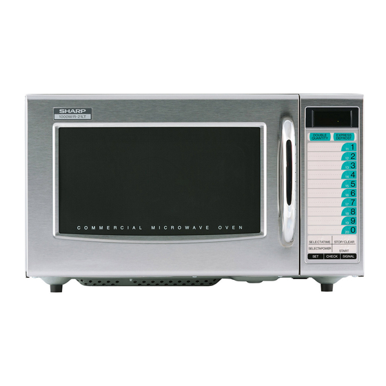
P-10 -------------------- approx. 10% of FULL Power P-0 ---------------------- No power throughout the cooking time DOUBLE QUANTITY pad EXPRESS DEFROST pad Ten number pads SELECTATIME pad STOP/CLEAR pad SELECTAPOWER pad (R-21LTF only) START pad SET pad CHECK pad SIGNAL pad Oven Cavity Light UL Listed. -
Page 8: Chapter 5. General Information 1] Grounding Instructions
6. STOP/CLEAR pad; touch to stop operation of oven and clear 9. Door hinges remaining heating time 10.Door seals and sealing surfaces 7. SELECTAPOWER pad for setting variable power level (R-21LTF only) 11.Door handle 8. START pad; touch to operate oven after door is closed and time is 12.Oven door with see-through window... -
Page 9: Chapter 6. Operation Description Of Operating Se- Quence
[1] DESCRIPTION OF OPERATING SEQUENCE The following is a description of component functions during oven operation. 1. OFF CONDITION 3. POWER LEVEL P-0 TO P-90 COOKING (R-21LTF only) Closing the door activates door sensing switch and secondary inter- lock switch. (In this condition, the monitor switch contacts are opened.) When Variable Cooking Power is programmed, the 120 volts A.C. -
Page 10: Oven Schenatic
R21LTF [2] OVEN SCHENATIC 1. Off Condition SCHEMATIC NOTE: CONDITION OF OVEN 1. DOOR CLOSED 2. “ . “ APPEARSED THERMAL THERMAL CUT-OUT CUT-OUT NOISE FILTER 125ºC (OVEN) 145ºC (MAG.) POWER TRANSFORMER AC120V 60 Hz CAPACITOR 1.00 μF CONTROL UNIT 2300V DOOR SENSING SWITCH... -
Page 11: Description And Function Of Components
R21LTF [3] DESCRIPTION AND FUNCTION OF COMPONENTS 1. DOOR OPEN MECHANISM CAUTION: BEFORE REPLACING A BLOWN MONITOR FUSE TEST THE DOOR SENSING SWITCH, PRIMARY INTERLOCK The door is opened by grasping the door handle, refer to Figure D-1. RELAY (RY2), RELAY (RY3) SECONDARY INTERLOCK When the door handle is grasped, the handle lever is pulled. -
Page 12: Chapter 7. Troubleshooting Guide
R21LTF CHAPTER 7. R21LTF TROUBLESHOOTING GUIDE Service Manual Never touch any part in the circuit with your hand or an uninsulated tool while the power supply is connected. When troubleshooting the microwave oven, it is helpful to follow the Sequence of Operation in performing the checks. Many of the possible causes of trouble will require that a specific test be performed. -
Page 13: Procedure A: Magnetron Assembly Test
R21LTF CHAPTER 8. R21LTF TEST PROCEDURES Service Manual [1] Procedure A: MAGNETRON ASSEMBLY TEST 1. Disconnect the power supply cord, and then remove outer case. 2. Open the door and block it open. 3. Discharge high voltage capacitor. 4. To test for an open filament, isolate the magnetron from the high voltage circuit. A continuity check across the magnetron filament leads should indicate less than 1 ohm. -
Page 14: Procedure D: High Voltage Capacitor Test
R21LTF 6. Reinstall the outer case (cabinet). 7. Reconnect the power supply cord after the outer case is installed. 8. Run the oven and check all functions. NOTE: Be sure to use an ohmmeter that will supply a forward bias voltage of more than 6.3 volts. [4] Procedure D: HIGH VOLTAGE CAPACITOR TEST 1. -
Page 15: Procedure F: Primary Interlock System Test
R21LTF 7. Reconnect the power supply cord after the outer case is installed. 8. Run the oven and check all functions. [7] Procedure F: PRIMARY INTERLOCK SYSTEM TEST 1. DOOR SENSING SWITCH 1. Disconnect the power supply cord, and then remove outer case. 2. -
Page 16: Procedure I: Noise Filter Test
R21LTF 4. If the monitor fuse is blown when the door is opened, check the primary interlock relay, secondary interlock switch and monitor switch according to the "TEST PROCEDURE" for those switches before replacing the blown monitor fuse. CAUTION: BEFORE REPLACING A BLOWN MONITOR FUSE, TEST THE PRIMARY INTERLOCK RELAY, SECONDARY INTERLOCK SWITCH, DOOR SENSING SWITCH AND MONITOR SWITCH FOR PROPER OPERATION. -
Page 17: Procedure K: Key Unit Test
R21LTF If the key unit is defective. 1) Disconnect the power supply cord and then remove outer case. 2) Open the door and block it open. 3) Discharge high voltage capacitor. 4) Replace the key unit. 5) Reconnect all leads removed from components during testing. 6) Re-install the outer case (cabinet). -
Page 18: Procedure L: Relay Test
R21LTF SELECTA DOUBLE START POWER QUANTITY SELECTA EXPRESS STOP/ CHECK TIME DEFROST CLEAR SIGNAL R-21LTF DOUBLE START QUANTITY SELECTA EXPRESS STOP/ CHECK TIME CLEAR DEFROST SIGNAL R-21LVF [13] Procedure L: RELAY TEST 1. Disconnect the power supply cord, and then remove outer case. - Page 19 R21LTF Only pattern at “a” is broken. *Insert jumper wire J1 and solder. Pattern at “a” and “b” are broken. *Replace control unit. 5) Make a visual inspection of the varistor. Check for burned damage and examine the transformer with a tester for the presence of layer short-circuit (check the pri- mary coil resistance which is approximately 915Ω±10%).
-
Page 20: Chapter 9. Touch Control Panel Assem
R21LTF CHAPTER 9. R21LTF TOUCH CONTROL PANEL ASSEMBLY Service Manual [1] OUTLINE OF TOUCH CONTROL PANEL The touch control section consists of the following units as shown in 10)Sound-body Driving Circuit the touch control panel circuit. This is a circuit for driving sound body by IC1 output. (1) Key Unit (2) Control Unit 11)Relay Driving Circuit... -
Page 21: Procedure For Checking/Clearing Service Counts Of Microwave Oven
R21LTF 5) Ensure that these leads remain isolated from other components Disconnect the touch control panel completely from the oven and oven chassis by using insulation tape. proper, and short both ends of the door sensing switch (on PWB) of the touch control panel, which brings about an operational state 6) After that procedure, re-connect the power supply cord. -
Page 22: Other Setting And Checking Pro- Cedure
#3 : Ex. defrost is paused after 50% of cooking time has lapsed when 5 key is entered, otherwise it is paused at the end of each stage. (Total operation time 1234 hours set) #4 : For R-21LTF, change selectapower key to signal key. CHECK 9 – 3... - Page 23 R21LTF DISPLAY PAUSE End of each stage After 10% of total cooking time is passed After 90% of total cooking time is passed START There is no pause 2) To check the constants of Express defrost. " ": Flicker / : 0.1 sec BUZZER DISPLAY INDICATOR...
-
Page 24: Chapter 10. Precautions For Using Lead-Free Solder
R21LTF CHAPTER 10. R21LTF PRECAUTIONS FOR USING LEAD-FREE SOLDER Service Manual [1] Employing lead-free solder The "Main PWB" of this model employs lead-free solder. This is indicated by the "LF" symbol printed on the PWB and in the service manual. The suf- fix letter indicates the alloy type of the solder. -
Page 25: Adjustment Procedure 1] Warning
4. The door is bent or warped. 4. If the outer case (cabinet) is not fitted. WARNING FOR WIRING To prevent an electric shock, take the following precau- 3) Sharp edge: tions. Bottom plate, Oven cavity, Waveguide flange Chassis 1. Before wiring, supportand other metallic plate. -
Page 26: Power Transformer Removal
R21LTF [3] POWER TRANSFORMER REMOVAL 1. Disconnect the power supply cord and remove outer case. 6. Disconnect the main wire harness from the power transformer. 2. Open the oven door and block it open. 7. Remove the two (2) screws and two (2) VCP caps holding the transformer to base plate. -
Page 27: Oven Lamp And Lamp Socket Removal
R21LTF [7] OVEN LAMP AND LAMP SOCKET REMOVAL 1. Disconnect the power supply cord, and remove outer case. 2. Open the door and block it open. Oven lamp socket 3. Discharge high voltage capacitor. 4. Lift up the oven lamp socket from air intake duct. Terminal 5. -
Page 28: Power Supply Cord Replacement
R21LTF 2. INSTALLATION MAKE SURE THAT THE FAN BLADE ROTATES SMOOTH AFTER INSTALLED. 1. Install the fan motor to the fan duct with the two (2) screws. MAKE SURE THAT THE AXIS OF THE SHAFT IS NOT 2. Install the fan blade to the fan motor shaft according to the following SLANTED. -
Page 29: Door Sensing Switch/Secondary Interlock Switch And Monitor Switch Adjustment
R21LTF 5. Disconnect the leads from all switches. 6. Remove the two (2) screws holding the latch hook to the oven cav- ity. Latch Hook 7. Remove the latch hook. 8. Push the retaining tab outward slightly and remove the switch. Tabs Secondary 2. -
Page 30: Antenna Motor Shaft Replacement
R21LTF 3) Now, the door case is free NOTE: At this moment, the door badge is attached on the door case. Choke Cover 2. REINSTALL OF THE DOOR 1. Reinstall all door parts except the choke cover 2. Catch two (2) pins of door panel on two (2) holes of upper and lower oven hinges. - Page 31 R21LTF 4. Remove the antenna motor from the oven cavity bottom plate, 2. Set the direction of the stirrer antenna and antenna holder so that referring to "ANTENNA MOTOR REMOVAL". the hole of the antenna holder fit to the centre of the stirrer antenna's big blade.
-
Page 32: Installation Of Ceramic Shelf
R21LTF [16] INSTALLATION OF CERAMIC SHELF 1. Disconnect the power supply cord. WARNING: Make sure that the rubber packing is not caught between the oven door and the oven cavity front plate, 2. Open the door and block it open. to avoid possible exposure to excessive microwave 3. -
Page 33: Chapter 12. Circuit Diagrams
R21LTF CHAPTER 12. R21LTF CIRCUIT DIAGRAMS Service Manual [1] Pictorial Diagram (Figure S-1) RECTIFIER H.V. NEUTRAL EARTH CN-B CN-A CN-G RY2 RY3 Figure S-1. Pictorial Diagram 12 – 1... -
Page 34: Control Panel Circuit (Figure S-2A And S-2B)
R21LTF [2] Control Panel Circuit (Figure S-2a and S-2b) 1. R21LTF 4.7K 2.7K 4.7K 4.7K 0.1u/50V 47u/10V HZ4A2 0.1u/50V 0.1u/50V 47u/10V 4.7K 4.7K 0.1u/50V 0.1u/50V 2200u/25V 7u/10 VRS1 (J1) Figure S-2. Control Panel Circuit for R-21LTF 12 – 2... - Page 35 R21LTF 2. R-21LVF 4.7K 2.7K 4.7K 0.1u/50V 47u/10V HZ4A2 0.1u/50V 0.1u/50V 47u/10V 4.7K 4.7K 0.1u/50V 0.1u/50V 2200u/25V 47u/10V VRS1 (J1) Figure S-2. Control Panel Circuit for R-21LVF 12 – 3...
-
Page 36: Printed Wiring Board (Figure S-3)
R21LTF [3] Printed Wiring Board (Figure S-3) R 30 R 83 (C 83) R 82 (C 82) R 81 (C 81) R 80 (C 80) R 58 R 57 R 56 R 55 R 54 R 53 R 52 R 51 R 50 (R 91) (R 90) -
Page 37: Parts List
DOOR PROTECTION SHEET (SPADFA435WRE0) (SPADPA204WRE0) BOTTOM PAD ASSEMBLY (FPADBA386WRK0) INSTRUCTION BOOK PACKING CASE Not Replaceable Items. SPAKCE434WREZ [R-21LTF] SPAKCE425WREZ [R-21LVF] This document has been published to be used for after sales service only. The contents are subject to change without notice. - Page 38 R21LTF [1] OVEN PARTS 1-10 4-28 7-13 4-10 7-13 7-13 4-25 7-12 4-32 4-26 1-13 4-34 4-26 4-24 4-27 4-14 4-19 4-15 4-36 4-16 7-10 4-40 7-11 7-12 1-12 4-23 4-18 4-24 4-21 4-20 4-21 4-21 4-22 4-20 4-13 4-33 4-29 1-11 1-15...
- Page 39 R21LTF PRICE PART PARTS CODE DESCRIPTION RANK MARK RANK [1] OVEN PARTS ELECTRIC PARTS FFS-BA033WRKZ Monitor fuse20A and monitor switch (V-5220Q) QSW-MA085WRE0 Door sensing switch QSW-MA135WRE0 Secondary interlock switch FACCDA116WREZ Power supply cord FH-DZA119WRKZ High voltage rectifier assembly RC-QZA235WRE0 High voltage capacitor RC-QZA336WRZZ High voltage capacitor for production use (Interchangeable) RMOTEA376WRE0...
- Page 40 R21LTF PRICE PART PARTS CODE DESCRIPTION RANK MARK RANK [1] OVEN PARTS TCAUAA245WRR0 Cover caution SCREWS, NUTS AND WASHERS XHPS740P08K00 Screw : 4mm x 8mm XEPS740P25000 Screw : 4mm x 25mm LX-CZA038WRE0 Special screw LX-CZ0052WRE0 Special screw LX-EZA042WRE0 Special screw XBPWW40P04000 Screw : 4mm x 4mm XHPS740P08000...
- Page 41 R21LTF [2] DOOR AND CONTROL PANEL PARTS 3-2-3 3-2-2 5-1-15 3-2-1 5-1-16 5-1-14 5-1-2 5-1-12 5-1-16 5-1-18 5-1-4-2 5-1-16 5-1-4-5 5-1-13 5-1-4-4 5-1-4 5-1-1 5-1-4-3 5-1-4-1 5-1-4-5 5-1-16 5-1-12 5-1-8 5-1-7 5-1-17 5-1-9 5-1-11 5-1-3 5-1-8 5-1-17 5-1-5 5-1-6 5-1-10 Actual wire harness may be different from illustration.
- Page 42 [2] DOOR AND CONTROL PANEL PARTS CONTROL PANEL PARTS DPWB-A417DRKZ Control unit [R-21LTF] DPWB-A418DRKZ Control unit [R-21LVF] FPNLCB912WRKZ Control panel frame with key unit [R-21LTF] FPNLCB913WRKZ Control panel frame with key unit [R-21LVF] 3-2-1 FUNTKB173WREZ Key unit [R-21LTF] 3-2-1 FUNTKB174WREZ...
- Page 43 R21LTF INDEX PRICE PART PRICE PART PARTS CODE PARTS CODE RANK MARK RANK RANK MARK RANK PFILWA060WRP0 1-4-29 [ C ] PGLSPA516WRE0 2-5-1-4-3 CDORFB052WRKZ 2-5-1 PHOK-A160WRFZ 1-4-8 [ D ] PPACGA171WRE0 2-5-4 DPWB-A417DRKZ 2-3-1 PSHEPA644WRE0 1-4-30 DPWB-A418DRKZ 2-3-1 PSHEPA649WRE0 2-5-1-2 [ F ] PSHEPA673WRE0 1-4-40...
- Page 44 COPYRIGHT © 2006 BY SHARP CORPORATION ALL RIGHTS RESERVED. © COPYRIGHT XXXX BYSHARP CORPORATION No part of this publication may be reproduced, stored in retrieval systems, or transmitted in anyform or by ALL RIGHTS RESERVED. any means, electronic, mechanical, photocopying, re- cording, or other wise, without prior written permission of the publisher.