Sharp R-21LCF Service Manual
Light duty commercial microwave oven
Hide thumbs
Also See for R-21LCF:
- Operation manual (24 pages) ,
- Specification sheet (2 pages) ,
- Operation manual (24 pages)
Table of Contents
Advertisement
1000W / R-21L C
PRECAUTIONS TO BE OBSERVED BEFORE AND
DURING SERVICING TO AVOID POSSIBLE EXPO-
SURE TO EXCESSIVE MICROWAVE ENERGY
BEFORE SERVICING
CHAPTER 1. WARNING TO SERVICE PERSONNEL
CHAPTER 2. MICROWAVE MEASUREMENT PRO-
CEDURE
CHAPTER 3. FOREWORD AND WARNING
CHAPTER 4. PRODUCT DESCRIPTION
CHAPTER 5. GENERAL INFORMATION
CHAPTER 6. OPERATION
SHARP CORPORATION
SERVICE MANUAL
TIME GUIDE FOR ONE
SERVIN G
15 - 30 sec.
30 - 60 sec.
Bagel, Roll
Hot Dog
Muffin, Pastry
Pizza Slice
Pie Slice
Small Sandwic h
1 - 2 min.
2 - 3 min.
Beverag e, Soup
Cassero le, Stew
Large Sandwic h
Chili, Chowde r
Popcorn , 1.5 oz.
Popcorn , 3.5 oz.
1
40 50
1.5
30
E
F
G
D
H
20
C
I
B
2
10
J
A
0
K
In the interest of user-safety the oven should be restored to its original
L
2.5
M
N
3
O
T
S
P
6
R
Q
4
condition and only parts identical to those specified should be used.
5
INST RUC TION
S
With the door
close d,turn the
WARNING TO SERVICE PERSONNEL: Microwave ovens contain
the desir ed
timer to
time. Oven
will begin
opera ting imme
diate ly.
To shut oven
off manu ally,re
to "0".
turn timer
circuitry capable of producing very high voltage and current, con-
tact with following parts may result in a severe, possibly fatal,
electrical shock. (High Voltage Capacitor, High Voltage Power
Transformer, Magnetron, High Voltage Rectifier Assembly, High
Voltage Harness etc..)
CONTENTS
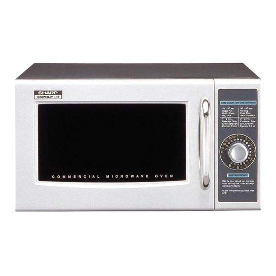
LIGHT DUTY COMMERCIAL
MICROWAVE OVEN
R-21LCF
MODEL
CHAPTER 7. TROUBLESHOOTING GUIDE
CHAPTER 8. TEST PROCEDURES
CHAPTER 9. TOUCH CONTROL PANEL ASSEMBLY
CHAPTER 10. PRECAUTIONS FOR USING LEAD-
FREE SOLDER
CHAPTER 11. COMPONENT REPLACEMENT AND
ADJUSTMENT PROCEDURE
CHAPTER 12. CIRCUIT DIAGRAMS
Parts List
This document has been published to be used
for after sales service only.
The contents are subject to change without notice.
R21LCF
S7607R21LCFP/
Advertisement
Table of Contents

Related Manuals for Sharp R-21LCF


Summary of Contents for Sharp R-21LCF
-
Page 1: Microwave Oven
R21LCF SERVICE MANUAL S7607R21LCFP/ LIGHT DUTY COMMERCIAL MICROWAVE OVEN 1000W / R-21L C R-21LCF TIME GUIDE FOR ONE MODEL SERVIN G 15 - 30 sec. 30 - 60 sec. Bagel, Roll Hot Dog Muffin, Pastry Pizza Slice Pie Slice Small Sandwic h 1 - 2 min. -
Page 2: Table Of Contents
CONTENTS PRECAUTIONS TO BE OBSERVED BEFORE AND [12] Procedure L: RELAY TEST......8-5 DURING SERVICING TO AVOID POSSIBLE EXPO- [13] Procedure M: FOIL PATTERN ON THE SURE TO EXCESSIVE MICROWAVE ENERGY PRINTED WIRING BOARD TEST....8-5 CHAPTER 1. -
Page 3: Precautions To Be Observed Before And During Servicing To Avoid Possible Expo
Before servicing an operative unit, perform a microwave emission check as per the Microwave Measurement Procedure outlined in this service manual. If microwave emissions level is in excess of the specified limit, contact SHARP ELECTRONICS CORPORATION immediately @1-800-237-4277. If the unit operates with the door open, service person should 1) tell the user not to operate the oven and 2) contact SHARP ELECTRONICS CORPORATION and Food and Drug Administration's Center for Devices and Radiological Health immediately. -
Page 4: When The Testing Is Completed
R21LCF CHAPTER 1. R21LCF WARNING TO SERVICE PERSONNEL Service Manual Microwave ovens contain circuitry capable of producing very high voltage and current, contact with following parts may result in a severe, possibly fatal, electrical shock. (Example) High Voltage Capacitor, High Voltage Power Transformer, Magnetron, High Voltage Rectifier Assembly, High Voltage Harness etc.. Read the Service Manual carefully and follow all instructions. -
Page 5: Cedure 1] Requirements:
R21LCF CHAPTER 2. R21LCF MICROWAVE MEASUREMENT PROCEDURE Service Manual [1] Requirements: 1. Microwave leakage limit (Power density limit): The power density of microwave radiation emitted by a microwave oven should not exceed 1mW/ at any point 5cm or more from the external surface of the oven, measured prior to acquisition by a purchaser, and thereafter (through the use- ful life of the oven), 5 mW/cm at any point 5cm or more from the external surface of the oven. -
Page 6: Chapter 3. Foreword And Warning
Service Manual [1] FOREWORD This Manual has been prepared to provide Sharp Electronics Corp. Service Personnel with Operation and Service Information for the SHARP MICROWAVE OVEN, R-21LCF. It is recommended that service personnel carefully study the entire text of this manual so that they will be qualified to render satisfactory customer service. -
Page 7: Chapter 4. Product Description
R21LCF CHAPTER 4. R21LCF PRODUCT DESCRIPTION Service Manual [1] SPECIFICATIONS ITEM DESCRIPTION 120 Volts 14 Amperes Power Requirements 60 Hertz Single phase, 3 wire grounded 1000 watts (IEC Test procedure) Power Output Operating frequency 2450 MHz Width 20-1/2" (520mm) Outer case Dimensions Height 12-1/8"... -
Page 8: Chapter 5. General Information 1] Grounding Instructions
R21LCF CHAPTER 5. R21LCF GENERAL INFORMATION Service Manual [1] GROUNDING INSTRUCTIONS This oven is equipped with a three prong grounding plug. It must be plugged into a wall receptacle that is properly installed and grounded in accor- dance with the National Electrical Code and local codes and ordinances. In the event of an electrical short circuit, grounding reduces the risk of electric shock by providing an escape wire for the electric current. -
Page 9: Chapter 6. Operation Description Of Operating Se- Quence
R21LCF CHAPTER 6. R21LCF OPERATION Service Manual [1] DESCRIPTION OF OPERATING SEQUENCE The following is a description of component functions during oven operation. 1. OFF CONDITION 5) Upon completion of the cooking time, the power transformer, oven lamp, etc. are turned off, and the generation of microwave energy Closing the door activates door sensing switch and secondary inter- is stopped. -
Page 10: Description And Function Of Components
R21LCF 2. Cooking Condition SCHEMATIC NOTE: CONDITION OF OVEN 1. DOOR CLOSED. 2. LIGHT UP DIAL ON. THERMAL THERMAL CUT-OUT CUT-OUT NOISE FILTER 125ºC (OVEN) 145ºC (MAG.) POWER TRANSFORMER AC120V 60 Hz CAPACITOR 1.00 μF CONTROL UNIT 2300V DOOR SENSING SWITCH OVEN ANTENNA... - Page 11 R21LCF 3) If the door is opened, and the primary interlock relay (RY1) and secondary interlock switch contacts fail to open, the monitor fuse blows simultaneously with closing of the monitor switch contacts. CAUTION: BEFORE REPLACING A BLOWN MONITOR FUSE TEST THE DOOR SENSING SWITCH, PRIMARY INTERLOCK RELAY (RY1), SECONDARY INTERLOCK SWITCH AND MONITOR SWITCH FOR PROPER OPERATION.
-
Page 12: Chapter 7. Troubleshooting Guide
R21LCF CHAPTER 7. R21LCF TROUBLESHOOTING GUIDE Service Manual Never touch any part in the circuit with your hand or an uninsulated tool while the power supply is connected. When troubleshooting the microwave oven, it is helpful to follow the Sequence of Operation in performing the checks. Many of the possible causes of trouble will require that a specific test be performed. -
Page 13: Procedure A: Magnetron Assembly Test
R21LCF CHAPTER 8. R21LCF TEST PROCEDURES Service Manual [1] Procedure A: MAGNETRON ASSEMBLY TEST 1. Disconnect the power supply cord, and then remove outer case. 2. Open the door and block it open. 3. Discharge high voltage capacitor. 4. To test for an open filament, isolate the magnetron from the high voltage circuit. A continuity check across the magnetron filament leads should indicate less than 1 ohm. -
Page 14: Procedure D: High Voltage Capacitor Test
R21LCF 6. Reinstall the outer case (cabinet). 7. Reconnect the power supply cord after the outer case is installed. 8. Run the oven and check all functions. NOTE: Be sure to use an ohmmeter that will supply a forward bias voltage of more than 6.3 volts. [4] Procedure D: HIGH VOLTAGE CAPACITOR TEST 1. -
Page 15: Procedure F: Primary Interlock System Test
R21LCF 7. Reconnect the power supply cord after the outer case is installed. 8. Run the oven and check all functions. [7] Procedure F: PRIMARY INTERLOCK SYSTEM TEST 1. DOOR SENSING SWITCH 1. Disconnect the power supply cord, and then remove outer case. 2. -
Page 16: Procedure I: Noise Filter Test
R21LCF 3. Discharge high voltage capacitor. 4. If the monitor fuse is blown when the door is opened, check the primary interlock relay, secondary interlock switch and monitor switch according to the "TEST PROCEDURE" for those switches before replacing the blown monitor fuse. CAUTION: BEFORE REPLACING A BLOWN MONITOR FUSE, TEST THE PRIMARY INTERLOCK RELAY, SECONDARY INTERLOCK SWITCH, DOOR SENSING SWITCH AND MONITOR SWITCH FOR PROPER OPERATION. -
Page 17: Procedure L: Relay Test
R21LCF When testing is completed, 1) Disconnect the power supply cord and then remove outer case. 2) Open the door and block it open. 3) Discharge high voltage capacitor. 4) Reconnect all leads removed from components during testing. 5) Re-install the outer case (cabinet). 6) Reconnect the power supply cord after the outer case is installed. - Page 18 R21LCF 2. Follow the troubleshooting guide given below, if indicator does not light up after above check and repairs are finished. 1) Disconnect the power supply cord and then remove outer case. 2) Open the door and block it open. 3) Discharge high voltage capacitor.
-
Page 19: Chapter 9. Touch Control Panel Assem
R21LCF CHAPTER 9. R21LCF TOUCH CONTROL PANEL ASSEMBLY Service Manual [1] OUTLINE OF TOUCH CONTROL PANEL 1. Control Unit 4) Reset Circuit A circuit to generate a signals which resets the LSI to the initial Control unit consists of LSI, power source circuit, synchronizing signal state when power is supplied. - Page 20 R21LCF Connect an external power source to the power input terminal of 4. Other Precautions the touch control panel, then it is possible to check and repair the 1) Before turning on the power source of the control unit, remove the controls of the touch control panel;...
-
Page 21: Chapter 10. Precautions For Using Lead-Free Solder
R21LCF CHAPTER 10. R21LCF PRECAUTIONS FOR USING LEAD-FREE SOLDER Service Manual [1] Employing lead-free solder The "Main PWB" of this model employs lead-free solder. This is indicated by the "LF" symbol printed on the PWB and in the service manual. The suf- fix letter indicates the alloy type of the solder. -
Page 22: Adjustment Procedure 1] Warning
4. If the outer case (cabinet) is not fitted. 4. The door is bent or warped. WARNING FOR WIRING To prevent an electric shock, take the following precau- 3) Sharp edge: tions. Bottom plate, Oven cavity, Waveguide flange Chassis 1. Before wiring, supportand other metallic plate. -
Page 23: High Voltage Rectifier Assembly And High Voltage Capacitor Removal
R21LCF 6. Disconnect the main wire harness from the power transformer. 8. Remove the transformer. 7. Remove the two (2) screws and two (2) VCP caps holding the 9. Now the power transformer is free. transformer to base plate. [4] HIGH VOLTAGE RECTIFIER ASSEMBLY AND HIGH VOLTAGE CAPACITOR REMOVAL To remove the components, proceed as follows. -
Page 24: Positive Lock Connector (No-Case Type) Removal
R21LCF Figure C-1. Oven lamp socket [8] POSITIVE LOCK CONNECTOR (NO-CASE TYPE) REMOVAL 1. Disconnect the power supply cord, and remove outer case. 2. Open the door and block it open. Terminal 3. Discharge high voltage capacitor. ® 4. Push the lever of positive lock connector. -
Page 25: Power Supply Cord Replacement
R21LCF Coil Shaft Groove joint pliers Shaft These are the positions Axis that should be pinched Stator with pliers. Stator Table Center of bracket Rotor Bracket Rotor Side View Rear View [11] POWER SUPPLY CORD REPLACEMENT 1. REMOVAL Oven Cavity Power Supply Cord 1. -
Page 26: Door Sensing Switch/Secondary Interlock Switch And Monitor Switch Adjustment
R21LCF 2. REINSTALL 2. Re-connect wire leads to each switch. Refer to pictorial diagram. 3. Secure latch hook (with two (2) mounting screws) to oven flange. 1. Re-install each switch in its place. The door sensing switch and monitor switch are in the lower position and the secondary interlock 4. -
Page 27: Antenna Motor Shaft Replacement
R21LCF DOOR HANDLE REMOVAL 1) Make sure that door sensing switch, secondary inter- lock switch and monitor switch are operating properly. 13.Release the latch spring from the tab of the latch angle assembly. (Refer to chapter “Test Procedures”.). 14.Remove the two (2) screws holding the door handle and the latch 2) An approved microwave survey meter should be used angle assembly through the door frame. -
Page 28: Installation Of Ceramic Shelf
R21LCF 5. Install the antenna holder to the oven cavity bottom plate with the one (1) screw and the one (1) washer. Refer to Figure C-8. Screw Antenna holder Washer 6. Install the antenna motor to the oven cavity bottom plate with one (1) screw. - Page 29 R21LCF 6. Push down the rear edge of the ceramic shelf into the oven cavity bottom plate. 7. Now, the ceramic shelf is installed. WARNING: Make sure that the rubber packing is not caught between the oven door and the oven cavity front plate, to avoid possible exposure to excessive microwave energy.
-
Page 30: Chapter 12. Circuit Diagrams
R21LCF CHAPTER 12. R21LCF CIRCUIT DIAGRAMS Service Manual [1] Pictorial Diagram (Figure S-1) CTIFIE H.V. IMAR Figure S-1. Pictorial Diagram 12 – 1... -
Page 31: Control Panel Circuit (Figure S-2)
R21LCF [2] Control Panel Circuit (Figure S-2) HZ11A3 4.7K 0.1u/50V HZ6C3 4.7K 4.7K HZ4C1 0.1u/50V 4.7K INT1 AIN0 0.1u/50V AIN1 AIN2 20 AIN3 21 P00 22 P01 23 P02 24 1.5K 3.3K 4.7K 4.7K 6.2K 4.7K 220u/16V 4.7K 1000u/35V 0.1u/50V 100K 100K 10G471K... -
Page 32: Printed Wiring Board (Figure S-3)
R21LCF [3] Printed Wiring Board (Figure S-3) L D6 L D5 L D7 L D4 L D8 L D3 L D9 L D2 L D10 J P 33 L D1 L D11 L D12 L D13 J P 29 J P 28 J P 27 L D14 J P 26... -
Page 33: Parts List
PARTS LIST LIGHT DUTY COMMERCIAL MICROWAVE OVEN HOW TO ORDER REPLACEMENT PARTS To have your order filled promptly and correctly, please furnish the following information. R-21LCF MODEL 1. MODEL NUMBER 2. REF. NO. 3. PART NO. 4. DESCRIPTION Parts marked "*" may cause undue microwave exposure. - Page 34 R21LCF [1] OVEN PARTS 1-10 4-28 7-13 4-10 7-13 7-13 4-25 7-14 4-32 4-26 1-13 4-34 4-26 4-24 4-27 4-14 4-19 4-15 4-36 4-16 7-10 4-40 7-11 7-12 1-12 4-23 4-18 4-24 4-21 4-20 4-21 4-21 4-22 4-20 4-13 4-33 4-29 1-11 1-15...
- Page 35 R21LCF PRICE PART PARTS CODE DESCRIPTION RANK MARK RANK [1] OVEN PARTS ELECTRIC PARTS Monitor fuse20A and monitor switch (V-5220Q) FFS-BA033WRKZ Door sensing switch QSW-MA085WRE0 Secondary interlock switch QSW-MA135WRE0 Power supply cord FACCDA116WREZ High voltage rectifier assembly FH-DZA119WRKZ High voltage capacitor RC-QZA235WRE0 High voltage capacitor for production use (Interchangeable) RC-QZA336WRZZ...
- Page 36 R21LCF PARTS CODE PRICE PART DESCRIPTION RANK MARK RANK [1] OVEN PARTS Screw : 4mm x 8mm XHPS740P08000 Screw : 4mm x 8mm XHTS740P08000 Screw : 3mm x 6mm XHPS730P06000 7-10 Screw : 4mm x 8mm XHTS740P08RV0 7-11 Screw : 4mm x 12mm XOTS740P12000 7-12 XOTS740P08000...
- Page 37 R21LCF [2] DOOR AND CONTROL PANEL PARTS 3-2-1 3-2-2 5-1-15 5-1-16 5-1-14 5-1-2 5-1-12 5-1-16 5-1-18 5-1-4-2 5-1-16 5-1-13 5-1-4-5 5-1-4-4 5-1-4 5-1-1 5-1-4-3 5-1-4-1 5-1-4-5 5-1-16 5-1-12 5-1-8 5-1-7 5-1-17 5-1-9 5-1-11 5-1-3 5-1-8 5-1-17 5-1-5 5-1-6 5-1-10 Actual wire harness may be different from illustration.
- Page 38 R21LCF PRICE PART PARTS CODE DESCRIPTION RANK MARK RANK [2] DOOR AND CONTROL PANEL PARTS CONTROL PANEL PARTS Control unit DPWB-A416DRKZ Panel sub assembly FPNLCB911WRKZ 3-2-1 Timer sheet HPNLTA200WREZ 3-2-2 C/P case GCOVAA260WRP0 User caution label TCAUAA076WRR0 Timer knob JKNBKA606WRM0 Screw;...
- Page 39 R21LCF INDEX PRICE PART PRICE PART PARTS CODE PARTS CODE RANK MARK RANK RANK MARK RANK PRNGFA001WRF0 2-3-6 [ C ] PSHEPA644WRE0 1-4-30 CDORFB052WRKZ 2-5-1 PSHEPA649WRE0 2-5-1-2 [ D ] PSHEPA673WRE0 1-4-40 DPWB-A416DRKZ 2-3-1 PSHEPA674WRE0 1-4-38 [ F ] PSHEPA686WRE0 2-5-1-12 FACCDA116WREZ 1-1-4...
- Page 40 COPYRIGHT © 2006 BY SHARP CORPORATION ALL RIGHTS RESERVED. © COPYRIGHT XXXX BYSHARP CORPORATION No part of this publication may be reproduced, stored in retrieval systems, or transmitted in anyform or by ALL RIGHTS RESERVED. any means, electronic, mechanical, photocopying, re- cording, or other wise, without prior written permission of the publisher.