Table of Contents
Advertisement
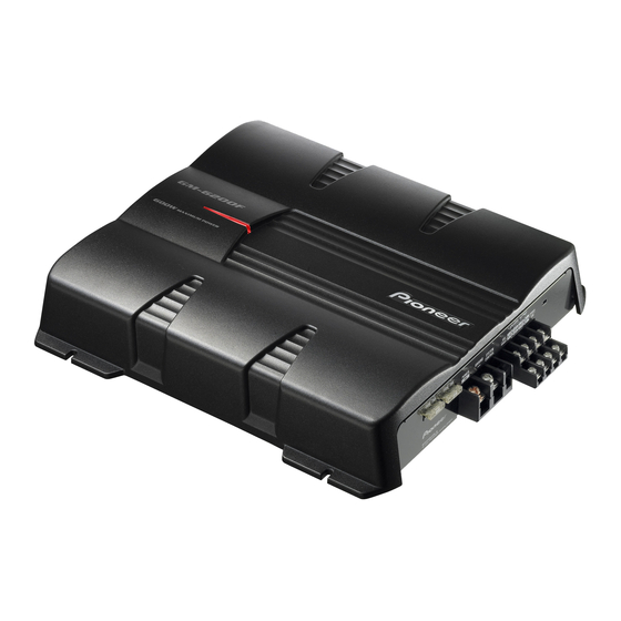
BRIDGEABLE FOUR-CHANNEL POWER AMPLIFIER
GM-6200F
GM-6200F
GM-6200F
GM-6200F
For details, refer to "Important Check Points for Good Servicing".
PIONEER CORPORATION
PIONEER ELECTRONICS (USA) INC. P.O. Box 1760, Long Beach, CA 90801-1760, U.S.A.
PIONEER EUROPE NV Haven 1087, Keetberglaan 1, 9120 Melsele, Belgium
PIONEER ELECTRONICS ASIACENTRE PTE. LTD. 253 Alexandra Road, #04-01, Singapore 159936
PIONEER CORPORATION 2005
/XU/EW
/XU/ES
/XU/CN
4-1, Meguro 1-chome, Meguro-ku, Tokyo 153-8654, Japan
GM-6200F/XU/UC
ORDER NO.
CRT3520
/XU/UC
K-ZZA. OCT. 2005 Printed in Japan
Advertisement
Table of Contents

Summary of Contents for Pioneer GM-6200F/XU/UC
- Page 1 PIONEER CORPORATION 4-1, Meguro 1-chome, Meguro-ku, Tokyo 153-8654, Japan PIONEER ELECTRONICS (USA) INC. P.O. Box 1760, Long Beach, CA 90801-1760, U.S.A. PIONEER EUROPE NV Haven 1087, Keetberglaan 1, 9120 Melsele, Belgium PIONEER ELECTRONICS ASIACENTRE PTE. LTD. 253 Alexandra Road, #04-01, Singapore 159936 PIONEER CORPORATION 2005 K-ZZA.
-
Page 2: Safety Information
Health & Safety Code Section 25249.6 - Proposition 65 - Service Precaution You should conform to the regulations governing the product (safety, radio and noise, and other regulations), and should keep the safety during servicing by following the safety instructions described in this manual. GM-6200F/XU/UC... - Page 3 To protect products from damages or failures during transit, the shipping mode should be set or the shipping screws should be installed before shipment. Please be sure to follow this method especially if it is specified in this manual. GM-6200F/XU/UC...
-
Page 4: Table Of Contents
4. PCB CONNECTION DIAGRAM ........................18 4.1 AMP UNIT ..............................18 5. ELECTRICAL PARTS LIST ..........................22 6. ADJUSTMENT ............................... 27 7. GENERAL INFORMATION ..........................28 7.1 DIAGNOSIS ............................. 28 7.1.1 DISASSEMBLY ............................. 28 7.1.2 CONNECTOR FUNCTION DESCRIPTION ..................29 8. OPERATIONS ..............................30 GM-6200F/XU/UC... -
Page 5: Specifications
1. SPECIFICATIONS GM-6200F/XU/UC... - Page 6 GM-6200F/XU/UC...
- Page 7 GM-6200F/XU/UC...
-
Page 8: Exploded Views And Parts List
• Screw adjacent to mark on the product are used for disassembly. " • For the applying amount of lubricants or glue, follow the instructions in this manual. (In the case of no amount instructions,apply as you think it appropriate.) 2.1 PACKING GM-6200F/XU/UC... - Page 9 PACKING SECTION PARTS LIST Mark Description GM-6200F/XU/UC GM-6200F/XU/EW GM-6200F/XU/ES GM-6200F/XU/CN Screw Assy CEA5330 CEA5330 CEA5330 CEA5330 Screw BYC40P180FTB BYC40P180FTB BYC40P180FTB BYC40P180FTB Polyethylene Sheet CNM4338 CNM4338 CNM4338 CNM4338 Cord Assy CDE7737 CDE7737 CDE7737 CDE7737 Protector CHP3066 CHP3066 CHP3066 CHP3066 Polyethylene Bag...
-
Page 10: Exterior
2.2 EXTERIOR GM-6200F/XU/UC... - Page 11 > Fuse (FU101, FU102) (25A) CEK1329 Terminal CND2458 Choke Coil (L902, L903) CTH1326 Holder CND2466 (2) CONTRAST TABLE GM-6200F/XU/UC, GM-6200F/XU/EW, GM-6200F/XU/ES and GM-6200F/XU/CN are constructed the same except for the following: Mark Description GM-6200F/XU/UC GM-6200F/XU/EW GM-6200F/XU/ES GM-6200F/XU/CN Heat Sink CNR1833...
-
Page 12: Block Diagram And Schematic Diagram
Note: When ordering service parts, be sure to refer to " EXPLODED VIEWS AND PARTS LIST" or "ELECTRICAL PARTS LIST". Large size SCH diagram +18.5dBs(MAX) +18.3dBs Guide page +18.3dBs Detailed page A FREQ A FREQ B FREQ B FREQ 320µH 320µH GM-6200F/XU/UC... - Page 13 The > mark found on some component parts indicates the importance of the safety factor of the part. Therefore, when replacing, be sure to use parts of identical designation. -12.2dBs +27.8dBs A GAIN B GAIN 8R2K 8R2K 50µH > > GM-6200F/XU/UC...
- Page 14 GM-6200F/XU/UC...
- Page 15 GM-6200F/XU/UC...
- Page 16 10K(A) 10K(A) GM-6200F/XU/UC...
- Page 17 10K(A) GM-6200F/XU/UC...
-
Page 18: Pcb Connection Diagram
1.The parts mounted on this PCB include all necessary parts for several destination. For further information for respective destinations, be sure to check with the schematic dia- gram. 2.Viewpoint of PCB diagrams Capacitor Connector SIDE A SIDE B P.C.Board Chip Part FU101 FU102 GM-6200F/XU/UC... - Page 19 SIDE A B GAIN B FREQ RCA OUTPUT INPUT SELECT A FREQ A GAIN GM-6200F/XU/UC...
- Page 20 AMP UNIT D604 GM-6200F/XU/UC...
- Page 21 SIDE B GM-6200F/XU/UC...
-
Page 22: Electrical Parts List
Q 316 (B,214,135) Transistor 2SC2713 Q 659 (B,153,189) Transistor 2SA1576A Q 701 (B,141,84) Transistor DTA114EU Q 317 (B,249,78) Transistor 2SC2713 Q 702 (B,135,83) Transistor DTC114TU Q 318 (B,209,95) Transistor 2SC2713 Q 703 (B,148,84) Transistor 2SC4081 Q 319 (B,243,148) Transistor 2SC2713 GM-6200F/XU/UC... - Page 23 RS1/16S103J (A,307,23) 10k Ω (A)(A GAIN) CCS1265 VR601 R 303 (B,259,140) RS1/16S103J (A,307,203) 10k Ω (A)(B GAIN) CCS1265 VR602 R 304 (B,224,129) RS1/16S103J > FU101 (A,18,63) Fuse 25A CEK1329 R 305 (B,257,82) RS1/16S333J > FU102 (A,18,40) Fuse 25A CEK1329 GM-6200F/XU/UC...
- Page 24 RD1/4PU100J R 668 (A,141,180) RD1/4PU221J R 370 (A,219,41) RD1/4PU100J R 669 (B,156,185) RS1/16S222J R 371 (A,218,189) RD1/4PU100J R 670 (B,156,189) RS1/16S563J R 372 (A,198,189) RD1/4PU100J R 701 (B,145,84) RS1/16S222J (A,224,42) 0.1 Ω R 377 CCN1155 R 831 (A,302,165) RD1/4PU683J GM-6200F/XU/UC...
- Page 25 C 338 (B,181,37) CCSRCH220J50 R 939 (A,102,49) RD1/2PM100J C 339 (B,257,193) CCSRCH220J50 R 940 (A,115,104) RD1/2PM220J C 340 (B,179,193) CCSRCH220J50 C 341 (B,233,37) CCSRCH220J50 R 941 (A,134,104) RD1/2PM220J C 342 (B,212,37) CCSRCH220J50 R 942 (A,117,87) RD1/2PM220J R 943 (A,109,189) RD1/2PM560J GM-6200F/XU/UC...
- Page 26 C 865 (B,275,132) CCSRCH470J50 C 866 (B,302,186) CCSRCH470J50 C 875 (B,296,40) CKSRYB471K50 C 876 (B,283,101) CKSRYB471K50 C 877 (B,282,139) CKSRYB471K50 C 878 (B,300,197) CKSRYB471K50 C 901 (A,133,65) CEAT100M50 C 902 (A,141,63) CEAT221M16 C 903 (A,151,69) CQHA102J2A C 904 (A,140,58) CFTNA105J50 GM-6200F/XU/UC...
-
Page 27: Adjustment
6. ADJUSTMENT There is no information to be shown in this chapter. GM-6200F/XU/UC... -
Page 28: General Information
7. GENERAL INFORMATION 7.1 DIAGNOSIS 7.1.1 DISASSEMBLY Removing the Case (Fig.1) Remove the six screws and then remove the Case. Case Fig.1 Removing the Amp Unit (Fig.2) Remove the fourteen screws and then remove the Amp Unit. Amp Unit Fig.2 GM-6200F/XU/UC... -
Page 29: Connector Function Description
7.1.2 CONNECTOR FUNCTION DESCRIPTION GM-6200F/XU/UC... -
Page 30: Operations
8. OPERATIONS GM-6200F/XU/UC... - Page 31 GM-6200F/XU/UC...
- Page 32 GM-6200F/XU/UC...
- Page 33 GM-6200F/XU/UC...


