LG LWD3010ST Service Manual
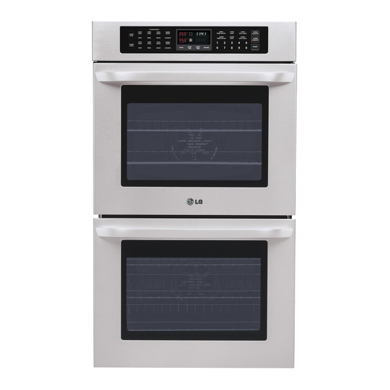
30” electric convection built-in oven
Hide thumbs
Also See for LWD3010ST:
- Owner's manual (76 pages) ,
- Manual de usuario (40 pages) ,
- Specifications (2 pages)
Table of Contents

Related Manuals for LG LWD3010ST


Summary of Contents for LG LWD3010ST
- Page 1 Internal Use Only Website http://biz.lgservice.com 30” ELECTRIC CONVECTION BUILT-IN OVEN SERVICE MANUAL MODEL: LWD3010ST CAUTION BEFORE SERVICING THE UNIT, READ THE SAFETY PRECAUTIONS IN THIS MANUAL. June, 2010 P/NO : MFL37118314 Printed in Korea...
-
Page 2: Safety Precautions
SAFETY PRECAUTIONS • Repairs of the appliance should be carried out by a licensed technician only. Incorrect repairs may result in dangerous situations. If you need repairs, contact an LG Service Center or your dealer. • If the power cord is defective, it must be replaced by a qualified service agent with a UL listed range cord. -
Page 3: Table Of Contents
TABLE OF CONTENTS GENERAL- - - - - - - - - - - - - - - - - - - - - - - - - - - - - - - - - - - - - - - - - - - - - - - - - - - - - - - - - - - - - - - - - - - - - - - - - - - - - - - - - - - - - - - - - - - - 1-1 ~ 1-6 •... - Page 4 - Removing the Convection motor assembly - - - - - - - - - - - - - - - - - - - - - - - - - - - - - - - - - - - - - - - - - - - - - - - - - - - - - - - - - - - - - - - - - - - - - - - - - 3-8 - Removing the Hidden bake element - - - - - - - - - - - - - - - - - - - - - - - - - - - - - - - - - - - - - - - - - - - - - - - - - - - - - - - - - - - - - - - - - - - - - - - - - - - 3-8 ~ 3-9 DISASSEMBLY INSTRUCTIONS(LOWER) - - - - - - - - - - - - - - - - - - - - - - - - - - - - - - - - - - - - - - - - - - 3-10 ~ 3-11 - Removing the Thermal limiter (Double Line Brake_Lower) - - - - - - - - - - - - - - - - - - - - - - - - - - - - - - - - - - - - - - - - - - - - - - - - - - - 3-11...
-
Page 5: General
GENERAL READ ALL INSTRUCTIONS BEFORE USE READ ALL INSTRUCTIONS BEFORE USE Read and follow all instructions before using your oven to prevent the risk of fire, electric shock, injury to person, or damage when using the range. This guide don’t cover all possible conditions that may occur. For further assistance contact your service agent or manufacturer. - Page 6 GENERAL READ ALL INSTRUCTIONS BEFORE USE READ ALL INSTRUCTIONS BEFORE USE SAFETY PRECAUTIONS • Be certain all packing materials are removed • Be certain your appliance is properly installed from the appliance before operating. and grounded by a qualified technician. Keep plastics, clothes, and paper away from •...
- Page 7 GENERAL READ ALL INSTRUCTIONS BEFORE USE READ ALL INSTRUCTIONS BEFORE USE • Before replacing your oven light bulb, CHILD SAFETY switch off the electrical power to the oven at the main fuse or circuit breaker panel. WARNING Failure to do so can result in severe personal injury, death, or electrical shock.
- Page 8 GENERAL READ ALL INSTRUCTIONS BEFORE USE READ ALL INSTRUCTIONS BEFORE USE SAFETY WHEN CLEANING • Important Instruction. In the event the self • Do Not Clean Door Gasket. The door gasket is clean error code F is displayed, and error essential for a good seal.
- Page 9 GENERAL MODEL & SERIAL NUMBER LABEL AND MODEL & SERIAL NUMBER LABEL AND TECH SHEET LOCA TION TECH SHEET LOCA TION The Model/Serial Number label and Tech Sheet locations are shown below. Model & Serial Number Location Tech Sheet Location...
-
Page 10: Specifications
SPECIFICA TIONS SPECIFICA TIONS Product Specification List Items Specifications Remarks Model name LWD3010ST Built-in Double wall oven North American market Rating power source 240 V~ 60 Hz Single phase & 4-wires Heat source Sheath heater & Carbon heater Max power 7.8 KW... -
Page 11: Using Your Oven
USING YOUR OVEN GENERAL INFORMA TION GENERAL INFORMA TION Rating Label Cooking Guide Refer to the owners manual for recommendations Model numbers are recorded on the rating label. of times and temperatures. Times, rack position, Rating label is located on the lower left bottom and temperatures may vary depending on area of the controller. -
Page 12: Control Panel Feature
USING YOUR OVEN CONTROL P ANEL FEA TURES CONTROL P ANEL FEA TURES READ THE INSTRUCTIONS CAREFULLY BEFORE USING THE OVEN. For satisfactory use of your oven, become familiar with the various features and functions of the oven as described below. UPPER OVEN 18. -
Page 13: Setting The Clock
USING YOUR OVEN 1. SETTING THE CLOCK 6. SPECIAL FUNCTION: 6 TYPES OF CATEGORY Desired CLOCK START 1) CONVECTION AUTO CONVERSION Time 1. Touch the SETTING pad once. 2. Touch “1” pad for ENABLE 2. START, CLEAR/OFF or “2” pad for DISABLE 3. -
Page 14: Bake
USING YOUR OVEN 7. BAKE 14. TIMED COOK, DELAYED TIMED COOK Desired BAKE Desired Temperature START BAKE START Temperature 8. BROIL COOK Desired time START TIME Desired Broil Broil Full / Center START Desired START Desired Temp TIME start time START High / Med / Low 9 ROAST... -
Page 15: Disassembly Instructions
DISASSEMBLY INSTRUCTIONS This section instructs you on how to service each component inside the range. The components and their locations are shown below. COMPONENT LOCA TIONS COMPONENT LOCA TIONS Main PCB SMPS PCB Display PCB Upper Oven Light Upper Door Latch Assembly Oven Sensor Upper Door Switch... -
Page 16: Disassembly Instructions(Upper)
DISASSEMBLY INSTRUCTIONS(UPPER) REPLACING THE CONTROL P ANEL AND RELA TED COMPONENTS REPLACING THE CONTROL P ANEL AND RELA TED COMPONENTS 6. Disconnect the connectors from PCB assembly WARNING and separate control panel carefully. • ELECTRIC SHOCK HAZARD - Unit must be disconnected from electrical outlet when making repairs, replacements, adjustments. - Page 17 DISASSEMBLY INSTRUCTIONS(UPPER) 2) To remove the Relay PCB, Remove 1 screw If there is a failure of this motor the following steps and slide relay PCB out. can be followed to unlock the door manually. Disconnect the connectors from PCB assembly Unlocking status Locking status and separate Relay PCB assembly.
-
Page 18: Disassembly Instructions(Upper/Lower)
DISASSEMBLY INSTRUCTIONS(UPPER/LOWER) REPLACING OVEN CA VITY COMPONENTS REPLACING OVEN CA VITY COMPONENTS 1) To remove the broil element: WARNING a. Remove the 4 screws from the front and rear brackets. • ELECTRIC SHOCK HAZARD - Unit must be disconnected from electrical outlet when making repairs, replacements, adjustments. - Page 19 DISASSEMBLY INSTRUCTIONS(UPPER/LOWER) b. Remove the 4 convection element screws. 4) To remove the halogen lamp & socket assembly (The convection element is fragile. Care a. There are three halogen lamp & socket should be taken to avoid any risk of injury) assembly in the oven cavity.
-
Page 20: Replacing Other Electrical Components
DISASSEMBLY INSTRUCTIONS(UPPER) REPLACING OTHER ELECTRICAL COMPONENTS REPLACING OTHER ELECTRICAL COMPONENTS Vent motor Thermal limiter WARNING • ELECTRIC SHOCK HAZARD - Unit must be disconnected from electrical outlet when making repairs, replacements, adjustments. Replace all panels before operating oven. Failure to do so can result in death or electrical shock. - Page 21 DISASSEMBLY INSTRUCTIONS(UPPER) 4) Squeeze tabs on switch and slide through the COOLING FAN (BLOWER) front. • Self Clean Mode: The cooling fans can Disconnect the wires from terminals. operate at 2 different speeds based on temperature. If the temp is above 482°F/250°C the fans will operate on high.
- Page 22 DISASSEMBLY INSTRUCTIONS(UPPER) 1) To Remove Thermal Limiter (Double Line Brake 3) To remove the hidden bake element Upper), remove the screw and 2 wire leads. a. Remove the Vent cover, Barrier bracket. THERMAL LIMITER • To shut down the heaters The thermostats are located at the back of the oven next to each broil element and wired in series with each Double Line Break relay.
- Page 23 DISASSEMBLY INSTRUCTIONS(UPPER) d. Bend the insulator up and remove the 1 screw. e. Carefully pull the hidden bake element and its BAKE HEATER_COVER out of the oven.\ f. When replacing the Bake Element cover use the 5 screws provided.
-
Page 24: Disassembly Instructions(Lower)
DISASSEMBLY INSTRUCTIONS(LOWER) 7. To remove the Thermal limiter, Convection motor, 1) To Remove Thermal Limiter (Double Line Brake Lower), remove the screw and 2 wire leads. and Bake Element from the lower oven Follow the steps as follows. Remove Lower rear cover. THERMAL LIMITER •... - Page 25 DISASSEMBLY INSTRUCTIONS(LOWER) 4) To remove the hidden bake element Remove screws from middle support. a. Remove the barrier bracket. Barrier Middle support bracket Lower Door lock motor b. To remove the convection motor assembly. assembly (refer to the following page 3-8) Lower door switch Lower vent motor 8.
-
Page 26: Disassembly Instructions(Upper/Lower)
DISASSEMBLY INSTRUCTIONS(UPPER/LOWER) REMOVING & REINST ALLING THE LIFT -OFF OVEN DOOR REMOVING & REINST ALLING THE LIFT -OFF OVEN DOOR To replace the door: CAUTION 1. Firmly grasp The door is very heavy. Be careful both sides of the door at the top. when removing and lifting the door. -
Page 27: Removing The Oven Door Handle & Glass
DISASSEMBLY INSTRUCTIONS(UPPER/LOWER) REMOVING THE OVEN DOOR HANDLE & GLASS REMOVING THE OVEN DOOR HANDLE & GLASS 6. To remove the door handle & trim. CAUTION a. Remove 2 screws for handle and replace. • Be careful when you work on the b. - Page 28 DISASSEMBLY INSTRUCTIONS(UPPER/LOWER) 5) Lift the COVER_INNER-2 off the door liner. 6) Lift the hinge out of the door liner slot. To remove the oven door glass assembly: 7) Lift the COVER_INNER-1 off the door liner. COVER_INNER-1 COVER_INNER-1 COVER_INNER-1 COVER_INNER-1 COVER_INNER-1 COVER_INNER-1 COVER_INNER-1 COVER_INNER-1...
-
Page 29: Removing The Oven Door Gasket
DISASSEMBLY INSTRUCTIONS(UPPER/LOWER) REMOVING THE OVEN DOOR GASKET REMOVING THE OVEN DOOR GASKET 1. Remove oven door 3. Pull the ends of the gasket out of the liner holes. 2. Pull the oven door gasket clips out of the liner Liner Hole holes until all of the clips are removed. -
Page 30: Component Test
COMPONENT TEST Before testing any components, perform the following checks: NOTE: 1. The most common cause for control failure is corrosion on connectors. Therefore, disconnecting and reconnecting wires will be necessary throughout test procedures 2. If this is a new product check all connections before replacing parts. 1. -
Page 31: Door Locking Motor
Components Test procedures Results Normal: Approximately 2550 Ω Door locking Motor 1. Refer to page 3-10 for disassembly Replace if: Infinite (opened) 2. Measure the resistance below 5 Ω (shorted) (Multiple meter scale: R x 1000) Door latch Door latch Door locking micro 1. -
Page 32: Oven Thermistor
Components Test procedures Results Normal: Approximately Oven Thermistor 1. Refer to page 3-5 for disassembly 1090 Ω 2. Measure the resistance after cool down Replace if: Infinite (opened) (Multiple meter scale: R x 1000) below 10 Ω (shorted) NOTE: Ω Value should be tested at room temperature (77F/25˚C) NOTE: After checking for the continuity of switch, make sure to reconnect leads... -
Page 33: Broil Element
Components Test procedures Results Normal: Approximately Broil Element 1. Refer to page 3-4 for disassembly Inner: 22.5 Ω 2. Measure the resistance after cool down Outer: 36.9 Ω (Multiple meter scale : R x 1) Replace if: Infinite (opened) NOTE: Outer Broil element use Outer yellow and Blue terminals to check resistance. -
Page 34: Composition Of Control
COMPOSITION OF CONTROL Main PCB Main PCB P/N : EBR64624503 CN03 CN03 CN03 CN03 CN03 CN03 CN03 CN03 CN03 CN03 CN03 CN03 CN03 CN03 CN03 CN03 CN03 CN03 CN03 CN03 CN03 CN03 CN07 CN07 CN07 CN07 CN07 CN07 CN07 CN07 CN07 CN07 CN07... - Page 35 COMPOSITION OF CONTROL Relay PCB Relay PCB P/N : EBR64624603 CN02 CN02 CN02 CN02 CN02 CN02 CN02 CN02 CN02 CN02 CN02 CN02 CN02 CN02 CN02 CN02 CN02 CN02 CN02 CN02 CN02 CN02 CN01 CN01 CN01 CN01 CN01 CN01 CN01 CN01 CN01 CN01 CN01...
- Page 36 COMPOSITION OF CONTROL Display Display P/N : EAJ61309901 Key PCB Key PCB P/N : EBR67339001...
-
Page 37: Diagnosis Through Schematic
DIAGNOSIS THROUGH SCHEMATIC Symptom : Dead -. Check : Open/Short Symptom : Oven lamp not operating -. Check : Open/Short Symptom : No heating (F-9, F-19) -. Check : Open/short Symptom : Oven hot (F-6, F-16) -. Check : All heater Relays Short SYSTEM PCB Symptom : Dead... -
Page 38: Check The Failure Code (F-Code)
CHECK THE FAILURE CODE (F-code) ■ When the oven has some failure on cooking - Oven may stop operating and F-code will display in display window. - Some F-codes display immediately(F-3,F-9, F-19), but other codes will store in EEPROM memory and not displayed ■... - Page 39 SAFETY CAUTION & ERROR CODE SUMMARY 1.1 Safety Caution • Normal State is power OFF, unless described differently as power ON. 1.2 Error Code Summary Code Description Operation Opened Sensor Upper Oven Thermistor remain open for over 1 min, after cook (Upper) starts Shorted Sensor...
-
Page 40: Checking Flow Chart By Fairure
CHECKING FLOW CHART BY FAIRURE Symptom Check Point 1. Power Failure 1. Check Electric Wiring (Dead) 2. Check the thermostat 2. No Display 3. Check the SMPS PCB... -
Page 41: No Display (No Power)
CHECKING FLOW CHART BY FAIRURE No Display (No Power) Control Dead Check AC input of SMPS PCB - SMPS PCB CN1 (pin 1 and 3) Select a function Any beeping Sound? Replace the MAIN PCB (EBR64624503) 120V AC? Normal? Replace the DISPLAY Replace the SMPS PCB (EAJ61309901) (EBR64624701) - Page 42 CHECKING FLOW CHART BY FAIRURE No Display (No Power) Check thermostat Normal? Check the connection of L1 and N Replace thermostat from power inlet. Normal? Fix or replace the lead wire...
- Page 43 CHECKING FLOW CHART BY FAIRURE No Display (No Power) Check the connection 1. between SYSTEM and SMPS PCB, 2. between SYSTEM and MAIN PCB, 3. between DISPLAY and MAIN PCB, Normal? Replace the SYSTEM PCB (EBR43296803) Normal? Replace the MAIN PCB (EBR64624503)
-
Page 44: No Heating (Including F9, F19 Error)
CHECKING FLOW CHART BY FAIRURE Symptom Check Point 1. No heating 1. Check Electric Wiring 2. F-9 2. Check the thermostat. 3. F-19 3. The Heater’s Resistance. 4. Check the Sensor (thermistor). - Page 45 CHECKING FLOW CHART BY FAIRURE Oven does not heat (including F-9, F-19 Error) No heating UPPER Disconnect power Check the electric wiring 1. Harness of Relay connection. 2. Each heater’s connection. 3. system and Relay PCB connection (CN11, CN12) LOWER Fix or replace the lead wire Normal? Check the thermostat open/short...
- Page 46 CHECKING FLOW CHART BY FAIRURE Oven does not heat (including F-9, F-19 Error) Measure the Resistor of each heater Between the DLB Relay's L2 and each heater Relay's Harness point of Figure 1 (measure the resistance after cooling down) UPPER Normal: Resistor Bake...
- Page 47 CHECKING FLOW CHART BY FAIRURE Oven does not heat (including F-9, F-19 Error) Normal? Replace the error heater Connect the power Check the value of thermistor by using the test mode • To enter the testmode, follow these steps: 1. press the “clear” key 2.
- Page 48 CHECKING FLOW CHART BY FAIRURE Oven does not heat (including F-9, F-19 Error) Normal? Disconnect the oven sensor and check the value (measure the resistance after cooling down) Normal:approximately 1.06kΩ at 65°F ~ 1.12 kΩ at 85°F. Normal? Replace the oven sensor Replace the SYSTEM PCB Replace the Relay PCB (EBR43296803)
-
Page 49: Door Lock System Failure (Including F10, F20 Error)
CHECKING FLOW CHART BY FAIRURE Symptom Check Point 1. Door Lock System 1. Check the Electric wiring Failure 2. Check the Motor’s Resistance 2. F-10, F-20 9-10... - Page 50 CHECKING FLOW CHART BY FAIRURE Door lock system error F-10, F-20 Error Just after self-clean start,the door lock motor starts to rotate. During that time if the door lock switch does not operate properly after rotating twice, then supervising circuit detects a Door Lock failure and the F-10, F-20 error code appears.
- Page 51 CHECKING FLOW CHART BY FAIRURE Door lock system error F-10, F-20 Error Check the door locking motor (measure the resistance) normal: approximately 2.6 kΩ abnormal: infinite or below 5 Ω Normal? Replace the door Check the looseness of CN08 locking motor Normal? Reconnect 9-12...
- Page 52 CHECKING FLOW CHART BY FAIRURE Door lock system error F-10, F-20 Error Check the Relay PCB’s electric connection (CN01, CN03) Check the connection between system PCB and relay PCB(CN11, CN12) Normal? Reconnect Replace the Relay PCB (EBR64624603) Normal? Replace the SYSTEM PCB (EBR43296803) 9-13...
- Page 53 CHECKING FLOW CHART BY FAIRURE Symptom Check Point 1. Sensing Fail 1. Check the electric wiring 2. F-1 2. Check the test Mode 3. F-2 3. Check the sensor(thermistor) resistance 4. F-4 (approximately 1.06 kΩ at 65°F ~ 1.12 kΩ at 85°F.) 5.
- Page 54 CHECKING FLOW CHART BY FAIRURE Oven sensing error F-1, F-2, F-4, F-5 error Main oven sensing failed Connect the power Check the value of thermistor by using the test mode • To enter the testmode, follow these steps: 1. press the “clear” key 2.
- Page 55 CHECKING FLOW CHART BY FAIRURE Oven sensing error F-1, F-2, F-4, F-5 error Normal? Disconnect the oven sensor and check the value (measure the resistance after cooling down) Normal:approximately 1.06kΩ at 65°F ~ 1.12 kΩ at 85°F. Normal? Replace the oven sensor Replace the SYSTEM PCB Replace the Relay PCB (EBR43296803)
-
Page 56: Oven Hot (Including F6, F16 Error)
CHECKING FLOW CHART BY FAIRURE Symptom Check Point 1. Oven hot 1. Check the Resistance of the Relay. 2. F-6 3. F-16 9-17... - Page 57 CHECKING FLOW CHART BY FAIRURE Oven hot error F-6, F-16 error Oven is hot (F-6, F-16) Disconnect the power and oven sensor. Check the oven sensor value (measure the resistance after cooling down) Normal:approximately 1.06 kΩ at 65°F ~ 1.12 kΩ at 85°F Normal? Replace the oven sensor Remove the relay PCB harness...
- Page 58 CHECKING FLOW CHART BY FAIRURE Oven hot error F-6, F-16 error Normal? Replace the Relay PCB (EBR64624603) Replace the SYSTEM PCB (EBR43296803) 9-19...
-
Page 59: No Key Input Or F3
CHECKING FLOW CHART BY FAIRURE No key input Or F-3 Key does not input Check the connection KEY PCB’S CN01 and between MAIN PCB’S CN603 Normal? Reconnect Replace Replace the control supporter Normal? Normal? Replace the Main PCB (EBR64624503) 9-20... -
Page 60: F11 Error (Communication Error)
CHECKING FLOW CHART BY FAIRURE F-11 error (communication error) F-11 error Check the connection between MAIN PCB’S CN06 and SYSTEM PCB’S CN13 Normal? Reconnect Replace the SYSTEM PCB (EBR43296803) Reset failure log and Check the F-code. 1. press the “clear” key 2. -
Page 61: Schematic Diagram
SCHEMATIC DIAGRAM AC INPUT Thermostat (LOWER) Relay P.C.B. CN01 CN03 BLOWER BLOWER HI BLOWER BLOWER BLOWER CONV. FAN CONV. CONV. DOOR CONV. FAN MOTOR DOOR DOOR MOTOR MOTOR BLOWER HI DOOR PRI. SEC. MOTOR RY10 OVEN LAMP OVEN OVEN TRANSFORMER OVEN OVEN LAMP... -
Page 62: Strip Circuits
STRIP CIRCUITS STRIP CIRCUITS Complete the following steps before checking electric oven circuit : 1.Check the line voltage, household fuse or circuit breaker. 2.Check for loose wiring or mis-wiring within electric range. NOTE: The following individual circuits are for use in diagnosis, and are shown in the ON position. NOTE: “(Up)”... - Page 63 Crisp Convection mode Conv. Bake & Conv. Roast mode Note: In case of Bake mode, the convection fan will operate only for preheating. 10-3...
- Page 64 Bake & Roast mode Self Clean mode 10-4...
- Page 65 Warm & Proof mode 10-5...
-
Page 66: Exploded View
#EV# EXPLODED VIEW INTRODUCTION MODEL: CONTROLLER PARTS CAVITY PARTS DOOR PARTS MFL1 MAX1 MAY1 MFL3 MBM2 -11-1-... - Page 67 #EV# UPPER DOOR PARTS W257 1703 1000 W225 W149 1040 1121 1120 W256 W149 1401 W149 1033 W256 1023 W225 1023 1009 1008 W256 1402 W149 1703 1704 W149 -11-2-...
- Page 68 #EV# LOWER DOOR PARTS W257 1703 1000 W225 W149 1040 1121 1120 W256 W149 1401 W149 1030 W256 1023 W225 1023 1009 1402 1008 W256 W149 1703 1704 W149 11-3...
- Page 69 #EV# CONTROLLER PARTS W108 2119 W105 2006 2050 3006 2381 2055 W108 W105 2030 2118 W258 -11-4-...
- Page 70 #EV# UPPER CAVITY PARTS 5014 W144 5504 W235 5041 W144 5001 W146 W237 5070 W105 W236 W144 W241 W105 5010 W144 5508 W144 5503 5071 5611 3006 3006 5517 W144 W144 5414 5612 W144 W144 5124 W144 5718 W144 W144 5073 W144 3062...
- Page 71 #EV# LOWER CAVITY PARTS W144 5702 W144 5124 5414 W144 5517 5073 5449 W144 5073 W144 5507 W144 W144 W144 3006 3062 5703 W144 W144 3006 5562 W144 5440 W104 5561 5550 5119 5713 5540 5602 5450 W144 5550 W231 3006 5513 W144...
- Page 72 #EV# ASSEMBLY W144 W144 3029 W144 3605 3604 W144 W144 3601 W144 3603 3013 W144 5723 3602 W144 3311 W144 W144 W144 5097 W144 W144 W144 W144 5535 W144 W144 5545 3013 5527 W144 W144 W121 3018 3044 3144 W144 3312 -11-7-...