HP BladeSystem c3000 Technology Brief
Hide thumbs
Also See for BladeSystem c3000:
- Setup and installation manual (94 pages) ,
- Manual (38 pages) ,
- Quickspecs (35 pages)
Table of Contents
Advertisement
Quick Links
HP BladeSystem c3000 Enclosure technologies
technology brief
Abstract.............................................................................................................................................. 2
Overview of HP BladeSystem c3000 Enclosure ....................................................................................... 2
HP Thermal Logic technologies .............................................................................................................. 4
Active Cool fans .............................................................................................................................. 5
HP PARSEC architecture.................................................................................................................... 6
Thermal Logic for the server blade and enclosure ................................................................................. 7
Power supplies and enclosure power subsystem................................................................................... 8
HP BladeSystem Power Sizer ......................................................................................................... 9
Pooled power ............................................................................................................................ 10
Dynamic Power Saver mode ........................................................................................................ 11
Power Regulator ......................................................................................................................... 11
Power Capping for each server blade........................................................................................... 11
Interconnect options and infrastructure.................................................................................................. 12
Fabric connectivity and port mapping............................................................................................... 13
Virtual Connect .............................................................................................................................. 16
Enclosure-based DVD ROM................................................................................................................. 17
Onboard Administrator ...................................................................................................................... 17
Insight Display ............................................................................................................................... 19
Web GUI...................................................................................................................................... 20
Command-line interface .................................................................................................................. 20
Onboard Administrator cabling ....................................................................................................... 20
Enclosure link cabling ..................................................................................................................... 20
Recommendations.............................................................................................................................. 21
Summary .......................................................................................................................................... 21
Appendix A. Acronyms in text............................................................................................................. 22
Appendix B. Fan, power supply, and device bay population guidelines ................................................... 23
For more information.......................................................................................................................... 28
Call to action .................................................................................................................................... 28
Advertisement
Table of Contents

Related Manuals for HP BladeSystem c3000


Summary of Contents for HP BladeSystem c3000
-
Page 1: Table Of Contents
HP BladeSystem c3000 Enclosure technologies technology brief Abstract.............................. 2 Overview of HP BladeSystem c3000 Enclosure ..................2 HP Thermal Logic technologies ......................4 Active Cool fans ..........................5 HP PARSEC architecture........................6 Thermal Logic for the server blade and enclosure ................. 7 Power supplies and enclosure power subsystem................... -
Page 2: Abstract
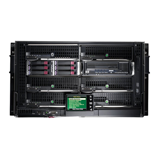
Abstract The HP BladeSystem c3000 Enclosure is the next generation in an evolution of the entire rack- mounted infrastructure. The c3000 Enclosure is designed for remote sites, small and medium-sized businesses, and data centers with special power and cooling constraints. This technology brief... - Page 3 Tested up to 10 Gbit on Midplane Tested up to 10 Gbit on midplane OA Serial/USB connections In front In rear Figures 1 and 2 show the front and rear view of the HP BladeSystem c3000 Enclosure. Figure 1. HP BladeSystem c3000 Enclosure – front view...
-
Page 4: Hp Thermal Logic Technologies
Figure 2. HP BladeSystem c3000 Enclosure – rear view HP Thermal Logic technologies HP BladeSystem c-Class products have been designed with a variety of HP Thermal Logic technologies―a set of technologies integrated across server blades, enclosures, and interc onnect modules―all of which combined provide significant power and cooling benefits in comparison to traditional rack and tower based servers. -
Page 5: Active Cool Fans
Active Cool fans Quite often, dense, full-featured, small form-factor servers use very small fans designed to provide localized cooling in the specific areas needed by the server blade. Because such fans generate fairly low airflow (in cubic feet per minute, or CFM) at medium backpressure, a single server often requires multiple fans to ensure adequate cooling. -
Page 6: Hp Parsec Architecture
Figure 4. HP BladeSystem c3000 self-sealing enclosure Base BladeSystem c3000 Enclosures ship with four installed fans that support up to four half-height devices in device bays 1, 2, 5, and 6, or two full-height server blades in device bays 1 and 2. -
Page 7: Thermal Logic For The Server Blade And Enclosure
Figure 5. The c3000 Enclosure fan bay and device bay population guidelines Thermal Logic for the server blade and enclosure The server blade design uses precise ducting throughout the server blade to manage airflow and temperature based on the unique thermal requirements of all the critical components. The airflow is tightly ducted to ensure that no air bypasses the server blade and to obtain the most thermal work from the least amount of air. -
Page 8: Power Supplies And Enclosure Power Subsystem
AC power supplies auto-switch between 100VAC and 240VAC, to provide deployment options. The BladeSystem c3000 Enclosure houses the power supplies in the same enclosure as the server blades, storage blades, and interconnect modules (Figure 7). The power supply modules connect to a passive power backplane that distributes power to all the components in a shared manner. -
Page 9: Hp Bladesystem Power Sizer
Figure 7. HP BladeSystem c3000 Enclosure supports up to six power supplies The new, high efficiency HP c3000 power supplies provide greater than 90 percent efficiency in AC to DC conversion. These power supplies use the ProLiant universal form factor so they can also be used in other ProLiant servers. -
Page 10: Pooled Power
UPS. In the event of a single power supply failure, the redundant power supply will take over the load of the failed power supply. Figure 8. Redundant HP BladeSystem c3000 power supplies connected to an HP R5500 UPS Connecting to PDUs with AC redundancy to each rack If N+N AC redundancy is configured, then total power available is the amount from the A or B side containing fewer power supplies (3+3 configuration = up to 3600W). -
Page 11: Dynamic Power Saver Mode
Connecting with no power redundancy configured If no power redundancy is configured, the total power available is defined as the power available from all power supplies installed (six power supplies installed = up to 7200W). Any power supply or AC line failure may cause the system to power off. The Onboard Administrator manages power allocation rules of various components and can limit overall power capacity for the enclosure. -
Page 12: Interconnect Options And Infrastructure
This combination provides a 1x (500Mb/s) transfer rate with 2x = 2 lanes (1Gb/s). Figure 9. Diagram of the HP BladeSystem c3000 signal midplane By taking advantage of the similar four-wire differential transmit and receive mechanism, the signal midplane can support either network-semantic protocols (for example, Ethernet, Fibre Channel, and InfiniBand) or memory-semantic protocols (PCIe), using the same signal traces. -
Page 13: Fabric Connectivity And Port Mapping
The rear of the enclosure includes four interconnect bays that can accommodate four single or two redundant interconnect modules. All interconnect modules plug directly into these interconnect bays. Each HP BladeSystem c3000 Enclosure requires two interconnect switches or two pass-thru modules, side-by-side, for a fully redundant configuration. - Page 14 Figure 11. HP BladeSystem c3000 interconnect bay numbering For interconnect bay mapping purposes, it does not matter in which device bay a server blade is installed. The mezzanine connectors always connect to the same interconnect bays. Because the connections between the device bays and the interconnect bays are hard-wired through the signal midplane, the server mezzanine cards must be matched to the appropriate type of interconnect module.
- Page 15 • NIC 3 — Interconnect bay 1 port 1 • NIC 4 — Interconnect bay 1 port 9 Figure 12. Port mapping for HP BladeSystem c3000 full-height server blades to interconnect bays Half-height server blades connect to a single power and signal connector on the signal midplane.
-
Page 16: Virtual Connect
Figure 13 lists the available configurations for half-height devices installed in device bay N (1–8). Figure 13. Port mapping for HP BladeSystem c3000 half-height server blades to interconnect bays Port mapping differs slightly between full-height and half-height server blades due to the support for additional mezzanine cards on the full-height version. -
Page 17: Enclosure-Based Dvd Rom
Enclosure-based DVD ROM The HP BladeSystem c3000 Enclosure has an optional CD/DVD ROM drive that installs in the front of the enclosure. The Insight Display and Onboard Administrator allow system administrators to connect and disconnect the media device to one or multiple servers at a time. In addition, a browser-based console is available through the iLO functionality of each server blade. - Page 18 The Onboard Administrator aggregates up to eight iLO 2 ports in a c3000 Enclosure, simplifying cable management and providing a graphical interface to launch individual server iLO management interfaces. The rear of each module has an LED (blue unit identification) that can be enabled locally or remotely and can be used to identify the enclosure from the back of the rack.
-
Page 19: Insight Display
• Cooling—The Onboard Administrator makes sure there is sufficient cooling capacity for the server blade or interconnect module by retrieving thermal information from all of the server blades, power supplies, Active Cool fans, and interconnect modules in the enclosure. • Location—The Onboard Administrator checks the locations of server blades, Active Cool fans, and power supplies to determine if they are placed to receive proper cooling and to support the chosen power configuration. -
Page 20: Web Gui
USB connectivity. A separate rear-loading Onboard Administrator link module contains RJ-45 ports for enclosure link-up/link-down connectivity and Onboard Administrator network access (Figure 15). Figure 15. HP BladeSystem c3000 Onboard Administrator module Enclosure link cabling The Onboard Administrator link module contains two enclosure link ports to allow any active Onboard Administrator module to access linked enclosures. -
Page 21: Recommendations
Enclosure. Summary The HP BladeSystem c3000 Enclosure is the next generation of a new modular computing architecture that consolidates and simplifies infrastructure, reduces operational cost, and delivers IT services more effectively. The c3000 Enclosure is designed for remote sites, small and medium-sized businesses, and data centers with special power and cooling constraints. -
Page 22: Appendix A. Acronyms In Text
Appendix A. Acronyms in text The following acronyms are used in the text of this document. Table A-1. Acronyms Acronym Acronym expansion Alternating current British thermal unit Cubic feet per minute Command line interface Direct current Double data rate Fibre Channel InfiniBand Integrated Lights Out iSCSI... -
Page 23: Appendix B. Fan, Power Supply, And Device Bay Population Guidelines
Appendix B. Fan, power supply, and device bay population guidelines Figure B-1. HP BladeSystem c3000 Enclosure – Fan population guidelines. For correct operation, fans and server blades must be installed in the correct fan bays. The Onboard Administrator will ensure that fans and server/storage blades are correctly placed before allowing systems to power on. - Page 24 Figure B-2. HP BladeSystem c3000 Enclosure – Power supply population guidelines Table B-1. Power supply placement Number of power supplies Power supply bays used 1 and 4 1, 2, 4, and 5 All power supply bays filled Table B-2. Power supply redundancy options...
- Page 25 Figure B-3. HP BladeSystem c3000 Enclosure – Full-height server blade device bay numbering. Full--height servers should be populated from bottom to top when viewing from the front of the enclosure. With four fans, only the bottom two device bays can be used; with six fans, all device bays can be used.
- Page 26 Figure B-5. The c3000 Enclosure is divided by sheet metal panels into 2 full-height zones. Each horizontal zone is divided vertically by a removable shelf to make a maximum of 8 half-height device bays. These zones reflect the PCIe bus mapping in the signal midplane and limit placement of the server blade/storage blade combination. The signal midplane has a direct PCIe link connecting adjacent paired device bays.
- Page 27 When installing a companion blade (HP StorageWorks SB40c Storage Blade, HP PCI Expansion Blade, or HP StorageWorks Ultrium 448c Tape Blade), the companion blade can be installed in either of the paired device bays (1/2, 3/4, 5/6, or 7/8) with a half-height server blade installed in the other paired device bay.
-
Page 28: For More Information
Send comments about this paper to TechCom@HP.com. © 2007 Hewlett-Packard Development Company, L.P. The information contained herein is subject to change without notice. The only warranties for HP products and services are set forth in the express warranty statements accompanying such products and services.