Advertisement
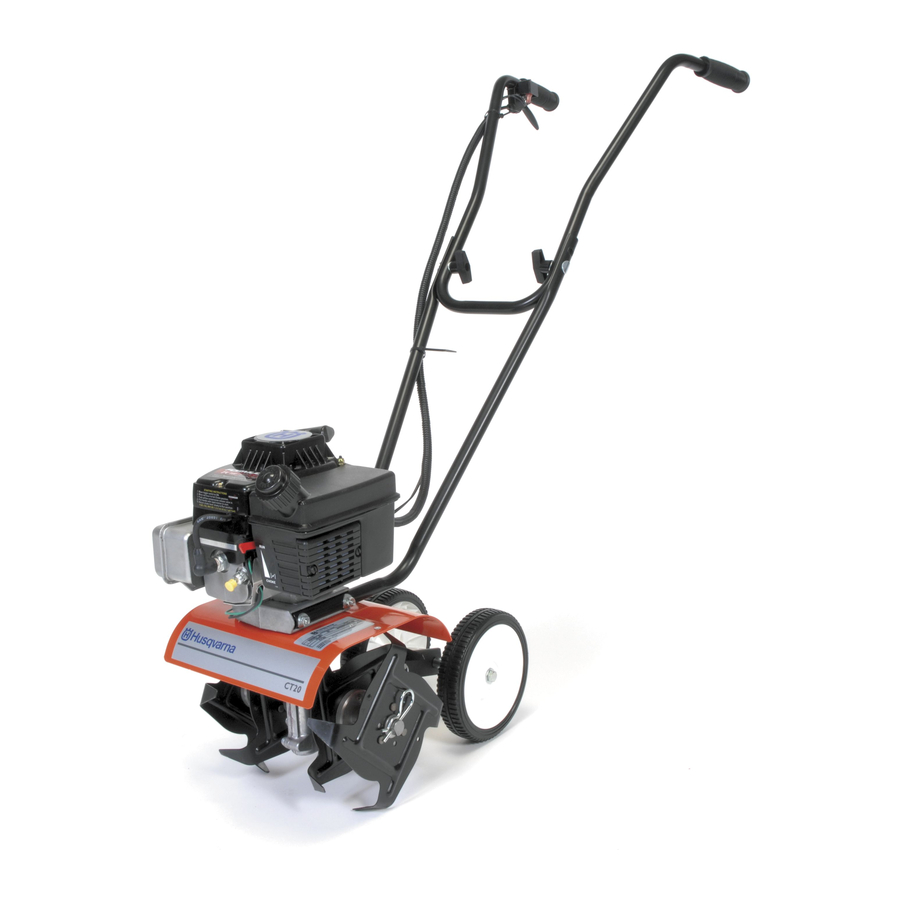
Instruction Book - Model CT20
Read and keep this book for future reference.
This book contains important information on
SAFETY, ASSEMBLY, OPERATION, and MAINTENANCE.
PRODUCT INFORMATION
The owner must be certain
that all the product information
is included with the unit.
This information includes the
INSTRUCTION BOOKS, the
REPLACEMENT PARTS and the
WARRANTIES.
This information must be included
to make sure state laws and other laws
are followed.
MS-3615MA
Advertisement
Table of Contents

Related Manuals for Husqvarna CT20


Summary of Contents for Husqvarna CT20
- Page 1 Instruction Book - Model CT20 Read and keep this book for future reference. This book contains important information on SAFETY, ASSEMBLY, OPERATION, and MAINTENANCE. PRODUCT INFORMATION The owner must be certain that all the product information is included with the unit.
-
Page 2: Warranty
SECTION 2: HUSQVARNA’S OBLIGATIONS UNDER THE WARRANTY Husqvarna will repair or replace defective components without charge for parts or labor if a component fails because of a defect in material or workmanship during the warranty period. - Page 3 It is the Owner’s and Retailer’s responsibility to make certain that the Warranty Registration Card is properly filled out and mailed to Husqvarna Forest & Garden Company. This card should be mailed within ten (10) days from the date of purchase in order to confirm the warranty and to facilitate post-sale service.
-
Page 4: Table Of Contents
WARRANTY SAFETY RULES INTERNATIONAL SYMBOLS ASSEMBLY OPERATION MAINTENANCE TROUBLE SHOOTING CHART REPAIR PARTS Record the following information about your unit so that you will be able to provide it in case of loss or theft. MODEL NUMBER: PURCHASE DATE: DEALER’S NAME AND ADDRESS: CITY: IMPORTANT: This unit is equipped with an internal combustion engine and must not be used on or near any unimproved forest−covered, brush−covered or grass−covered land... - Page 5 OWNER’S INFORMATION This instruction book is written for a person with some mechanical ability. Like most service books, not all the steps are described. Steps on how to loosen or tighten fasteners are steps anyone can follow with some mechanical ability. Read and follow these instructions before you use the unit. Know your product: If you understand the unit and how the unit operates, you will get the best performance.
-
Page 6: Safety Rules
Safe Operation Practices for Cultivator WARNING: Look for this symbol to point out important safety precautions. It means: “Attention! Become Alert! Your Safety Is Involved.” WARNING: To prevent acciden- tal starting when setting−up, transporting, adjusting or mak- ing repairs, always disconnect spark plug wire and put wire where it cannot contact the spark plug . - Page 7 S Be careful when tilling in hard ground. The tines may catch in the ground and propel the tiller forward. If this occurs, let go of the handlebars and do not restrain the ma- chine. S Use extreme care when reversing or pull- ing the machine towards you.
-
Page 8: International Symbols
INTERNATIONAL SYMBOLS IMPORTANT: Many of the following symbols are located on your unit or on literature sup- plied with the product. Before you operate the unit, learn and understand the purpose for each symbol. Control And Operating Symbols Slow Safety Warning Symbols WARNING Thrown Objects. -
Page 9: Assembly
ASSEMBLY PARTS PACKED SEPARATELY IN CARTON 1 − Owner’s Manual (not shown) 1 − Upper Handle 1 − Right Lower Handle 1 − Left Lower Handle 1 − Parts Bag WARNING: Always wear safety glasses or eye shields while as- sembling the cultivator. - Page 10 3. Insert the right lower handle into the mounting channel (see Figure 3). Make sure the flat end at the top of the handle is facing inward. 4. Mount a spacer on each screw. Push the screws through the tine shield, the lower handle, and half way through the engine casing (see Figure 4).
- Page 11 CHECKLIST For the best performance and satisfaction from this quality product, please review the following checklist before you operate the cultivator: All assembly instructions have been completed. Check carton. Make sure no loose parts remain in the carton. All fasteners have been properly tight- ened.
-
Page 12: Operation
KNOW YOUR CULTIVATOR READ THE OWNER’S MANUAL AND ALL SAFETY RULES BEFORE YOU OPERATE the cultivator. To familiarize yourself with the location of the controls, compare the illustrations with your cultivator. Save this manual for future reference. Throttle Control Lever Upper Handle Lower Handle Depth Stake and... - Page 13 HOW TO USE THE CULTIVATOR How To Stop The Cultivator 1. Release the throttle control to stop the tines. 2. Move the ON/OFF switch, on the engine, to the OFF position. How To Set The Depth Use the depth stake to control the tilling depth and the forward speed.
-
Page 14: Before Starting The Engine
BEFORE STARTING THE ENGINE How To Prepare The Engine WARNING: Always use a safety fuel container. Do not smoke when adding the fuel mixture to the engine. When inside an enclosure, do not fill the fuel tank. Before you add the fuel mixture, stop the engine. - Page 15 HOW TO START THE ENGINE Before you start the engine, make sure that you have read and understand all the in- structions on the preceding pages. WARNING: Do not touch the throttle control while starting the engine. The cultivator will propel itself if the engine speed is ad- vanced from idle.
-
Page 16: Cultivating Tips
Tilling is digging in, turning over and breaking up packed soil before planting. Loose unpacked soil helps root growth. Best tilling depth is 4 to 6 inches. A tiller will also clear the soil of unwanted vege- tation. The decomposition of this vegeta- tion matter enriches the soil. -
Page 17: Maintenance
CUSTOMER RESPONSIBILITIES SERVICE RECORDS Fill in dates as you complete regular service. Tighten All Screws and Nuts Lubricate Tine Shaft Lubricate Transmission Check Spark Plug Clean and Oil Air Cleaner Filter Clean Cylinder Exhaust Ports Drain Fuel PRODUCT SPECIFICATIONS Model No.: See Nameplate Date Of Purchase: Horse Power:... - Page 18 LUBRICATION Every 25 hours and/or at the beginning of each season, make sure the gear box is filled with lubricant (see Figure 10). Tubes of gear lubricant are available from most auto- motive supply stores. Use portable tool grease such as Lubriplate 630AA (Product No.
- Page 19 SPARK PLUG Check the spark plug every 25 hours. Re- place the spark plug if the electrodes are pitted or burned or if the porcelain is cracked. 1. Make sure the spark plug is clean. Clean the spark plug by carefully scrap- ing the electrodes (do not sand blast or use a wire brush).
-
Page 20: Service And Adjustment
SERVICE AND ADJUSTMENT HOW TO REMOVE AND INSTALL THE TINES References to the right or left side of the cul- tivator are from the viewpoint of the opera- tor’s position behind the unit. All four tines are different and cannot be in- terchanged. - Page 21 SERVICE AND ADJUSTMENT HOW TO ADJUST THE CARBURETOR A dirty air cleaner will cause the engine to run improperly or to smoke excessively. Be- fore adjusting the carburetor, make sure the air cleaner is clean. Never make unneces- sary adjustments to the carburetor. The car- buretor was set at the factory to operate efficiently under most applications.
- Page 22 SERVICE AND ADJUSTMENT STORAGE WARNING: Never store the cul- tivator indoors with fuel in the fuel tank. Never store in an en- closed, poorly ventilated area where fumes could reach an open flame, a spark or a pilot light as on a furnace, wa- ter heater or clothes dryer.
-
Page 23: Trouble Shooting Chart
TROUBLE SHOOTING CHART TROUBLE Engine difficult to start Engine runs erratically Engine will not run at full speed Engine speed does not increase properly Engine smokes excessively Tines continue to rotate when throttle control is released Tines will not turn Unit does not till properly MS−3615MA CAUSE... - Page 24 MODEL CT20 REF. THROTTLE MOUNT SCREW PART NO. DESCRIPTION − − − − Engine (2.0 HP) 601 00 06 17 Flat washer 601 00 19 50 Rotor 601 00 00 14 Washer MS−3615MA FACTORY NO. 11054x37NA REF. UPPER HANDLES REF.
- Page 25 MODEL CT20 MS−3615MA FACTORY NO. 11054x37NA PART NO. DESCRIPTION 601 00 24 64 Transmission 601 00 20 06 Bracket, Depth Rod 601 00 00 69 Screw, 1/4−20x1.25 601 00 23 18 Nut, 1/4−20...
- Page 26 MODEL CT20 480 601 00 25 01 481 601 00 12 87 482 601 00 00 18 483 601 00 23 18 490 601 00 06 02 491 531 30 74−52 492 531 30 74−53 493 531 30 74−54 494 531 30 74−55 497 531 30 74−56...
- Page 27 MODEL CT20 MS−3615MA FACTORY NO. 11054x37NA PART NO. DESCRIPTION 601 00 12 88 Wheel Support Assy. 601 00 18 60 Clevis Pin 601 00 06 04 Hair Pin 601 00 22 57 Tire & Rim 601 00 12 91 Push On Nut REF.
- Page 28 MODEL CT20 REF. THROTTLE CONTROL MS−3615MA FACTORY NO. 11054x37NA PART NO. DESCRIPTION 601 00 22 62 Upper Handle 601 00 22 63 Lower Handle LH 601 00 22 64 Lower Handle RH 601 00 12 94 Bolt 5/16−18x1.63 601 00 23 12...
- Page 29 MODEL CT20 MS−3615MA FACTORY NO. 11054x37NA PART NO. DESCRIPTION 601 00 12 96 Decal, Caution 601 00 20 96 Decal, Husqvarna 601 00 22 00 Decal, Engine Recoil 601 00 11 95 Decal, Hold Grip 601 00 24 67 Decal, CT20...
- Page 30 MS−3615MA...