Table of Contents
Advertisement
Advertisement
Table of Contents

Related Manuals for Fujitsu PRIMERGY RX300 S5


Summary of Contents for Fujitsu PRIMERGY RX300 S5
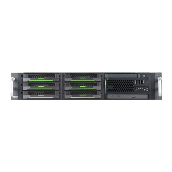
- Page 1 PRIMERGY RX300 S5 Operating manual Edition september 2009...
-
Page 2: Copyright And Trademarks
Gesellschaft für Technik-Dokumentation mbH www.cognitas.de Copyright and Trademarks Copyright © 2009 Fujitsu Technology Solutions GmbH. All rights reserved. Delivery subject to availability. The right to technical modification is reserved. All hardware and software names used are trade names and/or trademarks of their respective... -
Page 3: Table Of Contents
Contents Preface ......7 Concept and target groups for this manual . - Page 4 Contents 4.4.2 Using cable ties ......56 Instructions for connecting/disconnecting cables ..57 Starting up and operation .
- Page 5 Contents Added drive reported as defective ....83 7.10 Error message on screen ....83 CSS components .
-
Page 7: Preface
The system was developed specifically for configurations with multiple servers (clusters), front-end solutions, e-commerce applications and ERP solutions. The PRIMERGY RX300 S5 is ideal for applications and operational areas that require maximum scalability, performance and availability in a space-saving rack cabinet. -
Page 8: Documentation Overview
Documentation overview Preface Documentation overview More information on your PRIMERGY RX300 S5 can be found in the following documents: – "Quick Start Hardware - PRIMERGY RX300 S5" leaflet (only included as a printed copy) – "Quick Start Software - Quick Installation Guide" DVD booklet (only included with the PRIMERGY ServerView Suite as a printed copy) –... - Page 9 The PDF files of the manuals can also be downloaded free of charge from the Internet. The overview page showing the online documentation available on the Internet can be found using the URL: http://manuals.ts.fujitsu.com. The PRIMERGY server documentation can be accessed using the Industry standard servers navigation option. Further sources of information: –...
-
Page 10: Features
Preface Features Customer Self Service (CSS) The Fujitsu Technology Solutions Customer Self Service (CSS) concept enables you to identify and replace the affected component yourself in the case of certain error scenarios. In the CSS concept, you can replace the following components yourself in the event of an error: –... - Page 11 (e.g. drive encryption using Windows Bitlocker Drive Encryption). The TPM is activated via the BIOS system (for more information, refer to the Fujitsu Technology Solutions BIOS manual). CAUTION! – When using the TPM, note the program descriptions provided by the third party manufacturers.
- Page 12 Features Preface Fujitsu Technology Solutions offers a unique patented solution to deliver the highest possible bandwidth with four PCIe Gen2 x8 slots: two of the four PCIe Gen2 x4 slots can each be used as PCIe Gen2 x8 slots if the neighboring slot is free.
- Page 13 Preface Features Hard disk drives The server is available in the following drive configurations: ● 6*3.5-inch SAS/SATA hard disk drives: up to six (2x3) HDD modules, each with a 3.5-inch SAS/SATA hard disk drive with a maximum height of 1 inch. Slot for an optional 3.5-inch DAT or RDX drive.
- Page 14 Features Preface The module is connected to the SAS/SATA backplane without cables. This allows HDD modules to be simply plugged in or pulled out (for further details see section "Hot-plug hard disk drives" on page 88). The hard disk subsystem is designed for SAS/SATA, each with one channel for each hard disk drive.
- Page 15 Preface Features Accessible drives/components A number of mounting locations are available: – One 3.5-inch slimline bay for an optional Local Service Module: ServerView Local Service Display (LSD) or ServerView Local Service Panel (LSP) – One 3.5-inch slimline bay for an optional optical drive For a configuration with 3.5-inch HDD modules, an optional DAT or RDX drive can be installed in the right-hand drive cage.
- Page 16 Features Preface Power supply In its basic configuration, the server has a hot-pluggable power supply unit that adjusts automatically to any power voltage in the range from 100 V to 240 V. As an option, the power supply can be expanded with an extra power supply unit to create a redundant power supply.
- Page 17 ASR&R (Automatic Server Reconfiguration and Restart) restarts the system in the event of an error and automatically "hides" the defective system components. The PDA (Prefailure Detection and Analysing) technology from Fujitsu Technology Solutions analyzes and monitors all components that are critical for system reliability.
- Page 18 Features Preface iRMC S2 with integrated service LAN port The features of the iRMC S2 Advanced Video Redirection and Remote Storage are available as an option. The iRMC S2 (integrated Remote Management Controller) is a BMC with integrated service LAN port and expanded functionality that was previously only available with additional plug-in cards.
- Page 19 Server management is implemented using the ServerView Operations Manager supplied combined with PDA (Prefailure Detection and Analysis) technology from Fujitsu Technology Solutions. PDA reports the threat of a system error or overload at an early stage, allowing preventive measures to be taken.
- Page 20 BIOS update. With the iRMC S2 (integrated Remote Management Controller) on the system board, the PRIMERGY RX300 S5 server can also be maintained and serviced remotely. This enables remote diagnosis for system analysis, remote configuration and remote restart should the operating system or hardware fail.
- Page 21 ServerView Remote Management ServerView Remote Management is the remote management solution from Fujitsu Technology Solutions for PRIMERGY servers. ServerView Remote Management and the relevant hardware components integrated on the system board allow remote monitoring and maintenance as well as fast restoration of operation in the event of errors.
-
Page 22: Notational Conventions
Notational conventions Preface Notational conventions The following notational conventions are used in this manual: Text in italics indicates commands or menu items. "Quotation marks" indicate names of chapters and terms that are being emphasized. Ê describes activities that must be performed in the order shown. -
Page 23: Technical Data
Preface Technical data Technical data Electrical data (hot-plug power supply unit) Rated voltage range 100 V - 240 V Frequency 50 Hz - 60 Hz Rated current with basic configuration 4.2 A - 1.4 A / 100 V - 240 V Max. - Page 24 Technical data Preface Mechanical values Width 445 mm Depth 770 mm Height 85.9 mm or 2HU Installation depth in rack 735 mm Cable depth in rack 100 mm (1000 mm rack recommended) Weight Approx. 25 kg (depending on configuration). Ventilation clearance At least 200 mm on the front and rear.
-
Page 25: Installation Steps, Overview
Installation steps, overview This chapter contains an overview of the steps necessary to install your server. Links take you to sections where you can find more detailed information about the respective steps: Ê First of all, carefully read the safety instructions in "Important information"... - Page 26 Installation steps, overview Ê Configure the server and install the desired operating system and applications. The following options are available: – Remote installation with the ServerView Installation Manager: With the PRIMERGY ServerView Suite DVD 1 provided, you can configure the server and install the operating system in a convenient manner.
-
Page 27: Important Information
Important information In this chapter you will find essential information regarding safety when working on your server. Safety instructions The following safety instructions are also provided in the manual "Safety notes and other important information". This device meets the relevant safety regulations for IT equipment. If you have any questions about whether you can install the server in the intended environment, please contact your sales outlet or our customer service team. - Page 28 Safety instructions Important information Before starting up CAUTION! ● During installation and before operating the device, observe the instructions on environmental conditions for your device (see section "Technical data" on page 23). ● If the server has been moved from a cold environment, condensation may form both inside and on the outside of the machine.
- Page 29 Important information Safety instructions CAUTION! ● Ensure that the power sockets on the device and the grounded shockproof sockets are freely accessible. The On/Off button or the main power switch (if present) does not ● isolate the device from the mains power supply. To disconnect it completely from the mains power supply, unplug all network power plugs from the grounded shockproof sockets.
- Page 30 Safety instructions Important information CAUTION! ● Proper operation of the system (in accordance with IEC 60950-1/ EN 60950-1) is only ensured if the casing is completely assembled and the rear covers for the installation slots have been fitted (electric shock, cooling, fire protection, interference suppression). ●...
- Page 31 Important information Safety instructions Working with CDs/DVDs and CD/DVD drives When working with devices with CD/DVD drives, these instructions must be followed. CAUTION! Only use CDs/DVDs that are in perfect condition in your server's ● CD/DVD drive, in order to prevent data loss, equipment damage and injury.
- Page 32 Safety instructions Important information Batteries CAUTION! ● Incorrect replacement of batteries may lead to a risk of explosion. The batteries may only be replaced with identical batteries or with a type recommended by the manufacturer (see the technical manual for the system board).
- Page 33 Important information Safety instructions Modules with Electrostatic-Sensitive Devices Modules with electrostatic-sensitive devices are identified by the following sticker: Figure 5: ESD label When you handle components fitted with ESDs, you must always observe the following points: Switch off the system and remove the power plugs from the power outlets ●...
-
Page 34: Energy Star
ENERGY STAR Important information Other important information: ● When cleaning the device, please observe the relevant notes in section "Cleaning the server" on page Keep this operating manual and the other documentation (such as the ● Technical Manual, DVD) close to the device. All documentation must be included if the equipment is passed on to a third party. -
Page 35: Fcc Class A Compliance Statement
● Consult the dealer or an experienced radio/TV technician for help. Fujitsu Technology Solutions is not responsible for any radio or television interference caused by unauthorized modifications of this equipment or the substitution or attachment of connecting cables and equipment other than those specified by Fujitsu Technology Solutions. -
Page 36: Transporting The Server
Transporting the server Important information WARNING: This is a class A product. In a domestic environment this product may cause radio interference in which case the user may be required to take adequate measures. Transporting the server CAUTION! Only transport the server in its original packaging or in packaging that protects it from impacts and jolts. -
Page 37: Notes On Installing In The Rack
Important information Notes on installing in the rack Notes on installing in the rack CAUTION! ● For safety reasons, at least two people are required to install the rack model because of its weight and size. Never lift the server into the rack using the handles on the front panel. ●... -
Page 38: Environmental Protection
Important information Environmental protection Environmentally-friendly product design and development This product has been designed in accordance with the Fujitsu Technology Solutions standard for "environmentally friendly product design and development". This means that key factors such as durability, selection and labeling of materials, emissions, packaging, ease of dismantling and recycling have been taken into account. - Page 39 Details regarding the return and recycling of devices and consumables within Europe can also be found in the "Returning used devices" manual, via your local Fujitsu Technology Solutions branch or from our recycling center in Paderborn: Fujitsu Technology Solutions Recycling Center D-33106 Paderborn Tel.
-
Page 41: Hardware Installation
Hardware installation CAUTION! ● Follow the safety instructions in the chapter "Important information" on page Do not expose the server to extreme environmental conditions (see ● "Technical data" on page 23). Protect the server from dust, humidity and heat. ● Make sure that the server is acclimatized for the time indicated in this table before putting it into operation. -
Page 42: Unpacking The Server
Unpacking the server Hardware installation Unpacking the server CAUTION! Follow the safety instructions in chapter "Important information" on page The server must always be lifted or carried by at least two people. Do not unpack the server until it is at its installation location. Ê... -
Page 43: Installing/Removing The Server In/From The Rack
The power is supplied via the multiple socket outlets fitted in the rack. PRIMECENTER/DataCenter Rack The main features of the rack systems from Fujitsu Technology Solutions are as follows: – Support systems that can be mounted without tools The support systems have a linear alignment feature to ensure that they can be adjusted to different rack depths. - Page 44 Installing/removing the server in/from the rack Hardware installation Installation of the cable management is described in detail in the Technical Manual for the respective rack. 3rd party racks Certain general conditions must be met: – Installation dimensions (see the dimensions shown in figure 6 on page 45): Front of rack...
- Page 45 Hardware installation Installing/removing the server in/from the rack +/- 1,6mm Figure 6: Mechanical requirements Operating manual RX300 S5...
- Page 46 Installing/removing the server in/from the rack Hardware installation – You must ensure that the safety mechanisms on the server, e.g. stoppers or retaining systems, are functioning correctly. – The shape of the rack support uprights must ensure that the support systems can be bolted to the front.
-
Page 47: Installation In Primecenter/Datacenter Rack
Hardware installation Installing/removing the server in/from the rack 4.2.2 Installation in PRIMECENTER/DataCenter Rack For installation in a PRIMECENTER/DataCenter rack, the following parts are required: – Support bracket – One support system on the left and one on the right General information is provided in the Technical Manual for the PRIMECENTER and/or DataCenter Rack. - Page 48 Installing/removing the server in/from the rack Hardware installation Removing the outer telescopic rail Figure 8: Removing the outer telescopic rail Ê Extend the telescopic rail fully (1). Ê Unlock the outer telescopic rail and remove it. With fully-extendable rails (a): Press the locking lever to release the server rail.
- Page 49 Hardware installation Installing/removing the server in/from the rack Installing the support systems Figure 9: Fit the left support system in the PRIMECENTER/DataCenter rack Ê Position the left support system in the support bracket (insert retaining bolts) - see (1). Ê Clamp the left-hand support system (2) between the front left support upright and the support bracket by pressing the support system together, positioning it on the front support upright and releasing it again.
- Page 50 Installing/removing the server in/from the rack Hardware installation CAUTION! Ensure that the safety lock has been inserted before the server is inserted! Ê Repeat the above steps for the right-hand support system (with the front and rear right support uprights). Ê...
- Page 51 Hardware installation Installing/removing the server in/from the rack Inserting the server Figure 11: Inserting the server CAUTION! Ensure that the safety lock has been inserted before the server is inserted (see figure 9 on page 49). CAUTION! At least two people are needed to position the server in the rack. Ê...
-
Page 52: Installation In 3Rd Party Racks
Hardware installation 4.2.3 Installation in 3rd party racks The support systems from Fujitsu Technology Solutions are suitable for use in any 3rd party racks for standard servers (installation depth 735 - 770 mm without restrictions. Ê Refer to the manual from the rack manufacturer for details of the mechanical installation and the climatic conditions. -
Page 53: Connecting Devices To The Server
Hardware installation Connecting devices to the server Connecting devices to the server The ports for external devices are on the rear of the server. The additional ports available on your server depend on the options and expansion cards installed. The standard ports (figure 12) are marked with symbols, and some are color- coded:... - Page 54 Connecting devices to the server Hardware installation Three additional USB ports (1) are located on the front of the server (figure 13): 1 1 1 Figure 13: Front side: additional USB ports If components with large power requirements (e.g. external USB hard disk drives) are connected simultaneously, these USB ports may be switched off.
-
Page 55: Connecting The Server To The Mains
Hardware installation Connecting the server to the mains Connecting the server to the mains In its basic configuration level the server has a hot-plug power supply unit. A second hot-plug power supply unit can be added to ensure a redundant power supply. -
Page 56: Rx300 S5
Connecting the server to the mains Hardware installation 4.4.2 Using cable ties As an option, you can secure the power cable using a cable tie to ensure that the insulated connector cannot be disconnected from the server accidentally. The cable tie is included in the accessories pack that is delivered together with the server. -
Page 57: Instructions For Connecting/Disconnecting Cables
Hardware installation Instructions for connecting/disconnecting cables Instructions for connecting/disconnecting cables CAUTION! Be sure to read the documentation for the peripheral devices before connecting them. Do not connect or disconnect data cables during a thunderstorm. When removing a cable, always hold it by the plug. Never unplug a cable by pulling at the cable itself. -
Page 59: Starting Up And Operation
Starting up and operation CAUTION! Please note the safety instructions in chapter "Important information" on page 27 Controls and indicators 5.1.1 Front of server Figure 16: Front side: indicators and controls 1 3 x USB ports Hard disk activity indicator 2 Monitor port (optional) Global Error indicator 3 Reset button... -
Page 60: Controls
Controls and indicators Starting up and operation 5.1.1.1 Controls On/Off button When the system is switched off, it can be switched on again by pressing the On/Off button. When the system is operating, pressing the On/Off button will switch off the system. The On/Off button does not disconnect the server from the mains voltage. -
Page 61: Indicators On The Control Panel
Starting up and operation Controls and indicators 5.1.1.2 Indicators on the control panel Power-on indicator (two colors) Lights up green when the server is switched ON. Lights up orange when the server is switched OFF, but mains voltage is present (standby mode). Hard disk activity indicator (green) Lights up green when an internal drive (HDD or backup drive) is being accessed. - Page 62 Controls and indicators Starting up and operation CSS indicator (yellow) – Lights up yellow if a prefailure event was detected for a CSS component that you can fix yourself (for reasons of precaution) with the CSS concept. – Flashes yellow if an error was detected that you can fix yourself with the CSS concept.
-
Page 63: Indicators On The Drives
Starting up and operation Controls and indicators 5.1.1.3 Indicators on the drives DVD drive activity indicator Lights up green when the storage medium is being accessed. Indicators on the optional USB magnetic tape drive Figure 17: USB magnetic tape drive Tape indicator;... - Page 64 Controls and indicators Starting up and operation Indicators on the optional RDX drive Figure 18: RDX drive The access indicator is located on the medium. Medium indicator Ready Flashing Active Operating manual RX300 S5...
- Page 65 Starting up and operation Controls and indicators Hard disk drive indicators Figure 19: Indicators on the 3.5 inch and 2.5 inch HDD modules 1 LED HDD BUSY green – Lights up: HDD in active phase – Does not light: HDD inactive (drive inactive) 2 LED HDD FAULT (orange) orange...
-
Page 66: Rear Of Server
Controls and indicators Starting up and operation 5.1.2 Rear of server CSS, Global Error and ID indicators Figure 20: Indicators on the connection panel: Global Error/CSS/ID indicator Global Error/CSS/ID indicator (orange, yellow and blue) Global Error indicator (orange) – Lights up orange if a prefailure event has been detected that requires (precautionary) service intervention. - Page 67 Starting up and operation Controls and indicators CSS indicator (yellow) – Lights up yellow if a prefailure event was detected for a CSS component that you can fix yourself (for reasons of precaution) with the CSS concept. – Flashes yellow if an error was detected that you can fix yourself with the CSS concept.
- Page 68 Controls and indicators Starting up and operation LAN indicators 1 2 3 4 Figure 21: Indicators on the connection panel: LAN indicators LAN activity indicator (service LAN) Lights up green if a LAN connection exists. Does not light up if no LAN connection exists. Flashes green when a LAN transfer is in progress.
- Page 69 Starting up and operation Controls and indicators Indicators on the hot-plug power supply unit Figure 22: Indicator on hot-plug power supply unit Indicator on hot-plug power supply unit (two colors) Flashes green when the server is switched off, but mains voltage is present (standby mode).
-
Page 70: Indicators Of The Hot-Plug Fans
Controls and indicators Starting up and operation 5.1.3 Indicators of the hot-plug fans A bicolor status indicator (LED on the system board) is assigned to each fan. The status indicators are not visible unless the housing is open. The respective LED is set with commands in Server Management. -
Page 71: Switching The Server On And Off
Starting up and operation Switching the server on and off Switching the server on and off CAUTION! It nothing appears on the screen but flickering stripes after switching on the server, switch the server off immediately (see chapter "Troubleshooting and tips" on page 79). - Page 72 Switching the server on and off Starting up and operation If the operating system does not switch the server off automatically, press the On/Off button for at least four seconds and/or send a corresponding control signal. Other On/Off options Besides the On/Off button, the server can be switched ON and OFF in the following ways: –...
-
Page 73: Configuring The Server
Starting up and operation Configuring the server Configuring the server This section contains information about configuring the server and installing the operating system. 5.3.1 Configuring the SAS/SATA RAID controller The server has a SAS/SATA RAID controller with "Integrated Mirroring Enhanced" functionality or "MegaRAID functionality". You can configure the SAS/SATA RAID controller either before or during installation with the ServerView Installation Manager. -
Page 74: Configuring The Server And Installing The Operating System With The Serverview Installation Manager
Configuring the server Starting up and operation 5.3.2 Configuring the server and installing the operating system with the ServerView Installation Manager Using the ServerView Installation Manager on the PRIMERGY ServerView Suite DVD 1 provided, you can conveniently configure the server and install the operating system. -
Page 75: Configuring The Server And Installing The Operating System Without The Serverview Installation Manager
Starting up and operation Configuring the server 5.3.3 Configuring the server and installing the operating system without the ServerView Installation Manager Configuring SAS/SATA RAID controller with "Integrated Mirroring Enhanced" Configure the controller as described in section "Configuring the SAS/SATA RAID controller" on page Configuring SAS/SATA RAID controller with "MegaRAID functionality"... -
Page 76: Cleaning The Server
Cleaning the server Starting up and operation Cleaning the server CAUTION! Switch the server off and disconnect the power plugs from the grounded shockproof sockets. Do not clean any interior parts yourself; leave this job to a service technician. Do not use any cleaning agents that contain abrasives or may corrode plastic. -
Page 77: Property And Data Protection
Property and data protection The lockable rack door protects the server against unauthorized access. To protect your system and data internally against unauthorized access, you can use the BIOS Setup security functions. BIOS Setup security functions The Security menu in BIOS Setup offers various options for protecting your data from unauthorized access. -
Page 79: Troubleshooting And Tips
Troubleshooting and tips CAUTION! Follow the safety instructions in the "Safety notes and other important information" manual and in chapter "Important information" on page If a fault occurs, attempt to resolve it using the measures described: – in this chapter, –... -
Page 80: Server Switches Itself Off
Server switches itself off Troubleshooting and tips Server switches itself off Server Management has detected an error Ê Check the error list or the ErrorLog file in the ServerView Operations Manager, and attempt to eliminate the error. Screen remains blank Monitor is switched off Ê... -
Page 81: Flickering Stripes On Monitor Screen
Troubleshooting and tips Flickering stripes on monitor screen Flickering stripes on monitor screen CAUTION! Switch off the server immediately. Risk of damaging the server. Monitor does not support the set horizontal frequency Ê Find out which horizontal frequency your monitor screen supports. You will find the horizontal frequency (also known as line frequency or horizontal deflection frequency) in the documentation for your monitor. -
Page 82: Incorrect Date And Time
Incorrect date and time Troubleshooting and tips Incorrect date and time Ê Set the date and time in the operating system or in the BIOS Setup under the Main menu, using System Date and System Time respectively. Note that the operating system may affect the system time. For example, the operating system time may deviate from the system time under Linux, and would overwrite the system time in the default setting on shutdown. -
Page 83: Added Drive Reported As Defective
Troubleshooting and tips Added drive reported as defective Added drive reported as defective RAID controller is not configured for this drive The drive was probably installed when the system was switched off. Ê Reconfigure the RAID controller for the drive using the corresponding utility. Information is provided in the documentation for the RAID controller. -
Page 85: Css Components
CAUTION! Follow the safety instructions in the chapter "Important information" on page In the PRIMERGY RX300 S5 server, the following components are considered to be CSS components: – Hot-plug components – Hot-plug power supply units – Hot-plug hard disk drives –... -
Page 86: Hot-Plug Components
Hot-plug components CSS components Hot-plug components This section describes how to handle hot-plug components and how to modify your server hardware (e.g. adding/replacing hot-plug power supply units or hot- plug HDD modules). The hot-plug procedure increases the availability of system operation and guarantees a high degree of data integrity and failsafe performance. -
Page 87: Replacing The Hot-Plug Power Supply Unit
CSS components Hot-plug components 8.1.1.3 Replacing the hot-plug power supply unit Figure 23: Unlocking and removing the power supply unit CAUTION! Before replacing a non defective power supply unit in a non-redundant configuration (only one power supply unit present) the server must be switched OFF. -
Page 88: Hot-Plug Hard Disk Drives
8.1.2 Hot-plug hard disk drives The hard disk drives which can be ordered for the PRIMERGY RX300 S5 are supplied already mounted in an installation frame so that defective hard disk drives can be replaced and new drives can be added during operation. The hard disk drive and installation frame together make up the HDD module. -
Page 89: Inch Hdd Module And Dummy Module
CSS components Hot-plug components 8.1.2.1 3.5-inch HDD module and dummy module Figure 24: 3.5-inch HDD module and dummy module Dummy module Tabs for unlocking the dummy module HDD module (installation frame with hard disk drive installed) Indicators HDD Busy (LED green) HDD Fault (LED orange) For description see section "Hard disk drive indicators"... -
Page 90: Inch Hdd Module And Dummy Module
Hot-plug components CSS components 8.1.2.2 2.5-inch HDD module and dummy module Figure 25: 2.5-inch HDD module and dummy module Dummy module Tabs for unlocking the dummy module HDD module (installation frame with hard disk drive installed) Indicators HDD Busy (LED green) HDD Fault (LED orange) For description see section "Hard disk drive indicators"... -
Page 91: Handling Hard Disk Drives And Hdd Modules
CSS components Hot-plug components 8.1.2.3 Handling hard disk drives and HDD modules Hard disk drives incorporated in the HDD modules are highly sensitive electromagnetic devices and must be handled with great care. Incorrect handling can cause partial or total failure of the hard disk drives. These failures can result in data errors and to a loss of data or to total corruption of the hard disk drive. - Page 92 Hot-plug components CSS components Figure 26: Removing/installing the dummy module (example: 3.5-inch dummy module) Ê Press both tabs on the dummy module together until the locking mechanism disengages (1). Ê Pull the dummy module out of the bay (2). To install a dummy module, follow the same procedure in reverse order. CAUTION! Store the dummy module in a safe place.
-
Page 93: Installing The Hdd Module
CSS components Hot-plug components 8.1.2.5 Installing the HDD module Unlocking the HDD module Figure 27: Unlocking the 3.5-inch and 2.5-inch HDD modules Ê Release the locking mechanism by pressing the locking button (1). Ê Push the handle of the HDD module fully in the direction of the arrow (2). The HDD module is now unlocked. - Page 94 Hot-plug components CSS components Installing the HDD module Figure 28: Installing the 2.5-inch and 3.5-inch HDD modules Ê Unlock the HDD module as described in section "Unlocking the HDD module" on page Ê Carefully push the HDD module into the empty slot (1) until it stops. Ê...
-
Page 95: Removing The Hdd Module
CSS components Hot-plug components 8.1.2.6 Removing the HDD module CAUTION! ● Only remove a HDD module during operation if the drive is not currently being accessed. Observe the control LEDs for the corresponding HDD modules (see "Hard disk drive indicators" on page 65). - Page 96 Hot-plug components CSS components Ê Install the new HDD module, as described in "Installing the HDD module" on page CAUTION! If you have removed a HDD module and do not install a new one in its place, put the dummy module back in its place for cooling, to comply with EMC regulations (regulations regarding electromagnetic compatibility), and for protection against fire.
-
Page 97: Replacing The Hot-Plug Fan Modules
CSS components Hot-plug components 8.1.3 Replacing the hot-plug fan modules CAUTION! The actions described in this section may only be performed by personnel with the appropriate technical training. Any unauthorized openings and improper repairs could expose the user to risks (electric shock, fire hazards) and could also damage the equipment. -
Page 98: Replacing The Fan Modules
Hot-plug components CSS components 8.1.3.1 Replacing the fan modules Ê Remove the housing cover (see section "Opening/closing the housing" on page 106). Figure 29: Arrangement of fans and the corresponding indicators Ê Use the indicator (lights up orange) to identify the defective fan. The position of the indicators is shown by arrows in figure Operating manual... - Page 99 CSS components Hot-plug components Figure 30: Removing the fans (example: fan 1) Ê Pull the green lever on the fan handle in the direction of the arrow (1) to release the locking mechanism, and pull out the handle (2). Ê Pull the fan out of its mounting location by its handle. Ê...
-
Page 100: Non-Hot-Plug Components
Non-hot-plug components CSS components Non-hot-plug components CAUTION! The actions described in this section may only be performed by personnel with the appropriate technical training. (The device can be seriously damaged if it is opened without authorization or if repairs are attempted by untrained personnel.) Please observe the safety information in chapter "Important information"... -
Page 101: Replacing A Memory Module
CSS components Non-hot-plug components 8.2.1 Replacing a memory module Ê Remove the housing cover (see section "Opening/closing the housing" on page 106). The slots for the memory modules can be found under the air cowl. 8.2.1.1 Removing the air cowl Figure 31: Removing the air cowl If you have installed an SAS/SATA RAID controller with a BBU: pay attention to the BBU cable (see circle) when lifting off the air cowl! If you... -
Page 102: Removing A Defective Memory Module
Non-hot-plug components CSS components 8.2.1.2 Removing a defective memory module Figure 32: Removing a memory module Ê Press the holders on either side of the mounting location concerned outward (1). Ê Pull the memory module out of the slot (2). 8.2.1.3 Installing a new memory module CAUTION! -
Page 103: Replacing The Air Cowl And Closing The Server
CSS components Non-hot-plug components 8.2.1.4 Replacing the air cowl and closing the server Ê Insert the air cowl in the server. If an SAS/SATA RAID controller is installed and you disconnected the BBU cable when you removed the air cowl: Ê... -
Page 104: Replacing An Expansion Card
Non-hot-plug components CSS components 8.2.2 Replacing an expansion card Ê The illuminated orange indicator shows which is the slot for the defective expansion card. Figure 34: Removing the expansion card Ê If necessary, disconnect the cables from the defective expansion card. Ê... - Page 105 CSS components Non-hot-plug components Figure 35: Installing an expansion card Ê Carefully press the new expansion card into the correct slot on the system board (arrows) until it clicks into place. Ê Secure the expansion card with the screw (circle). Ê...
-
Page 106: Opening/Closing The Housing
Opening/closing the housing CSS components Opening/closing the housing CAUTION! The actions described in this section may only be performed by personnel with the appropriate technical training. If the fan cover is opened without authorization or if repairs are carried out incorrectly, the user may be exposed to danger (electric shock, risk of fire), or the device may be damaged.The safety instructions in chapter"Important... -
Page 107: Index
Index cables 3rd party rack external devices installing in consumables requirements control panel controls cooling accessible drives fans correcting faults DVD writer magnetic tape drive fans acclimatization time 41, CSS indicator 59, 62, Advanced Video Redirection articulated cable guide ASR&R data protection availability data security... - Page 108 Index ENERGY STAR FCC statement environment class features environmental conditions flash EPROM environmental protection error Global Error indicator 59, 61, drifting display on monitor graphics card drive “dead” drive defective incorrect date hard disk activity indicator 59, incorrect time hard disk drive no display on monitor handling power-on indicator does not...
- Page 109 Index LAN activity LAN transfer rate NMI button 59, magnetic tape drive 63, noise level on power supply unit notational conventions on the server operation On/Off button 59, system error 61, online replacement information, additional opening installing housing server 43, operation installing in overload...
- Page 110 Index data protection rack dimensions requirements electrical data RAID controller is not configured for environmental conditions this drive fitting in rack recycling devices hot-plug power supply unit redundancy indicators fans installing 43, power supply LAN port regulations and standards NMI button Remote Storage noise level removing...
- Page 111 Index server support bracket switch off time, defining switch on time, defining switching off, server switching on, server system fans system board PRIMERGY Diagnostic LED system does not boot system fans redundant target group technical data telescopic rail time, incorrect tips touch point service...