Kenwood PKT-23 Instruction Manual
Uhf fm transceiver
Hide thumbs
Also See for PKT-23:
- Instruction manual (32 pages) ,
- Easy programming instructions (15 pages) ,
- Specifications (2 pages)

Related Manuals for Kenwood PKT-23


Summary of Contents for Kenwood PKT-23
-
Page 1: Instruction Manual
INSTRUCTION MANUAL UHF FM TRANSCEIVER PKT-23 © B62-2576-00 (K) 09 08 07 06 05 04 03 02 01 00... -
Page 2: Thank You
Thank You We are grateful for your purchase of this KENWOOD product and welcome you to the Business Radio Service (BRS). Your KENWOOD 2-way Business Radio is called a “transceiver”, meaning “transmitter & receiver”. We believe this easy-to-use transceiver will provide you with dependable and reliable communications. - Page 3 FCC LICense InFormaTIon Your KENWOOD transceiver operates on communications frequencies which are subject to FCC (Federal Communications Commission) Rules & Regulations. FCC Rules require that all operators using Private Land Mobile radio frequencies obtain a radio license before operating their equipment.
- Page 4 For information on Li-ion battery recycling in your area, call (toll free) 1-800-8-BATTERY (1-800-822-8837). KENWOOD’s involvement in this program is part of our commitment to preserve our environment and conserve our natural resources.
-
Page 5: Notices To The User
Do not charge the transceiver and battery pack when they are wet. • Ensure that there are no metallic items located between the transceiver and the battery pack. • Do not use options not specified by KENWOOD. • If any transceiver part is damaged, do not touch the damaged parts. •... - Page 6 If an abnormal odor or smoke is detected coming from the transceiver, switch the transceiver power off immediately, remove the battery pack from the transceiver, and contact your KENWOOD dealer. • Use of the transceiver while you are driving may be against traffic laws.
- Page 7 Information concerning the battery pack: The battery pack includes flammable objects such as organic solvent. Mishandling may cause the battery to rupture producing flames or extreme heat, deteriorate, or cause other forms of damage to the battery. Please observe the following prohibitive matters.
- Page 8 Use only the specified charger and observe charging • requirements! If the battery is charged in unspecified conditions (under high temperature over the regulated value, excessive high voltage or current over regulated value, or with a remodeled charger), it may overcharge or an abnormal chemical reaction may occur.
- Page 9 The battery may generate heat or smoke, rupture, or burst into flame. Firmware Copyrights The title to and ownership of copyrights for firmware embedded in KENWOOD product memories are reserved for JVC KENWOOD Corporation. viii...
-
Page 10: Table Of Contents
CONTENTS unPaCkInG anD CheCkInG eQuIPmenT ......1 PreParaTIon ............2 orIenTaTIon ............7 BasIC oPeraTIons ........... 9 VoICe oPeraTeD TransmIssIon (VoX) ......11 ChanneL seTuP moDe ..........12 keY assIGnmenT moDe ..........18 TrouBLeshooTInG GuIDe ......... 21 aLL reseT moDe ............. 22 unPaCkInG anD CheCkInG eQuIPmenT Carefully unpack the transceiver. -
Page 11: Preparation
PreParaTIon CharGInG The BaTTerY PaCk The battery pack is not charged at the factory; charge it before use. Average battery pack life (calculated using 5% transmit time, 5% receive time, and 90% standby time) is 15 hours. Note: ◆ The ambient temperature should be between 32°F and 104°F (0°C and 40°C) while charging is in progress. - Page 12 3 When charging is complete, the LED indicator turns off. • It takes approximately 4 hours to Indicator charge the battery pack. n Charging with the ksC-44Cr Charger 1 Plug the AC adapter cable into the jack located on the bottom of the charger. 2 Plug the AC adapter into an AC outlet.
- Page 13 rePLaCInG The BaTTerY PaCk Replace an expired battery pack with a newly purchased KNB-71L battery pack. ◆ Do not disassemble the battery pack. ◆ Be sure to follow local laws concerning the disposal of battery packs. 1 Pull back the battery pack latch, then remove the battery cover from the transceiver.
- Page 14 Red cable (right side) 4 Insert the connector of the new battery pack into the PCB terminal by pressing down on it. • Match the direction of the connector and insert it vertically. 5 Pull back the battery pack latch, then insert the battery pack into position.
- Page 15 InsTaLLInG The BeLT CLIP If necessary, attach the belt clip using the two supplied M3 x 6 mm screws (with washers). Note: If the belt clip is not installed, its mounting location may get hot during continuous transmission or when left sitting in a hot environment. Do not use glue which is designed to prevent screw loosening when installing the belt clip, as it may cause damage to the transceiver.
-
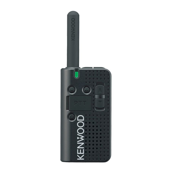
Page 16: Orientation
orIenTaTIon ① ② 3.5 mm phone jack Connect the earphone/ microphone plug to this jack. Micro USB jack (B Type) Connect a USB cable to this jack to charge the transceiver battery pack. Antenna PF-1 key Press or hold this key for 1 second to activate its programmable functions. -
Page 17: Led Indicator
LED indicator Refer to the “LED INDICATOR STATUS” table on page 10. Antenna ⑥ PF-2 key Press this key to toggle the ⑦ function of the Up/Down keys ⑧ between Volume Adjustment mode and Channel Select mode. Hold this key for 1 second Microphone to activate its programmable function. -
Page 18: Basic Operations
BasIC oPeraTIons Power anD VoLume 1 Hold the Power switch for approximately 1 second to switch the transceiver power ON. • A beep sounds and the LED indicator blinks blue a number of times as described in the “BATTERY LEVEL GUIDE” table on page 10. -
Page 19: Battery Level
◆ Even when setting the volume to 0, the transceiver will continue to emit beep sounds and channel announcements. ◆ Continuously transmitting when the transceiver becomes too hot will cause the output power to decrease and may eventually stop transmission. Stop transmitting for a while to allow the transceiver to cool down. -
Page 20: Voice Operated Transmission (Vox)
VoICe oPeraTeD TransmIssIon (VoX) VOX operation allows you to transmit hands-free. VOX can only be used if you are using a supported clip microphone with earphone/hanger. This function can be turned off for specific channels. To activate VOX and set the VOX Gain level, perform the following steps: 1 Connect the microphone with earphone/hanger to the transceiver. -
Page 21: Channel Setup Mode
ChanneL seTuP moDe This transceiver allows you to reprogram each of the channels with different frequencies and QT (Quiet Talk)/ DQT (Digital Quiet Talk) settings. The table below lists the default channel settings. Channel Table Frequency QT/DQT Setting Number Number 464.5500 MHz 67.0 Hz 467.9250 MHz... - Page 22 5 Press the PTT switch to save the setting and switch to the QT/ DQT setting. • A beep will sound and the transceiver announces “QT”. 6 Press the Up/Down key to select QT or DQT, then press the PTT switch to confirm the selection. 7 Press the Up/Down key to increment/ decrement the QT/ DQT number, to select the new value.
- Page 23 Operating Operating Table Number Table Number Frequency (MHz) Frequency (MHz) 461.2625 462.4875 461.2875 462.5125 461.3125 467.1875 461.3375 467.4625 461.3625 467.4875 462.7625 467.5125 462.7875 451.1875 462.8125 451.2375 462.8375 451.2875 462.8625 451.3375 462.8875 451.4375 462.9125 451.5375 464.4875 451.6375 464.5125 452.3125 464.5375 452.5375 464.5625 452.4125 466.0375...
-
Page 24: Quiet Talk/Digital Quiet Talk
QuIeT TaLk (QT)/ DIGITaL QuIeT TaLk (DQT) Quiet Talk (QT) and Digital Quiet Talk (DQT) are functions that reject undesired signals on your channel. You will hear a call only when you receive a signal that contains a matching QT tone or DQT code. - Page 25 DQT Channel Settings: Number Code Number Code Number Code Number Code D023N D223N D503N D047I D025N D226N D506N D051I D026N D243N D516N D054I D031N D244N D532N D065I D032N D245N D546N D071I D043N D251N D565N D072I D047N D261N D606N D073I D051N D263N D612N D074I...
- Page 26 Number Code Number Code Number Code Number Code D261I D411I D546I D731I D263I D412I D565I D732I D265I D413I D606I D734I D271I D423I D612I D743I D306I D431I D624I D754I D311I D432I D627I D645I D315I D445I D631I D023N D331I D464I D632I D023N D343I D465I D654I...
-
Page 27: Key Assignment Mode
keY assIGnmenT moDe This transceiver allows you to reprogram the PF-1 key (press/ hold) and PF-2 key (hold only) with any of the functions listed in the table below. Explanations on the use of each function are provided under “PROGRAMMABLE FUNCTIONS”, on page 19. Table Number Function Name None (no function) -
Page 28: Programmable Functions
4 Press the PF-1 key or hold the PF-1 or PF-2 key to program the new function onto the desired key. A tone sounds after pressing the PF-1 key, confirming that the • function has been stored to the PF-1 press operation. •... -
Page 29: Squelch Off
n Squelch Off Press this key to hear background noise. Press the key again to return to normal operation. n Super Lock-C Press and hold this key for 4 seconds to lock the transceiver keys. Super Lock-C locks the transceiver keys to prevent accidental operation. -
Page 30: Troubleshooting Guide
TrouBLeshooTInG GuIDe Problem Solution • The battery pack may be dead. Recharge or replace the battery pack. Cannot turn the transceiver power ON. • The battery pack may not be installed correctly. Remove the battery pack and install again. • The battery pack life is finished. -
Page 31: All Reset Mode
aLL reseT moDe At some point in time, you may desire to reset the transceiver settings to their default values. This function will reset all channels to their default frequencies and QT/DQT, the VOX function to its default status, and all keys to their default functions.