Table of Contents
Advertisement
P R O f
L O G I C
Manufactured under license from Dolby Laboratories Licens-
ing Corporation.
DOLBY, the double-D symbol 00 and " PRO LOGIC"
are trademarks of Dolby Laboratories Licensing Corporation.
SAFETY PRECAUTION FOR SERVICE MANUAL ..........................................................................................................
VOLTAGE SELECTION.. ..................................................................................................................................................
SPECIFICATIONS ............................................................................................................................................................
NAMES OF PARTS ..........................................................................................................................................................
OPERATION MANUAL .....................................................................................................................................................
REMOVING AND REINSTALLING THE MAIN PARTS.. ................................................................................................
ADJUSTMENT.. ..............................................................................................................................................................
NOTES ON SCHEMATIC DIAGRAM .............................................................................................................................
TYPE QF TRANSISTOR AND LED ................................................................................................................................
BLOCK DIAGRAM ..........................................................................................................................................................
SCHEMATIC DIAGRAM /WIRING SIDE OF P.W.BOARD.. ..........................................................................................
WAVEFORMS OF CD CIRCUIT.. ...................................................................................................................................
TROUBLESHOOTING (CD CHANGER CONTROL / CD SECTION). ............................................................................
FUNCTION TABLE OF IC ..............................................................................................................................................
FL DISPLAY ....................................................................................................................................................................
REPLACEMENT PARTS LIST/EXPLODED VIEW
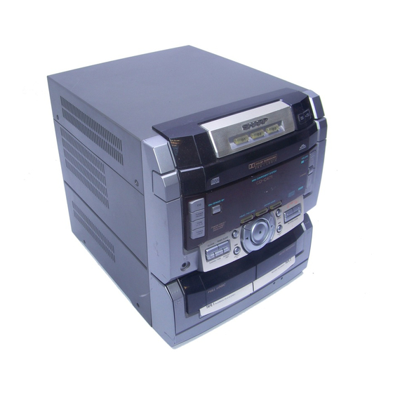
CD-C471 W mini component system consisting of
CD-C471 W mini component system, front (CP-C471), senter
Speaker System.
In the interests of user-safety the set should be restored to its
l
original condition and only parts identical to those specified be
used.
This document has been published to be used
for after sales selvice only.
The contents are subject to change without notice.
2
2
3
4
6
7
11
14
14
15
18
39
40
44
54
Advertisement
Table of Contents

Related Manuals for Sharp CD-C471 W


Summary of Contents for Sharp CD-C471 W
-
Page 1: Table Of Contents
CD-C471 W mini component system consisting of CD-C471 W mini component system, front (CP-C471), senter Speaker System. In the interests of user-safety the set should be restored to its original condition and only parts identical to those specified be used. -
Page 2: Safety Precaution For Service Manual
CD-C471 W Laser Dkode Properties Material: GaAlAs Wavelength. 780 nm Emission Duration: continuous Laser Output: max. 0.6 mW Precaution to be taken when replacing and servicing the Laser Pickup. The AEL (Accessible Emission Level) of Laser Power Output However, the following precautions must be observed during... -
Page 3: Specifications
CD-C471 W FOR A COMPLETE DESCRIPTION OF THE OPERATION OF THIS UNIT, PLEASE REFER TO THE OPERATION MANUAL. AC 11 O/l 27/2201230-240 V, Compact cassette tape Power source: Type: 50160 50 - 14,000 Hz (Normal tape) Frequency response: 112w Power consumption:... -
Page 4: Names Of Parts
Front Panel 2. (CD) Disc Number Select Buttons 3. (CD) Disc Skip Button 4. (CD) Open/Close Button: 4 5. (CD) Play Indicator: ) 6. (CD) Repeat Indicator: 4 7. (CD) Pause Indicator: 11 8. (CD) Disc Number Indicators 9. Dolby Pro Logic Indicator 10. - Page 5 Rear Panel 2. AC Voltage Selector 3. AC Power Input Socket 4. AM Aerial Terminal 5. Aerial Earth Terminal 6. FM 75 Ohms Aerial Terminal 7. Video/Auxiliary (Audio Signal) Input Sockets 8. Sub Woofer Output Socket 9. Span Selector Switch 12.
-
Page 6: Operation Manual
T U N I N G / ’ TIME... -
Page 7: Disassembly
CD-C471 W Caution on Disassembly Follow the below-mentioned notes when disassembling the unit and reassembling it, to keep it safe and ensure excellent performance: 2. Be sure to remove the power supply plug from the wall outlet before starting to disassemble the unit. - Page 8 Front Panel Tuner P W B 03 xlOmm CD Servo P W B Loading Chassis 03 xl Omm Figure 8-5 Figure 8-1 Washer Turntable xl Omm 03 x8mm Figure 8-2 Switch PWB Figure 8-6 xl Omm 02.6 xl Omm Figure 8-3 03 xl 2mm Power Be careful when installing the CD changer mechanism.
- Page 9 CD-C471 W PROCEDURE 1 Net ......(Al) xl 2. Fromt Panel ... (A2) xl 3. Screw ..... (A3) x2 4. Screw ..... (A4) x4 Note: The center and SURROUND speakers can be easily disas- sembled. Therefore the disassembling method is not discribed.
-
Page 10: Removing And Reinstalling The Main Parts
CD-C471 W CD MECHANISM SECTION Perform steps 1, 2, 3, 14 and 15 of the disassembly method to remove the CD mechanism. Turntable Up/Down M How to remove the turntable up/down motor (See Fig. IO-I) up/down motor. Figure 10-l How to remove the pickup (See Fig. 10-2) 1. -
Page 11: Adjustment
CD-C471 W TUNER SECTION MECHANISM SECTION Driving Force Check Torque Meter Specified Value AM IF/RF Tape 1: Over 80 g Play: TW-2412 Signal generator: 400 Hz, 30%, AM modulated Tape 2: Over 80 g Test Stage Frequency Frequency Torque Check... -
Page 12: Test Mode
CD-C471 W TEST MODE Setting the test mode Any one of test mode can be set by pressing several keys as follows. <REC. PAUSE> + <CD> + <POWER> TEST: CD operation test TEST mode Function - CD test mode IL is not performed. - Page 13 CD-C471 W EXPLANATION OF DOLBY SURROUND PRO LOGIC AND EVALUATION METHOD Outline In the normal mode of Pro Logic ON mode the amplifiers for Namely, two speakers are connected in parallel to one amplifier. appears. In the Pro Logic BYPASS mode the amplifierfor C-ch (center...
-
Page 14: Notes On Schematic Diagram
CD-C471 W Resistor: The indicated voltage in each section is the one measured To differentiate the units of resistors, such symbol as K and by Digital Multimeter between such a section and the chas- sis with no signal given. 1. In the tuner section, ohm-type resistor. - Page 15 DIGITAL...
-
Page 16: Block Diagram
Figure 16 BLOCK DIAGRAM (2/3) - Page 17 CD-C471 W Figure 17 BLOCK DIAGRAM (3/3)
-
Page 18: Schematic Diagram /Wiring Side Of P.w.board
CD-C471 W PICKUP UNIT The numbers 0 to @ are waveform numbers shown in page 39. NOTES ON SCHEMATIC DIAGRAM can be found on page 14. Figure 18 SCHEMATIC DIAGRAM (l/13) - Page 19 CD-C471 W Figure 19 SCHEMATIC DIAGRAM (Z/l 3)
- Page 20 CD-C471 W NOTES ON SCHEMATIC DIAGRAM can be found on page 14. Figure 20 SCHEMATIC DIAGRAM (3/13)
- Page 21 MAIN PWB-A1(1/2) HEADPHONE AMP. Figure 21 SCHEMATIC DIAGRAM (4/13)
- Page 22 CD-C471 W NOTES ON SCHEMATIC DIAGRAM can be found on page 14. Figure 22 SCHEMATIC DIAGRAM (5/l 3)
- Page 23 CD-C471 W Figure 23 SCHEMATIC DIAGRAM (6/13)
- Page 24 CD-C471 W FL701 SYSTEM MICROCOMPUTER ; NOTES ON SCHEMATIC DIAGRAM can be found on page 14. Figure 24 SCHEMATIC DIAGRAM (7/l 3)
- Page 25 CD-C471 W INPUT/OUTPUT EXPANDER Figure 25 SCHEMATIC DIAGRAM (8/13)
- Page 26 CD-C471 W STK40704 POWER AMP. NOTES ON SCHEMATIC DIAGRAM can be found on page 14. Figure 26 SCHEMATIC DIAGRAM (9/I 3)
- Page 27 CD-C471 W LA4450 POWER AMP. I- 1 Figure 27 SCHEMATIC DIAGRAM (10113)
- Page 28 CD-C471 W ANTENNA 750hms CHASSIS CHASSIS FE301 FM FRONTEND * NOTES ON SCHEMATIC DIAGRAM can be found on page 14. Figure 28 SCHEMATIC DIAGRAM (1 l/13)
- Page 29 CD-C471 W . ..3.9K MTZJ5.1 f KRC107 M D351 n Figure 29 SCHEMATIC DIAGRAM (12/13)
- Page 30 CD-C471 W Figure 30 SCHEMATIC DIAGRAM (13/l 3)
- Page 31 CD-C471 W DISPLAY PWB-A2 Figure 31 WIRING SIDE OF P.W.BOARD (l/E) - 3 1 -...
- Page 32 CD-C471 W Figure 32 WIRING SIDE OF P.W.BOARD (2/8)
- Page 33 CD-C471 W BLACK PINK Figure 33 WIRING SIDE OF P.W.BOARD (3/8)
- Page 34 TAPE MOTOR The numbers @ to @ are waveform numbers shown in page 39. Figure 34 WIRING SIDE OF P.W.BOARD (4/8)
- Page 35 CD-C471 W Figure 35 WIRING SIDE OF P.W.BOARD (5/8)
- Page 36 Figure 36 WIRING SIDE OF P.W.BOARD (6/8)
- Page 37 CD-C471 W Figure 37 WIRING SIDE OF P.W.BOARD (7/8)
- Page 38 CD-C471 W ANTENNA Figure 38 WIRING SIDE OF P.W.BOARD (8/8)
-
Page 39: Waveforms Of Cd Circuit
CD-C471 W WAVEFORMS OF CD CIRCUIT 5.0 v... -
Page 40: Troubleshooting (Cd Changer Control / Cd Section)
CD-C471 w TROUBLESHOOTING (CD SECTION) When the CD does not function When the CD section does not operate When the objective lens of the optical pickup is dirty,this section may not operate.Clean the objective lens,and check the playback operation.When this section does not operate even after the above step is taken,check the following items. - Page 41 CD-C471 W Is there following voltage input in specific state of IC701 pin 53? pin 53 to the OPEN CLOSE SW. Open state: OV Close state: OV Intermediate state between open state and close state: 5V Check the wiring of the lC2 pins 24 and 25, IC81 pins 1 and 3.
- Page 42 CD-C471 W . ‘. Check the laser diode driver. Is the Focus servo active? (Can you hear it working?) Check the area around ICl(16) b (21) (focus servo circuit). If the disc is not turning, the DRF Check the spin system.
- Page 43 CD-C471 W Play operation is performed without disc. The turntable rotates a little. The spin driver circuit is normal. Check the periphery of ICl pins 23 to 27, pin 39, and pin 40, IC2 The turntable fails to rotat pin 12 and pin 13, IC3 to CNPB.
-
Page 44: Function Table Of Ic
CD-C471 W FUNCTION TABLE OF IC Pin No. / Terminal Name 1 Input/Output 1 Function Input Input terminal of defect detectron signal (DEF). (Connected to OV when not used.) Input For PLL Input terminal for test. Pull-down resistor is integrated. Surely connected to OV. - Page 45 CD-C471 W Note: The same potential must be supplied to the, power terminals (VDD, VVDD, LVDD, RVDD, XVDD). In this unit, the terminal with asterisk mark (*) is (&pen) terminal which is not connected to the outside. RAM address Interpolation mute...
- Page 46 CD-C471 W Function Pin No. Port Name Connection pin for photodiode of pickup. FIN2 RF signal is generated through addition with FIN pin, and FE signal is generated through subtraction. Connection pin for photodiode of pickup. Connection pin for ohotodiode of pickuo. TE sianal is aenerated throuah subtraction with F Din.
- Page 47 CD-C471 W Function Port Name Pin No. Micro computer command clock input pin. Micro computer command data input pin. Micro computer command chip enable input pin. (DETECT RF) RF level detection output. (Focus Serch Select) Pin to switch focus search mode. (rt search/+ search for reference voltage) vcc2 VCC pin for servo system and digital system.
- Page 48 CD-C471 W Pin No. Terminal Name Function output I - - - - CD MUT output CD MUT signal CD RES output CD DSP RESET srgnal output Slide return signal CD SL- CD SL+ output Slide feed signal Power connection terminal...
- Page 49 CD-C471 W TAPE PB EQ output Tape circuit playback Eq selection output Tape circuit record muting output TAPE REC MUT In this unit, the terminal with asterisk mark (*) is (open) terminal which is not connected to the outside.
- Page 50 CD-C471 W Port Name Pin No. Terminal Name Input/Output Function Output FL display tube grid drive Output FL display tube grid drive Positive power supply Output Output Input Output SUB STB Output Serial strobe output for CD/TAPE microcomputer SUB SCK...
- Page 51 CD-C471 W Port Pin No. Name Terminal Name Function VLOAD VLOAD Negative power supply for FL drive To be connected to -30V 72-76 output FL display tube segment drive output FL display tube grid drive output FL display tube grid drive...
- Page 52 CD-C471 W Terminal to connect capacitor of filter configuration for equalizer F5 band Terminal to connect capacitor of filter configuration for equalizer F2 band In this unit, the terminal with asterisk mark (*) is (open) terminal which is not connected to the outside.
-
Page 53: Fl Display
CD-C471 W & i Standby Standby Gain4 Regbase Figure 54-1 BLOCK DIAGRAM OF IC FL701 : VVKBJ549GKb1 FL Display R D S S T 4-SP S L E E P Figure 54-2 FL DISPLAY... - Page 54 CD-C471 W MEMO...
- Page 55 CD-C471 W SHARP PARTS GUIDE M O D E L CD-C471 W mini component system consisting of Speaker System. “HOW TO ORDER REPLACEMENT PARTS” To have your order filled promptly and correctly, please furnish the following information. Contact your nearest SHARP Parts Distributor to order.
- Page 56 PART CODE DESCRIPTION PARTS CODE * TA;; DESCRIPTION RANK A A Silicon,lSS133 A A SiliconlSS133 Servo Amp.,LA9241 M A P Silicon,TSGB04GM-1 AB ; Silicon,RL104A Focus/Tracking/Spin/Slide AA : Silicon,lSS133 AA I Silicon,lSS133 Loading Motor Driver,TA7291S D824 Optical Fiber Data LinkGPl F32T A A Silicon,lSS133 D827 Playback and Record/Playback...
- Page 57 CD-C471 PRICE PRICE PART CODE * DESCRIPTION PARTS CODE * DESCRIPTION RANK RANK AA 0.001 uF,5OV C332 AB 0.47 uF,SOV,Eiectrolytic c334 VCEAZAl HWI 05M J c335 VCEAZAI CW476M 3 AB 47 uF,l GV,Electrolytic C336 470 pF,SOV AA 0.0033 uF,16V c337 AA 220 pF,5OV VCTYMNl CX272K J AA 0.0027 pF,16V...
- Page 58 CD-C471 W PRICE DESCRIPTION PART CODE P A R T S C O D E * RANK DESCRIPTION RANK 10 pF,50V,Electrolytic C536 c537 10 vF,50V,Electrolytic B 47 pF,lGV,Electrolytic VCEAZAl CW227M 220 pF,l GV,Electrolytic c539 VCEAZAl HWIOGM 10 pF,50V,Electrolvtic C726 150 pF,5OV...
- Page 59 CD-C471 W DESCRIPTION PART CODE PARTS CODE DESCRIPTION RANK RANK A 1 kohm,l/6W 1 kohm,li%W R35.36 A 10 kohm,l/EiW 1 kohm,l/6W A 1 kohm,l/8W A 1 kohm,l/6W A I kohm,l/EW A 1 kohm,l/EW 1 kohm,l/8W A 1 kohm,l/6W A 560ohms,ll%W...
- Page 60 CD-C471 W PRICE PART CODE DESCRIPTION DESCRIPTION PARTS CODE RANK RANK 100 ohm,l/8W 1 kohm,l/6W 1 kohm,l/8W 8.2 kohms,1/8W 39 kohms,l/8W AA 8.2 kohms,l/6W 68 kohms, 118W 8.2 kohms,l/8W AA 22 kohms,l/8W 1 kohm,l/6W 470 kohms,llBW 820 ohms,li6W 15 kohms,l/6W...
- Page 61 CD-C471 W PRICE DESCRIPTION PARTS CODE DESCRIPTION PART CODE RANK FE301 FL701 1 kohm,lWW JK452 L Jack,VIDEO/AUX JK700 F Jack,Headphones A 1 kohm,l/6W AP Motor with Worm Gear Pulley AT Motor with Pulley [Tape] 1 kohm,l/8W RX701 H Terminai,Antenna SO801...
- Page 62 CD-C471 W PARTS CODE * y;$. DESCRIPTION DESCRIPTION PART CODE RANK 244-17 B LuaTerminal ILua 11 C Gear,Drive [Not Replacement Item) C RaiLGuide B CushionLea (Not Replacement Item) (Not Replacement Item) (Not Replacement Item) 251-2 251-3 A RingSpring Motor with Chassis [Disc]...
- Page 63 CD-C471 W PARTS CODE DESCRIPTION DESCRIPTION PART CODE RANK RANK Polyethylene Bag,Accessories Polyethylene Bag,AC Plug [For Hong Kong] [For Saudi Arabia] V NetFrameAss’ y.,Right AC Power Supply Cord [Except for Saudi Arabia] AC Power Supply Cord C HolderCatcher [For Saudi Arabia] N SuperTweeterAss’...
- Page 64 CD MECHANISM EXPLODED VIEW...
- Page 65 CD-C471 W 244 --/ 244-5 254-5.254-6, 254-7) TAPE MECHANISM 616x2 CABINET EXPLODED VIEW (l/2)
- Page 66 CD-C471 W 609x2 CABINET EXPLODED VIEW (2/2)
- Page 67 CD-C471 W SUPER TWEETER SP5 (L-CH) rn E----l SPEAKER EXPLODED VIEW (l/2)
- Page 68 CD-C471 W CD-C471 W WOOFER WOOFER SPEAKER EXPLODED VIEW (2/2) SPEAKER EXPLODED VIEW...
- Page 69 CD-C471 W WOOFER SP2 (R-CH) SPEAKER EXPLODED VIEW (2/2)
- Page 71 CD-C471 W MEMO...
- Page 72 CD-C471 W COPYRIGHT @ 1998 BY SHARP CORPORATION ALL RIGHTS RESERVED. No pat-t of this publication may be reproduced, stored in a retrieval system, or transmitted in any form or by any means, electronic, mechanical, photocopying, recording, or otherwise, without prior written permission of the publisher.