Table of Contents
Advertisement
Quick Links
SERVICE MANUAL
Ver 1.0 1999. 03
Manufactured under license from Dolby Laboratories
Licensing Corporation.
"DOLBY" and the double-D symbol a are trademarks
of Dolby Laboratories Licensing Corporation.
Radio section
Frequency range
FM : 87.5 – 108 MHz
AM : 531 – 1,602 kHz
Tape section
Frequency response
(Dolby NR off)
Playback : 20 – 18,000 Hz
Output
Headphones (2 REMOTE jack)
Load impedance 8 – 300 Ω
General
Power requirements
1.5 V
One R6 (size AA) battery
Rechargeable battery
MICROFILM
WM-FX571
Model Name Using Similar Mechanism
Tape Transport Mechanism Type
SPECIFICATIONS
Dimensions (w/h/d)
Approx. 109 × 79.2 × 29.4 mm
× 3
× 1
(4
3/8
1/8
projecting parts and controls
Mass
Approx. 150 g (5.3 oz)
Approx. 210 g (7.5 oz) incl.
a battery and a cassette
Supplied accessories
Stereo earphones with remote
control MDR-WMF653 (1)
Battery charger BC-820T (1)
AC plug adaptor (1)
Rechargeable battery (NC-AA) (1)
Battery R6P (SR) (1)
Carrying pouch (1)
Design and specifications are subject to
charge without notice.
RADIO CASSETTE PLAYER
– 1 –
Tourist Model
WM-FX551/FX553
MF-WMFX551-125
inches) incl.
3/16
Advertisement
Table of Contents

Related Manuals for Sony Walkman WM-FX571


Summary of Contents for Sony Walkman WM-FX571
- Page 1 WM-FX571 SERVICE MANUAL Tourist Model Ver 1.0 1999. 03 Manufactured under license from Dolby Laboratories Model Name Using Similar Mechanism WM-FX551/FX553 Licensing Corporation. Tape Transport Mechanism Type MF-WMFX551-125 “DOLBY” and the double-D symbol a are trademarks of Dolby Laboratories Licensing Corporation.
-
Page 2: Table Of Contents
TABLE OF CONTENTS 1. GENERAL ..............2. SERVICE NOTE ............3. DISASSEMBLY 3-1. Case Assy ................4 3-2. Tuner Board ................ 4 3-3. Audio Board ................ 5 3-4. Cassette Lid Assy ..............5 3-5. Tape Mechanism Deck ............6 4. MECHANICAL ADJUSTMENTS ......5. -
Page 3: General
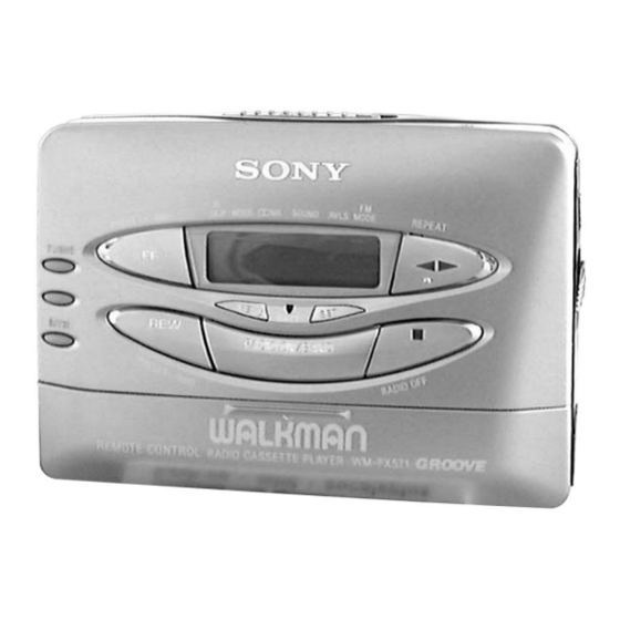
SECTION 1 GENERAL • LOCATION OF CONTROLS 1 OPEN knob 2 Display window 3 PRESET + /AMS FF (Fast Forward) button 4 TUNING + button 5 TUNING – button 6 ENTER button 7 PRESET – /AMS REW (Rewind) button 8 MENU button !™... -
Page 4: Disassembly
SECTION 3 DISASSEMBLY Note : Disassemble the unit in the order as shown below. CASE ASSY TAPE MECHANISM DECK AUDIO BOARD TUNER BOARD CASSETTE LID ASSY Note : Follow the disassembly procedure in the numerical order given. 3-1. CASE ASSY 3 screws (M1.4 ×... -
Page 5: Audio Board
3-3. AUDIO BOARD 2 battery terminal (–) 7 AUDIO board 1 Unsolder the 3 places. 4 battery terminal (+) 3 Unsolder the 5 places. 5 Flexible board 3-4. CASSETTE LID ASSY 2 screw (M1.4 × 2) 5 cassette lid assy 3 screw (M1.4 ×... -
Page 6: Tape Mechanism Deck
3-5. TAPE MECHANISM DECK 4 reel ornament 5 tape mechanism deck – 6 –... -
Page 7: Mechanical Adjustments
SECTION 4 SECTION 5 MECHANICAL ADJUSTMENTS ELECTRICAL ADJUSTMENTS PRECAUTION PRECAUTION Clean the following parts with a denatured-alcahol-moistened Specified voltage : 1.3V sweb : Switch position MENU button : a NR light off (OFF) Playback head Pinch roller Rubber belt Capstan : AVLS light off (OFF) Demagnetize the playback head using a demagnetizer. -
Page 8: Tuner Section
FM VCO Adjustment TUNER SECTION 0 dB=1 µV Procedure : [AM] FM RF signal RADIO ON/BAND button : AM generator AM RF signal 0.01 µ F generator Put the lead-wire antenna to ANT (TP1) close to the set. Carrier frequency : 98MHz Modulation : No moduration Output level :... -
Page 9: Diagrams
WM-FX571 SECTION 6 DIAGRAMS 6-1. BLOCK DIAGRAM 6-2. IC PIN DESCRIPTION • IC1 TC9326F-051 (SYSTEM CONTROL) Pin No. Function Pin Name Circuit Description Remarks Pin No. Function Pin Name Circuit Description Remarks 1 to 3 COM 1 to 3 COM 1 to 3 —... - Page 10 WM-FX571 6-3. PRINTED WIRING BOARD — TUNER SECTION — – 13 – – 14 – – 15 – – 16 –...
- Page 11 WM-FX571 6-4. SCHEMATIC DIAGRAM — TUNER SECTION — • Refer to page 27 for IC Block Diagrams. • Semiconductor Location Ref. No. Location B-20 B-19 A-21 D-19 D-17 E-13 E-13 E-14 E-16 B-13 B-18 B-19 E-13 B-12 G-12 F-20 A-19...
-
Page 12: Schematic Diagram -Audio Section
WM-FX571 6-5. SCHEMATIC DIAGRAM — AUDIO SECTION — • Refer to page 28 for IC Block Diagrams. Note: • All capacitors are in µF unless otherwise noted. pF: µµF 50 WV or less are not indicated except for electrolytics and tantalums. - Page 13 WM-FX571 6-6. PRINTED WIRING BOARD — AUDIO SECTION — • Semiconductor Location Ref. No. Location D701 F-14 D702 C-19 D703 E-13 D704 F-13 D705 G-13 IC301 IC601 IC701 C-19 PH701 E-18 Q301 C-18 Q302 B-13 Q303 Q304 Q306 C-12 Q601...
-
Page 18: Tape Mechanism Section
7-3. TAPE MECHANISM SECTION (MF-WMFX551-125) PM901 M901 HP301 not supplied Ref. No. Part No. Description Remark Ref. No. Part No. Description Remark 3-011-277-01 COVER (B) (Y), MD X-3374-094-1 CHASSIS (S) ASSY (F) 3-704-413-31 SCREW (M1.4X7.2) 3-019-710-01 SPRING (R), TORSION X-3372-850-1 PINCH LEVER (N) ASSY 3-007-458-01 SPRING (H/B), TENSION 3-007-434-01 PULLEY (REVERSE) 3-019-709-01 SPRING (N), TORSION... -
Page 19: Electrical Parts List
SECTION 8 AUDIO ELECTRICAL PARTS LIST NOTE: • Due to standardization, replacements in • Items marked “*” are not stocked since The components identified by the parts list may be different from the they are seldom required for routine service. mark ! or dotted line with mark. - Page 20 AUDIO Ref. No. Part No. Description Remark Ref. No. Part No. Description Remark FB706 1-414-235-22 INDUCTOR, FERRITE BEAD R201 1-216-812-11 METAL CHIP 1/16W FB707 1-414-235-22 INDUCTOR, FERRITE BEAD R202 1-216-847-11 METAL CHIP 150K 1/16W R203 1-216-831-11 METAL CHIP 6.8K 1/16W <...
- Page 21 AUDIO TUNER Ref. No. Part No. Description Remark Ref. No. Part No. Description Remark < SWITCH > 1-164-227-11 CERAMIC CHIP 0.022uF 1-135-151-21 TANTALUM CHIP 4.7uF S701 1-572-922-11 SWITCH, SLIDE (HOLD) 1-115-156-11 CERAMIC CHIP S702 1-572-581-11 SWITCH, SLIDE (F/R) 1-165-176-11 CERAMIC CHIP 0.047uF S703 1-762-970-21 SWITCH, PUSH (1 KEY) (HOLDER)
- Page 22 TUNER Ref. No. Part No. Description Remark Ref. No. Part No. Description Remark < TRIMMER > 8-729-420-68 TRANSISTOR 2SD1328-R-TX 8-729-800-37 TRANSISTOR 2SD1048-X7 1-141-327-11 CAP, CHIP TYPE TRIMMER 10PF 8-729-028-69 TRANSISTOR 2SC4655-BC(TX) 8-729-037-71 TRANSISTOR UN9210J-(TX).SO < DIODE > 8-729-037-63 TRANSISTOR UN9115J-(TX).SO 8-719-053-30 DIODE MA2S357-(TX).SO 8-729-028-69 TRANSISTOR 2SC4655-BC(TX) 8-719-053-30 DIODE MA2S357-(TX).SO...
- Page 23 WM-FX571 TUNER Ref. No. Part No. Description Remark Ref. No. Part No. Description Remark 1-216-833-11 RES,CHIP 1/16W < COIL > 1-216-819-11 METAL CHIP 1/16W 1-216-825-11 METAL CHIP 2.2K 1/16W 1-416-182-11 COIL (AM OSC) 1-216-799-11 METAL CHIP 1/16W 1-416-183-11 COIL (AM MIX)