Table of Contents
Advertisement
Quick Links
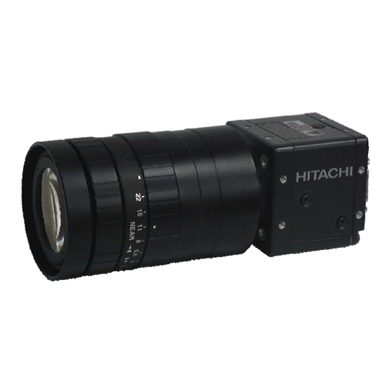
High pixel CMOS camera
KP-FM200WCL
KP-FMR200WCL
Operation Manual
Thank you for purchase this fine Hitachi Kokusai Electric CMOS camera.
Before using the camera, please read this operation manual carefully.
Hitachi Kokusai Electric Inc.
RoHS Compliant
These products comply with the requirement of the RoHS (Restriction of the
use of Certain Hazardous Substances in Electrical and electronic Equipment)
Directive 2002/95/EC.
The third edition in August, 2012.
Advertisement
Table of Contents

Related Manuals for Hitachi KP-FM200WCL


Summary of Contents for Hitachi KP-FM200WCL
- Page 1 High pixel CMOS camera KP-FM200WCL KP-FMR200WCL Operation Manual Thank you for purchase this fine Hitachi Kokusai Electric CMOS camera. Before using the camera, please read this operation manual carefully. Hitachi Kokusai Electric Inc. RoHS Compliant These products comply with the requirement of the RoHS (Restriction of the use of Certain Hazardous Substances in Electrical and electronic Equipment) Directive 2002/95/EC.
-
Page 2: Important Safety Instructions
IMPORTANT SAFETY INSTRUCTIONS 1. Read Instructions All the safety and operating instructions should be read before the product is operated. 2. Retain Instructions The safety and operating instructions should be retained for future reference. 3. Heed Warnings All warnings on the product and the operating instructions should be adhered to. 4. - Page 3 WICHTIGE SICHERHEITSANWEISUNGEN 1. Alle Anweisungen lesen Vor Betrieb des Erzeugnisses sollten alle Sicherheits-und Bedienungsanleitungen gelesen werden. 2. Die Anweisungen aufbewahren Die Sicherheits-und Bedienungsanleitungen sollten fünftigen Bezug aufbewahrt werden. 3. Warnungen beachten Die Warnungen auf dem Erzeugnis und in den Bedienungsanleitungen solten beachtet werden. 4.
- Page 4 MISES EN GARDE IMPORTANTES 1. Lire les instructions Lire toutes les instructions de sécurité et de fonctionnement avant de faire fonctionner l’appareil. 2. Conserver ces instructions Conserver les instructions de sécurité et de fonctionnement á des fins de référence ultérieure. 3.
-
Page 5: Important Notice
Operation of this product in a residential area is likely to cause harmful interference in which case the user will be required to correct the interference at his own expense. WARNING Changes or modifications not expressly approved by Hitachi Denshi responsible for compliance could void the user’s authority to operate the equipment. For Canada This product does not exceed the class A/class B limits for radio noise emissions from digital apparatus as set out in the radio interference regulations. - Page 7 ・ Stop using the camera at the approach of electrical storm (thunder audible). Protect the camera from rain if using it outdoors. ・ In event the camera shows any abnormality, switch off the camera and disconnect the power cord. Contract a Hitachi Denshi service representative.
-
Page 8: Table Of Contents
Table of Contents 1. Overview ··········································································································································· 1 2. Standard Composition ······················································································································· 1 3. Features ············································································································································ 1 4. System example ································································································································ 2 5. Section name and functions ·············································································································· 2 6. Camera mounting ······························································································································ 3 7. Lens ·················································································································································· 3 8. Optical filter ······································································································································· 3 9. -
Page 9: Overview
Overview KP-FM200WCL are Camera Link output type black and white camera which utilized the 2/3 –inch progressive scan CMOS image sensor with square pixel. KP-FMR200WCL are RAW data output type. The high resolution image of two million pixels is output in no interlace by 280 frames per second. -
Page 10: System Example
System example KP-FM200WCL and KP-FMR200WCL connect to frame grabber board using Camera Link cable. HITACHI Power over type Mini-Camera Link cable Power over type Camera Link (x2 when Medium/Full configuration) frame grabber board HITACHI Mini-Camera Link cable (x 2 when Medium/Full configuration) -
Page 11: Camera Mounting
Camera mounting Attached optional accessory the tripod adaptor "TA-FM200", mount the camera to a tripod or mounting bracket. Screw type: U1/4-20 Length L = 4 to 5.5mm Screws longer than 5.5 mm can cause internal damage, while less than 4 mm prevents secure fastening and risks dropping to cause damage and injury. -
Page 12: Connector
Connector 1. Camera Link connector D.OUT1 (Connector 1) Pin No. Signal Pin No. Signal +12V (PoCL) GND (non-PoCL) TXOUT 0 (-) TXOUT 0 (+) TXOUT 1 (-) TXOUT 1 (+) TXOUT 2 (-) TXOUT 2 (+) TXCLKOUT (-) TXCLKOUT (+) TXOUT 3 (-) TXOUT 3 (+) RX (+) [ SERTC (+) ]... -
Page 13: Functions And Operations
Functions and operations Various mode setup and adjustment of KP-FM200WCL and KP-FMR200WCL are performed by the remote control via Camera Link. Operation and adjustment way of function utilized are described below. See "Remote control" and "Command list" (page 7 to 16) about communication method of each command. - Page 14 (4) DATA BIT : Setting of output bit depth 8bit (Factory setting) : Image is outputted by 8 bit. 10bit : Image is outputted by 10 bit. (5) CONFIG : Setting of Camera Link configuration BASE(Factory setting) : Camera Link configuration is set to Base configuration. MEDIUM : Camera Link configuration is set to Medium configuration.
-
Page 15: Remote Control
Remote control 1. Comms* specifications ・Control system : Start-stop synchronization system ・Transmission rate : 9600 bps ・Data length : 8 bit ・Star bit : 1 bit ・Stop bit : 1 bit ・Parity : None ・Bit transfer : LSB first *Comms: Communications 2. - Page 16 HITACHI ACK code (06H) Transmit data (ASCII code) Slave ACK code (06H) (KP-FM200WCL KP-FMR200WCL) Master (Machine) ① Session starts when ENQ is sent from master to slave. ② Slave acknowledges by returning ACK to master. ③ Master sends data to slave.
- Page 17 ENQ code (05H) HITACHI NACK code (15H) ENQ code (05H) NACK code (15H) Slave (KP-FM200WCL ENQ code (05H) KP-FMR200WCL) Master (Machine) NACK code (15H) ① Master sends ENQ code to slave. ② Since ACK code cannot be sent, slave sent NACK code to master.
- Page 18 ACK code (06H) Send data (ASCII code) HITACHI 3 second elapse Send data (ASCII code) Slave 3 second (KP-FM200WCL elapse Send data (ASCII code) KP-FMR200WCL) Master (Machine) 3 second elapse Send data (ASCII code) ① Session starts when ENQ is sent from master to slave.
- Page 19 (6) Transmission frame error (Master receive) ENQ code (05H) ACK code (06H) Read command (ASCII code) HITACHI ACK code (06H) Read data (ASCII code) Slave (KP-FM200WCL 3 second elapse KP-FMR200WCL) Read data (ASCII code) Master (Machine) 3 second elapse Read data (ASCII code)
- Page 20 2 byte (ASCII code) Used for EEPROM write (0: write absent, 1: write present). ・ID No. : Camera peculiar ID. KP-FM200WCL and KP-FMR200WCL have (FFH). 2 byte (ASCII code) ・Area address : Classification of Send data (01H) and Read command (81H).
- Page 21 (2) Read (receive) data (slave to master) (a) Command data are converted into ASCII code and transmitted. (b) Comms byte quantity is 10. (c) Comms data format (transmission sequence) S T X Text data E T X S U M 1 byte 6 byte 1 byte...
-
Page 22: Command List
Command list 1. Send data (Setting command. Note: 1 to 7 and SUM need to be transformed into ASCII code) Item AREA RELATIVE STATUS ID NO. DATA ADDRESS 00 00 00 FIXED 01 00 00 MODE 1TRIG 02 00 00 BURST 03 00 00 POSITIVE... - Page 23 Item AREA RELATIVE STATUS ID NO. DATA ADDRESS 00 00 00 AREA 1AREA 01 00 00 8AREA 08 00 00 AREA1 START 00 01 00 (2Byte) 1088 04 40 00 AREA1 WIDTH 00 01 00 (2Byte) 1088 04 40 00 AREA2 START 00 01 00 (2Byte)
- Page 24 2. Read command (Note: 1 to 7 and SUM need to be transformed into ASCII code) Item ETX SUM AREA RELATIVE STATUS ID NO. DATA ADDRESS MODE POLARITY TRIGGER SOURCE BURST NUM PRESET SHUTTER VARIABLE VALUE SPEED MULTI SHUT NUM INC EXP STEP OUTPUT SIGNAL CONFIG...
-
Page 25: Camera Link Output Timing Chart
Camera Link output timing chart 1. Horizontal timing (1) 80MHz Base configuration (1 clk = 12.5 ns) 8 clk 1024 clk LVAL ・ ・ ・ ・ ・ ・ ・ ・ VIDEO Active Picture ・ ・ ・ ・ ・ ・ ・ ・ (2) 40MHz Base configuration (1 clk = 25 ns)... - Page 26 (5) 80MHz Full configuration (1 clk = 12.5 ns) 256 clk 2 clk LVAL ・ ・ ・ ・ ・ ・ ・ ・ ・ ・ ・ ・ ・ ・ ・ ・ ・ ・ ・ ・ ・ ・ ・ ・ ・ ・ ・ ・ ・...
- Page 27 2. Vertical timing 1088 H (Set value of width at partial scanning ON.) FVAL VIDEO Active Picture One horizontal period and branking period (*1) are different because of the setting of the configuration and the clock frequency. Cameralink output setting One horizontal period Branking period (*1) Base configuration 40MHz...
- Page 28 3. Transmitter LVDS output pulse position measurement (1)Base configuration (a)8bit D.OUT1 12.5ns (80MHz) or 25ns (40MHz) TXCLKOUT Previous Cycle Next Cycle TXOUT 3 DA7-1 DA6-1 N.U. N.U. N.U. TXOUT 2 N.U. N.U. N.U. FVAL LVAL N.U. N.U. N.U. N.U. TXOUT 1 DB2-1 DB1-1 N.U.
- Page 29 (2)Medium configuration (a)8bit D.OUT1 12.5ns (80MHz) or 25ns (40MHz) TXCLKOUT Previous Cycle Next Cycle TXOUT 3 DA7-1 DA6-1 N.U. TXOUT 2 DC3-1 DC2-1 N.U. FVAL LVAL TXOUT 1 DB2-1 DB1-1 TXOUT 0 DA1-1 DA0-1 N.U.: Not used D.OUT2 12.5ns (80MHz) or 25ns (40MHz) TYCLKOUT Previous Cycle Next Cycle...
- Page 30 (b)10bit D.OUT1 12.5ns (80MHz) or 25ns (40MHz) TXCLKOUT Previous Cycle Next Cycle TXOUT 3 DA7-1 DA6-1 N.U. N.U. N.U. TXOUT 2 DB3-1 DB2-1 N.U. FVAL LVAL TXOUT 1 DA9-1 N.U. N.U. TXOUT 0 DA1-1 DA0-1 N.U.: Not used D.OUT2 12.5ns (80MHz) or 25ns (40MHz) TYCLKOUT Previous Cycle Next Cycle...
- Page 31 (3)Full configuration (a)8bit D.OUT1 12.5ns (80MHz) or 25ns (40MHz) TXCLKOUT Previous Cycle Next Cycle TXOUT 3 DA7-1 DA6-1 N.U. TXOUT 2 DC3-1 DC2-1 N.U. FVAL LVAL TXOUT 1 DB2-1 DB1-1 TXOUT 0 DA1-1 DA0-1 N.U.: Not used D.OUT2 12.5ns (80MHz) or 25ns (40MHz) TYCLKOUT Previous Cycle Next Cycle...
- Page 32 4. Output sequence DA, DB, DC, DD, DE, DF, DG and DH show output TAP of the cameralink. Refer to “Transmitter LVDS output pulse position measurement“ for details. (1) Base configuration 2048 pixels 1024 pixels 1088 lines (2) Medium configuration 2048 pixels 512 pixels 1088...
- Page 33 (3) Full configuration 2048 pixels 256 pixels 1088 lines 5. Color Output sequence(KP-FMR200WCL) 2048 pixels ・ ・ ・ ・ ・ ・ ・ ・ ・ ・ ・ ・ ・ ・ G B R G ・ ・ ・ ・ ・ ・ ・ ・ ・ ・ ・ ・ ・ ・ ・...
-
Page 34: Trigger Operation And Timing Chart
Trigger operation and timing chart 1. Normal mode The exposure and the image output are repeated at the set shutter speed. When the multi shutter speed is set, exposure time (Shutter time) increases every one frame, and one cycle's worth of an image is output repeatedly. Shutter time (Camera setting value) Shutter time... - Page 35 Frame rate can be calculated from following equations using width of picture grabbing. Cameralink output setting Total lines Frame rate(fps) Base configuration 40MHz (Width+3.25)H 40000000/(Width+3.25)/1032 Base configuration 80MHz (Width+4.5)H 40000000/(Width+4.5)/516 Medium configuration 40MHz (Width+4.5)H 40000000/(Width+4.5)/516 Medium configuration 80MHz (Width+7)H 40000000/(Width+7)/258 Full configuration 40MHz (Width+7)H 40000000/(Width+7)/258...
- Page 36 2. Fixed shutter mode When trigger polarity setting is , after the trigger signal rise, exposure is start. The exposure time is set by POSITIVE the camera electronic shutter speed. The video output is obtained immediately after the end of fixed exposure. (*1) More than 10μs High...
- Page 37 3. ONE trigger mode When trigger polarity setting is , after the trigger signal rise, exposure is start. At the trigger signal falling POSITIVE edge, the internal VD signal is reset and the video data are transmitted. The trigger signal width equals the exposure time.
- Page 38 4. Burst trigger mode When trigger polarity setting is , after the trigger signal rise, exposure is start. The exposure time is set by POSITIVE the camera electronic shutter speed. The video output is obtained immediately after the end of fixed exposure. Thereafter, images of the set number of burst-frame are continuously output.
-
Page 39: Input / Output Signal
(2) Input from DCIN/SYNC connector High level : +2.5 to +5.0 V Low level 0 to +0.3 V 2. Output signal The level of the VD and FLASH output from KP-FM200WCL and KP-FMR200WCL is as follows. High level : +5.0V Low level : 0V... -
Page 40: Spectral Response
Spectral response Spectral response of KP-FM200WCL and KP-FMR200WCL are showing. 1. KP-FM200WCL 1000 1100 Wave length(nm) 2. KP-FMR200WCL IR cut filter 1000 1100 Wave length(nm) -
Page 41: Specifications
Specifications Specifications of KP-FM200WCL and KP-FMR200WCL are showing. KP-FM200WCL KP-FMR200WCL Imaging device 2/3-inch global shutter method CMOS Effective pixels 2048 (H) x 1088 (V) Pixel size 5.5μm (H) x 5.5μm (V) Color filter None RGB primary color mosaic filter Image area 11.264mm (H) x 5.984mm (V) -
Page 42: Dimensions
Dimensions ・MASS : APPROX 130g ・UNIT : mm ・SCALE : NTS 4×M3(DEPTH:3) ±0.5 ±1 10.5 33.5 ±0.5 ±1.5 44 47 4×M3(DEPTH:5.5) ±0.5 ±0.5 ±1 0.5 28 40.5 6 ±0.5 ±0.5 ±1 22 10.5 33.5 PLATE,RATED SER.NO. D.OUT 1 D.OUT 2 DC IN/ SYNC 2×4×M3(DEPTH:3) COLOR:BLACK... - Page 43 UDX Akihabara Bldg. 14-1 Sotokanda 4-choume, Chiyoda-ku, Tokyo 101-8980, Japan Phone: +81(0) 3-6734-9432, Fax: +81(0) 3-5209-5942 URL: http://www.hitachi-kokusai.co.jp Hitachi Kokusai Electric (Shanghai) Co., Ltd. Beijing Branch : Room 1413, Beijing Fortune Building, 5 Dong San Huan Bei-Lu, Chao Yang District, Beijing, 100004 China Phone: +86(0) 10-6590-8755/8756, Fax: +86(0) 10-6590-8757 Hitachi Kokusai Electric America, Ltd.