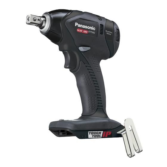
Panasonic EY75A2 Service Manual
Cordless impact driver
Hide thumbs
Also See for EY75A2:
- Operating instructions manual (136 pages) ,
- Owner's manual (57 pages) ,
- Operating instructions manual (14 pages)
Advertisement
Quick Links
TABLE OF CONTENTS
1 Warning -------------------------------------------------------------- 2
2 Specifications ----------------------------------------------------- 2
3 Troubleshooting Guide ----------------------------------------- 3
4 Disassembly and Assembly Instructions ---------------- 7
5 Wiring Connection Diagram ---------------------------------12
6 Schematic Diagram ---------------------------------------------12
7 Exploded View and Replacement Parts List -----------13
Model No.
Europe
Oceania
PAGE
© Panasonic Eco Solutions Power Tools Co., Ltd.
2012. All rights reserved. Unauthorized copying and
distribution is a violation of law.
Order Number PTD1211X11CE
Cordless Impact Driver
EY75A2
PAGE
Advertisement

Related Manuals for Panasonic EY75A2


Summary of Contents for Panasonic EY75A2
-
Page 1: Table Of Contents
4 Disassembly and Assembly Instructions ---------------- 7 5 Wiring Connection Diagram ---------------------------------12 6 Schematic Diagram ---------------------------------------------12 7 Exploded View and Replacement Parts List -----------13 © Panasonic Eco Solutions Power Tools Co., Ltd. 2012. All rights reserved. Unauthorized copying and distribution is a violation of law. -
Page 2: Warning
1 Warning Caution: • Pb free solder has a higher melting point that standard solder; Typically the melting point is 50 - 70°F (30 - 40°C) higher. Please use a soldering iron with temperature control and adjust it to 750 ± 20°F (400 ± 10°C). In case of using high temperature solder- ing iron, please be careful not to heat too long. -
Page 3: Troubleshooting Guide
3 Troubleshooting Guide 3.1. Troubleshooting Guide (Refer to Wiring Connection Diagram) - Page 6 3.2. Trial Operation (after checking Troubleshooting Guide) 3.2.1. Assembly • Confirm if there is no gap between housing A and B by pinching lead wires. • There is no dust or deformation on battery terminals. • Confirm if there is no dirt when repairing. 3.2.2.
-
Page 7: Disassembly And Assembly Instructions
4 Disassembly and Assembly Instructions *To assemble the tool, start with 4-6 and proceed to 4-1 4.1. Removing the Housing 4.2. Removing the Assemblies... - Page 8 4.3. Removing the Motor Mounting Plate, Driving Shaft Assembly, and Fixa- tion Cover Assembly from the Motor Assembly 4.4. Removing the Fixation assembly, Driving shaft assembly, and Motor Mounting Plate...
- Page 9 4.5. Removing the Motor Assembly, Switch Assembly, and Module assembly...
- Page 10 4.6. Precautions When Assembling the Motor Assembly, Switch Assembly, and Module Assembly...
- Page 11 4.7. Wiring and Assembly Points...
-
Page 12: Wiring Connection Diagram
5 Wiring Connection Diagram 6 Schematic Diagram... -
Page 13: Exploded View And Replacement Parts List
7 Exploded View and Replacement Parts List Model No. : EY75A2 Exploded View... - Page 14 Model No. : EY75A2 Parts List Ref. Safety Part No. Part Name & Description Q'ty Remarks WEY75A2H3079 HOUSING AB SET 1 (for EUROPE) WEY75A2H3070 HOUSING AB SET 1 (for OCEANIA) WEY75A2K4058 FIXATION COVER ASSEMBLY WEY75A2L1067 DRIVING SHAFT ASSEMBLY WEY7546L0027 MOTOR MOUNTING PLATE ASSEMBLY...