Toshiba Strata CIX40 Installation And Maintenance Manual
R4.12 software
Hide thumbs
Also See for Strata CIX40:
- General description manual (206 pages) ,
- User manual (96 pages) ,
- Quick start manual (2 pages)

Related Manuals for Toshiba Strata CIX40


Summary of Contents for Toshiba Strata CIX40
- Page 1 TOSHIBA Telecommunication Systems Division ™ Strata CIX40 R4.12 Software Installation and Maintenance Manual Cover July 2006...
-
Page 2: Radio Frequency Interference
2. FCC registration number: equipment must also be installed using an acceptable method of connection. • Strata CIX40 may be configured as a Key, Hybrid or PBX telephone The customer should be aware that compliance with the above conditions may system. - Page 3 License Agreemant TOSHIBA AMERICA INFORMATION SYSTEMS, INC. (“TAIS”) Telecommunication Systems Division License Agreement IMPORTANT: THIS LICENSE AGREEMENT (“AGREEMENT”) IS A LEGAL AGREEMENT BETWEEN YOU (“YOU”) AND TAIS. CAREFULLY READ THIS LICENSE AGREEMENT. USE OF ANY SOFTWARE OR ANY RELATED INFORMATION (COLLECTIVELY, “SOFTWARE”) INSTALLED ON OR SHIPPED WITH A TAIS DIGITAL SOLUTIONS PRODUCT OR OTHERWISE MADE AVAILABLE TO YOU BY TAIS IN WHATEVER FORM OR MEDIA, WILL CONSTITUTE YOUR ACCEPTANCE OF THESE TERMS, UNLESS SEPARATE TERMS ARE PROVIDED BY THE SOFTWARE SUPPLIER.
- Page 4 The sole obligation of TAIS or Toshiba Corporation under this warranty, or under any other legal obligation with respect to the equipment, is the repair or replacement of such defective or missing parts as are causing the malfunc- tion by TAIS or its authorized dealer with new or refurbished parts (at their option).
-
Page 5: Table Of Contents
IP Default Data for GIPH1 Card ....................1-43 Call Monitor ............................1-44 Chapter 2 – CIX40 IP Telephony Install the GIPH1 ..........................2-2 GIPH1 Installation ........................2-2 Connect GIPH1 to LAN or VPN Server ..................2-2 Install IP Telephones ..........................2-3 Strata CIX40 Installation & Maintenance 7/06... - Page 6 This page is intentionally left blank.
-
Page 7: Chapter 1 - Cix40 Installation
Boards. CIX40 programming requires eManager 4.12-A05 or later. GVPH programming requires UADM2 or later. CIX40 Introduction The Strata CIX40 system is designed for wall mounting and occupies very little space. It is a compact system that provides large system features. Refer to Table 1-1 for cabinet dimensions and weight. -
Page 8: Cix40 System Capacities
Safety Registration UL60950-1 (USA) • CSA22.2 NO.60950-1-3 (Canada) • CIX40 FCC/ACTA Registration Numbers • ACTA/FCC Part 68 Registration for Key System Code (KD): CJ6KD03BDTCHS40 ACTA/FCC Part 68 Registration for Multifunction Code (MF): CJ6MF03BDTCHS40 • Strata CIX40 Installation & Maintenance 5/06... -
Page 9: Cix40 System Licenses
• SoftIPT. Telephone Compatibility The Strata CIX40 supports all current Toshiba 2000-series, 3000-series and 3200-series digital telephones, IP telephones, Add-on Modules, DSS Consoles, and CIX Attendant Consoles. Generic single-line telephones (2500-sets) are compatible. The Strata CIX40 does not support analog electronic telephones (6500-series, 6000-series, etc.). -
Page 10: Telephone Compatibility
CIX40 Installation Telephone Compatibility SD Memory Card Slot Modem Paging GCTU2 Relay Contact CO Trunk Connectors Stations and PFT GMAU2 Figure 1-2 Basic CIX40 Interior Strata CIX40 Installation & Maintenance 5/06... -
Page 11: Cix40 Cabinet Slots
16 Busy Tone (BT) detector circuits for Auto Busy Redial (ABR). • 64 built-in conference circuits. CIX40 Cabinet Card Locations BSIS GSTU1 GCTU2 GCDU2 GMAU2 GVPH1 GIPH1 Figure 1-4 CIX40 (Side view) Card Locations Strata CIX40 Installation & Maintenance 5/06... -
Page 12: Gctu2 Processor Interfaces
External Page Interface A 600 ohm RCA jack is built into the processor to interface with a Toshiba External Amplified Speaker (HESB or BESCB) or a customer-supplied page amplifier and speaker(s) for external paging, night ring over external page, and external BGM applications. -
Page 13: Inspection
When packaging and storing the system, remove PCBs from the system cabinet. PCBs should be packaged in their original antistatic bags for protection against electrostatic discharge. Be sure to package equipment in its original shipping containers. Strata CIX40 Installation & Maintenance 5/06... -
Page 14: Site Requirements
To avoid accidental power turn-off, Toshiba recommends that you do not use an On/Off wall switch on this dedicated AC circuit. For the Strata CIX40, a reserve power source (HPFB-6) may be connected to the system to serve as a power failure backup (See Step 9 on page 1-29). - Page 15 -24VDC (-26.3 ~ -28.3VDC) DC voltage output specification +5VDC (+4.5 ~ +5.5VDC) Standard Telephone Ring Circuit (GMAU2 and GSTU1) Ring Voltage 180V p-p square wave Ringing capability 1 REN, 1 circuit - one telephone per circuit Strata CIX40 Installation & Maintenance 5/06...
-
Page 16: Ac Power And Grounding Requirements
GVPH1 greetings and messages. In extreme cases, system failure may result because the system is not properly protected from lightning or power transients. 1-10 Strata CIX40 Installation & Maintenance 5/06... -
Page 17: Ground Wire Connection
Table 1-3 Ground Wiring Summary Grounding Requirement From Description System connects to earth ground Earth ground TB3 on GMAU2 Less than 1 ohm FG of HPFB-6 connect to GMAU2 HPFB-6 FG Screw TB1 on GMAU2 1-11 Strata CIX40 Installation & Maintenance 5/06... -
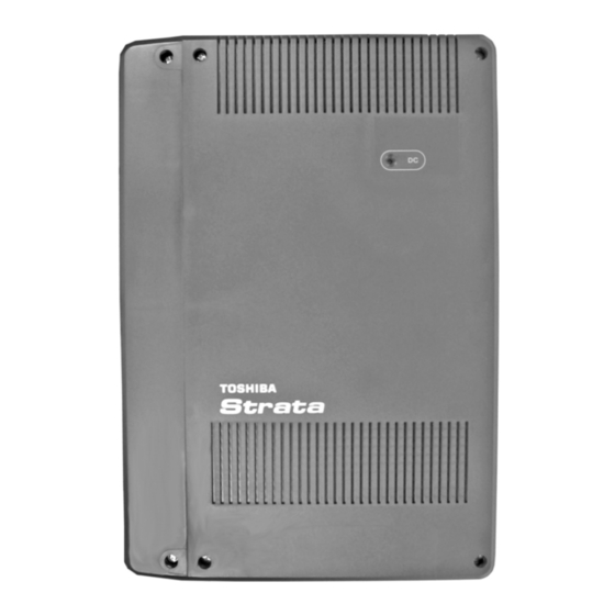
Page 18: Installing The Cix40 Cabinet
Cover Screws (6) All cover screws (6) must be removed before mounting the cabinet. DC Power LED Side Cover Base Cover Model: CHSU40A Strata CIX40 Label on edge of cabinet. Figure 1-9 CIX40 Cabinet Exterior 1-12 Strata CIX40 Installation & Maintenance 5/06... - Page 19 Figure 1-10 CIX40 Interior Method 2 Plaster Stud Board Hard Board (1/2 Inch Plywood) Base KSU 7114 Figure 1-11 CIX40 Cabinet Wall Mounting 8. Ground system according to “AC Power and Grounding Requirements” on page 1-10. 1-13 Strata CIX40 Installation & Maintenance 5/06...
-
Page 20: Pcb Installation
PCB Installation Overview Instructions The following is an overview for installing the Printed Circuit Boards (PCBs) into the Strata CIX40. After reading this section, proceed to the step-by-step instructions for each PCB. 1. Apply proper settings on the GMAU2 (motherboard Figure 1-14). - Page 21 CIX40 Installation Installing the CIX40 Cabinet GIPH1 GCTU2 removed for clarity. GVPH1 GVPH1 Card Stopper GMAU2 Refer Figure 1-13 on Page 1-16. Figure 1-12 GVPH1 and GIPH1 Locations 1-15 Strata CIX40 Installation & Maintenance 5/06...
- Page 22 CIX40 Installation Installing the CIX40 Cabinet GIPH1 and GCTU2 PCB Stopper GVPH1 Stopper Loosen two screws, remove stopper before inserting card. Replace Stopper, tighten screws. Figure 1-13 Card Stopper and Retainer 1-16 Strata CIX40 Installation & Maintenance 5/06...
- Page 23 Lit when SW1 is [ON], turned on and AC power or Reserve power is present. Dark when SW1 is [STANDBY], turned off. Terminal with screw Grounding for HPFB-6 external battery Grounding for CIX40 system, connect to Terminal with screw earth ground 1-17 Strata CIX40 Installation & Maintenance 5/06...
- Page 24 Table 1-6 GMAS (Sub-motherboard) Control/Indicator/ Type of Component Description Connector 44-pin DIN male GMAU2 interface connector Pin Jack DC-IN (DC15V) jack 44-pin DIN female GVPH1 interface connector GCTU2 interface 44-pin DIN female connector GIPH1 interface 1-18 Strata CIX40 Installation & Maintenance 5/06...
- Page 25 6. Replace the GVPH1 stopper and secure with the oridginal two screws. 7. Turn system power on. Note To program GVPH1, refer to Strata CIX40 Voice Processing Programming Manual and use UADM2 software. To restore the GVPH1 to the data that was stored on the GVPH1 on board RAM (see CAUTION! below) 1.
-
Page 26: Voice Mail And Telephone Lcd Prompts
1.Prompt language is set by SW1. The language set by the Admin PC has no effect. Table 1-8 Other Switch Settings on the GVPH1 Switch Position Function For using Admin PC - (Default setting) For use by Field Engineer Program update, latest- (Default setting) Program update, previous 1-20 Strata CIX40 Installation & Maintenance 5/06... -
Page 27: Remote Connection
9600 baud. CAUTION! Internal modems configured for COM ports 3 or 4 are not supported by UADM software. The UADM PC’s modem connects to the GVPH1 through User ID 993. 1-21 Strata CIX40 Installation & Maintenance 5/06... - Page 28 GCTU2 for GIPH1 operations. Reset switch Serial port HB LED Channel 8 Channel 7 Channel 6 Channel 5 Channel 4 Channel 3 LAN Port Channel 2 Channel 1 Figure 1-16 GIPH1 Card 1-22 Strata CIX40 Installation & Maintenance 5/06...
- Page 29 CIX40 Installation Installing the CIX40 Cabinet GIPH1 GVPH1 Card Retainer Note: GIPH1 passes under card stopper. 0001-cx40 Figure 1-17 GIPH1 / GCTU2 PCB Stopper 1-23 Strata CIX40 Installation & Maintenance 5/06...
- Page 30 SecureDigital slot on the GCTU2 (see Figure 1-18). Battery Jumper Heart Beat LED Secure Digital LED SecureDigital Card Slot BSIS Connector DC Power LED LAN Port Paging Relay Contact Figure 1-18 GCTU2 PCB 1-24 Strata CIX40 Installation & Maintenance 5/06...
- Page 31 CIX40 Back plane connector connector CD101 Processor operation indication (heartbeat) CD201 Secure Digital access indicator Green DC power indicator for CIX40 system. Shown on front cover (see Figure 1-9). P801 RJ45 Network interface port (LAN port) 1-25 Strata CIX40 Installation & Maintenance 5/06...
- Page 32 Carefully place the GCDU2 pins over the GMAU2 connectors (see Figure 1-12 Figure 1-19). Press down on the PCB to secure the pins to the connectors (see Table 1-11). Figure 1-19 GCDU2 PCB 1-26 Strata CIX40 Installation & Maintenance 5/06...
- Page 33 12-pin male connector GMAU2 interface 9-pin male connector 6-pin male connector P400 Interface for CO Line circuit (CO4) P500 Modular connector Interface for CO Line circuit (CO5) P600 Interface for CO Line circuit (CO6) 1-27 Strata CIX40 Installation & Maintenance 5/06...
- Page 34 Refer to Figure 1-20. GSTU1 Figure 1-20 GSTU1 PCB Table 1-12 GSTU1 Controls, Indicators, and Connectors Control/Indicator/ Type of Description Connector Component 12-pin male connector 9-pin male GMAU2 interface connector 3-pin male connector 1-28 Strata CIX40 Installation & Maintenance 5/06...
- Page 35 2 hr. 10 min. 6CO/16DKT - with GVPH1 1 hr. 2 hr. 1. Place the HPFB-6 directly below the Strata CIX40 Cabinet. See Figure 1-23 for minimum clearance requirements. A second HPFB-6 can be installed directly below the unit to supply backup reserve power.
- Page 36 Note The CIX40 Cabinet does not provide a battery charger, the HPFB-6 contains built-in batteries and a battery charger; therefore, do not connect any other type of batteries to the CIX40. Battery Cable BATT ON / Standby Switch Figure 1-22 HPFB-6 Connection 1-30 Strata CIX40 Installation & Maintenance 5/06...
- Page 37 CAUTION! Do not wrap the power cord around the AC adaptor. Excess cord should be gathered and secured with the supplied strap as shown in Figure 1-7. The cord bundle may be secured to the side of the adapter. 1-31 Strata CIX40 Installation & Maintenance 5/06...
-
Page 38: Digital Telephone Connection
CIX40 Installation Digital Telephone Connection 7257 Figure 1-24 AC Adapter Wiring Procedure Digital Telephone Connection The Strata CIX40 supports any Toshiba 2000, 3000 and 3200 -series digital telephones, including the DKT3207-SD telephone (shown right). The DKT3207-SD only works on the CIX40. -
Page 39: Loop Limits
CIX40 Installation Loop Limits Loop Limits This section provides the maximum loop lengths for connection of telephones, lines, peripheral equipment, and power supplies. The following information applies to only the Strata CIX40 system (see Table 1-14). Table 1-14 Digital Telephone/DIU/DDSS Console/ADM/Loop Limits... -
Page 40: Cix40 Secondary Protection
Recommended protectors are available in the fast Series 6 line from ONEAC Corp., Libertyville, Illinois 60048, (800) 327-8801. Install and test the secondary protectors precisely to the installation instructions of these manufacturer. 1-34 Strata CIX40 Installation & Maintenance 5/06... -
Page 41: Mdf Wiring
6 5 4 3 2 1 GCDU 2 3 4 5 MODULAR CORD 66M150 SPLIT BLOCK CO1~6 7262 GMAU NETWORK JACK: RJ14C MODULAR FIC: 02LS2 GCDU JACKS PIN-OUT Figure 1-27 MDF Wiring to CO Lines (GMAU2 and GCDU2) 1-35 Strata CIX40 Installation & Maintenance 5/06... -
Page 42: Gvph1 Administration Pc Connections
PC COM port GVPH RS232C Jack PC with GVPH XADM Software 7407_40 Strata CIX40 Serial Port Modular Pins (Data from GVPH) (Data to GVPH) (Data Set Ready from GVPH) (Data Terminal Ready to GVPH) (Carrier Detect from GVPH) -
Page 43: Station Loop Lengths
DKT with DADM3020 or DADM2020 (1 ADM) Battery Backup 165 ft. (50m) 500 ft. (151m) DKT with DADM3020 or DADM2020 (2 ADMs) Battery Backup 33 ft. (10m) 1000 ft. (303m) DDCB3A Battery Backup 165 ft. (50m) 1-37 Strata CIX40 Installation & Maintenance 5/06... -
Page 44: Cix40 Default Initialized Data
PDN DKT9~16 (Optional) DKT9 DKT10 DKT11 DKT12 DKT13 DKT14 DKT15 DKT16 VMID same as PDN Table 1-20 Program 204 Default Data In Program 204, all telephones are programmed as 20 buttons. 1-38 Strata CIX40 Installation & Maintenance 5/06... - Page 45 ANI and DNIS/DNIS/DID ANI or DNIS Notice Contents Underlined values are CIX100 default. Note: Class Equipment number is not required for CIX40 because CLID circuits are built-in and dedicated to each CO line. 1-39 Strata CIX40 Installation & Maintenance 5/06...
- Page 46 GMAU2 EQUIP 010101 010102 010103 010104 010105 010106 010107 010108 010401 Ext. Ext. Ext. Ext. Ext. Ext. Ext. Ext. Ext. FB19 VM ID VM MW FB22 Center Port Station FB35 Speed Dial Bins 1-40 Strata CIX40 Installation & Maintenance 5/06...
- Page 47 Table 1-29 Prog 580 – Voice Mail Data Assignment Default Data for GVPH1 INBAND / SMDI SMDI SMDI SMDI SMDI Note: In Program 209, the above Voice Mail ports are assigned to (distributed) Hunt Group 01. D. H. Pilot DN 250 1-41 Strata CIX40 Installation & Maintenance 5/06...
- Page 48 Table 1-33 Prog 304 Default Trunk Group Group Number Group Type 1 (Analog) Line Type 1 (CO) CO Service Type Table 1-34 Prog 306 Default Trunk Type Group Number Group Type 1 (Analog) Trunk Type 1 (CO) 1-42 Strata CIX40 Installation & Maintenance 5/06...
-
Page 49: Ip Default Data For Giph1 Card
Group Type 2 (ISDN) Line Type 2 (TIE) Private Service Type QSIG Table 1-37 Prog 306 Default Trunk Type Group Number Group Type 2 (ISDN) Trunk Type 2 (TIE) Service Type 2 (QSIG) 1-43 Strata CIX40 Installation & Maintenance 5/06... -
Page 50: Call Monitor
To talk to the caller during the recording, press Call Monitor. The recording stops and the LED turns solid red. The LCD display indicates the extension or line to which you are connected. 1-44 Strata CIX40 Installation & Maintenance 5/06... -
Page 51: Chapter 2 - Cix40 Ip Telephony
CIX40 IP Telephony This chapter introduces IP telephones and Strata Net IP on the Strata CIX40 system. It includes information specific to the GIPH1 card. The subjects of IP Telephony, in general, and IP Telephone installation are covered, in detail, in the Strata CIX and MAS Installation and Maintenance Manual. -
Page 52: Install The Giph1
2. Plug the other end of the LAN cable into a LAN or server jack refer to Figure 2-1. The GIPH1 cable is a straight-through cable. CIX40 Strat Net IP GCTU2 Router GIPH1 LIPU GIPH1 BIPU-Q MAS* *Optional Figure 2-1 IP LAN Connections Strata CIX40 Installation and Maintenance 7/06... -
Page 53: Install Ip Telephones
The IP Telephone (IPT) sets require external power. The power supply can be from the AC adapter included with the IPT or the LAN using a Power Over Ethernet (POE). POE must meet IEEE802.3af standard. Toshiba recommends the SMC6824MPE PoE switch. Refer to “Power over LAN” in the CIX and MAS Installation and Maintenance Manual. - Page 54 This is the last page of the document.