
Related Manuals for Fujitsu Primergy BX900 S2


Summary of Contents for Fujitsu Primergy BX900 S2
-
Page 1: Blade Server
Operating Manual - English PRIMERGY BX900 S2 Blade Server System Unit Operating Manual Edition December 2012... -
Page 2: Copyright And Trademarks
– The contents of this manual may be revised without prior notice. – Fujitsu assumes no liability for damages to third party copyrights or other rights arising from the use of any information in this manual. – No part of this manual may be reproduced in any without the prior written permission of Fujitsu. - Page 3 Before reading this manual For your safety This manual contains important information for safely and correctly using this product. Carefully read the manual before using this product. Pay particular attention to the accompanying manual "Safety Notes and Regulations" and ensure these safety notes are understood before using the product.
- Page 4 Please consult the sales staff of Fujitsu if intending to use this product for high safety use. Measures against momentary voltage drop This product may be affected by a momentary voltage drop in the power supply caused by lightning.
-
Page 5: Table Of Contents
Contents Introduction ......7 Concept and target groups for this manual ..7 Documentation overview . - Page 6 Contents Starting up and operation ....67 Control and display elements ....67 6.1.1 Front of system .
-
Page 7: Introduction
Introduction The PRIMERGY BX900 S2 system unit is a highly compact, energy-saving and scalable server system for installation in a 19-inch rack. The BX900 S2 system unit has space for up to 18 server and storage blades. With its advanced infrastructure modules, the BX900 S2 system unit offers the server blades a high level of connectivity and availability. -
Page 8: Documentation Overview
More information on your PRIMERGY BX900 S2 system unit can be found in the following documents: – "Quick Start Hardware - PRIMERGY BX900 S2 Blade Server" leaflet " は じ めにお読み く だ さ い -PRIMERGY BX900 S2 Blade Server" for the Japanese market (only included as a printed copy) –... - Page 9 Internet. The overview page showing the online documentation available on the Internet can be found using the URL (for EMEA market): http://manuals.ts.fujitsu.com. The PRIMERGY server documentation can be accessed using the Industry standard servers navigation option. For the Japanese market: Please refer to the following URL for the latest product manuals: http://jp.fujitsu.com/platform/server/primergy/manual/...
-
Page 10: Notational Conventions
Introduction Notational conventions The following notational conventions are used in this manual: Text in italics indicates commands or menu items. "Quotation marks" indicate names of chapters and terms that are being emphasized. describes activities that must be performed in the order Ê... -
Page 11: Functional Overview
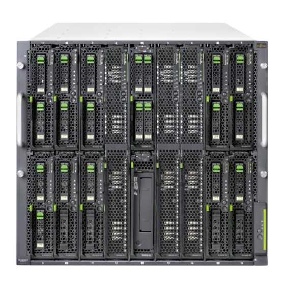
Functional overview This section provides information on the features and technical data of the PRIMERGY BX900 S2 system unit. Features Customer Self Service (CSS) The PRIMERGY Customer Self Service (CSS) concept enables you to identify and replace the affected component yourself in the case of certain error scenarios. - Page 12 Functional overview http://jp.fujitsu.com/platform/server/primergy/system/ (for the Japanese market) Server blades The PRIMERGY BX900 S2 system unit has 18 half height or 9 full height bays on the front for server or storage blades. 10 11 12 18 13 14 15 16...
- Page 13 Functional overview The following server blades are available for the BX900 S2 system unit. PRIMERGY BX920 S2 server blade ® ® Processor type Intel Xeon 5500 or 5600 series Processor quantity 1 - 2 Max. per system unit Memory slots Maximum memory capacity 144 GB PRIMERGY BX920 S3 server blade...
- Page 14 "PRIMERGY BX900 S2 System Unit Upgrade and Maintenance Manual". For further information on the server blades, see the relevant operating manuals.
- Page 15 Functional overview Storage blades Storage blades can be used to extend the internal storage capacity of the server blades. PRIMERGY SX910 S1 storage blade Storage media LTO tape drive Tape slots quantity Max. per system unit Installable in slots 2 - 17 - 7 - 10 - 18 - 15 Connected to server blade in the adjacent slot to the left or to the right...
- Page 16 Functional overview PRIMERGY SX980 S1 storage blade Storage media 2.5 inch HDD or SSD modules Disk slots quantity Max. per system unit Installable in slots 1/2 - 3/4 - 5/6 - 7/8 - 9/10 - 11/12 - 13/14 - 15/16 Connected to server blades with SAS mezzanine card via SAS...
- Page 17 Functional overview Connection blades The PRIMERGY BX900 S2 system unit has eight slots for connection blades on the back. Connection blades provide the installed server blades with connections to the Ethernet LAN as well as to SAN environments and SAS storage environments.
- Page 18 Functional overview Each pair of adjacent connection blade slots forms a so-called fabric. The following table shows how you can fill the fabrics and which network components of the server blades they are connected to: System unit Server blade Connection blade slots CB1: CB2: 1Gb Ethernet or...
- Page 19 Functional overview When filling the slots in fabrics 2, 3 and 4, also make sure the server blades are fitted with the appropriate mezzanine cards. For information about port assignment of connection blades and corresponding mezzanine cards, please refer to the "PRIMERGY BX900 S2 System Unit Upgrade and Maintenance Manual".
- Page 20 The stacking ports allow up to 8 SB11 connection blades to be switched together to form a so-called stack, see the "PRIMERGY BX900 S2 System Unit Upgrade and Maintenance Manual". 1 Gb Ethernet connection blades in slots CB3/4 (fabric 2), CB5/6 (fabric 3) and CB7/8 (fabric 4) only support server blades that are fitted with an 1 Gb Ethernet mezzanine card.
- Page 21 Functional overview Connection Blade 10 GbE Switch/IBP 18/8 18 internal 10-Gbit/s ports to the server blades 8 external 10-Gbit ports through SFP+ modules or active twinax cables (copper) Installable in all connection blade slots CB1/2 (fabric 1), CB3/4 (fabric 2) and CB5/6 (fabric 3) This connection blade can be used as a layer-2 switch or an Intelligent Blade Panel (IBP).
- Page 22 Functional overview Connection Blade Ethernet Pass Thru 10Gb 18/18 18 internal 1/10-Gbit/s ports to the server blades 18 external uplink ports at 10 Gbit/s and 1 Gbit/s link speed through SFP+/SFP modules Installable in connection blade slots CB1/2 (fabric 1), CB3/4 (fabric 2) and CB5/6 (fabric 3) 10 Gb Ethernet Pass Thru connection blades in slots CB3/4 (fabric 2) and CB5/6 (fabric 3) only support server blades that...
- Page 23 Functional overview Fibre Channel connection blades Fibre Channel connection blades only support server blades that are fitted with a Fibre Channel mezzanine card. Connection Blade 8Gb FC Switch 18/8 (Brocade BR5450) 18 internal 8-Gbit/s ports to the server blades 8 external ports through 8-Gb SFP+ modules or 4-Gb SFP modules Installable in slots CB3/4 (fabric 2) and CB5/6 (fabric 3) This connection blade is available in three license variants: –...
- Page 24 Functional overview 10 Gb Ethernet / DCB connection blades Connection Blade DCB SW 10Gb 18/6+6 18 internal 10-Gbit/s ports to the server blades 6 external 10-Gbit/s Data Center Bridging (DCB) capable ports through Brocade branded SFP+ modules or SFP+ Twinax cables 6 external FC ports through 8-Gb SFP+ modules or 4-Gb SFP modules Installable in slots CB 1/2 (fabric 1), CB3/4 (fabric 2) and CB5/6 (fabric 3)
- Page 25 Functional overview Infiniband connection blades Infiniband connection blades only support server blades that are fitted with an Infiniband mezzanine card. Connection Blade Infiniband Switch 40 Gb 18/18 18 internal 40-Gbit/s ports to the server blades 18 external 40-Gbit/s Infiniband connections through QSFP modules Installable in slots CB3/4 (fabric 2), CB5/6 (fabric 3) and CB7/8 (fabric 4) Connection Blades Infiniband Switch 40 Gb 18/18 only support...
- Page 26 (for the Japanese market) Management blade The PRIMERGY BX900 S2 system unit has slots for two redundant, hot-swap management blades with an integrated management solution for complete remote administration of the system. Supported programs The ServerView management blade is compliant with IPMI (Intelligent Platform Management Interface) 2.0.
- Page 27 The defective power supply unit can be replaced during operation (for further details see the "PRIMERGY BX900 S2 System Unit Upgrade and Maintenance Manual"). A combination of standard PSUs and HE PSUs in one BX900 S2 system unit is not allowed.
- Page 28 The configuration is redundant and offers hot-swap functionality (for more information, see the "PRIMERGY BX900 S2 System Unit Upgrade and Maintenance Manual"). High level of availability and data security...
-
Page 29: System Unit Specification
Functional overview System unit specification This section explains the specifications for the system unit. The specifications for this system unit are liable to be updated without any notice. Please be forewarned. Interfaces (Management Blade) USB connectors Serial 1 (9-pin) 1 x serial RS-232-C Management LAN (RJ- Management LAN ports for blade server management (2 x 1 Gbit/s Ethernet) - Page 30 Functional overview Dimensions / Weight Dimensions 482.6 mm (Bezel) / 445 mm (Body) x 778 mm x 438 mmm Height Unit Rack 10 U Weight Up to 204 kg Weight notes Weight may vary depending on actual configuration Rack mounting kit Included Ambient conditions Environment class 3K2...
- Page 31 Functional overview Electrical data (standard PSU) Rated voltage range 100 - 240 V Frequency 50 Hz - 60 Hz Max. rated current 230 V / 11.6 A (EMEA market) 100-120 V / 12 A (Japanese market) 200-240 V / 13.5 A (Japanese market) Effective power 3200 W (230 V) (EMEA market) 1600 W (100 V) (EMEA market)
- Page 32 Functional overview Compliance with regulations and standards Product safety and ergonomics International IEC 60950-1 2ed. Europe Safety EN 60950-1 2ed. EN 50371 EN 50392 Ergonomics ISO 9241-3 EN 2941-3 EK1-ITB 2003:2007 USA / Canada CSA-C22.2 No. 60950-1-07 2ed. UL 60950-1 2ed. Taiwan CNS 14336 China...
-
Page 33: Installation Steps, Overview
67). Ê Install the server blades and storage blades in the slots on the front of the system unit (see the "PRIMERGY BX900 S2 System Unit Upgrade and Maintenance Manual"). Ê Install the connection blades in the slots on the back of the system unit (see the "PRIMERGY BX900 S2 System Unit Upgrade and Maintenance... - Page 34 Installation steps, overview Operating Manual BX900S2...
-
Page 35: Important Information
Important information CAUTION! Before installing and starting up a device, please observe the safety instructions listed in the following section. This will help you to avoid making serious errors that could impair your health, damage the device and endanger the data base. Safety instructions The following safety instructions are also provided in the manual "Safety Notes and Regulations"... - Page 36 Important information Wait until the device has acclimatized to room temperature and is absolutely dry before starting it up. Material damage may be caused to the device if this requirement is not observed. Transport the device only in the original packaging or in packaging that ●...
- Page 37 Important information Route the cables in such a way that they do not create a potential hazard ● (make sure no-one can trip over them) and that they cannot be damaged. When connecting the server, refer to the relevant instructions in this manual. Never connect or disconnect data transmission lines during a storm (risk of ●...
- Page 38 Important information Devices inside the server remain hot after shutdown. Wait for a while after ● shutdown before installing or removing internal options. The circuit boards and soldered parts of internal options are exposed and ● can be damaged by static electricity. To ensure reliable protection, if you are wearing an earthing band on your wrist when working with this type of module, connect it to an unpainted, non-conducting metal part of the system.
- Page 39 Important information Working with optical disk drives and media When working with optical disk drives, these instructions must be followed. CAUTION! Only use CDs/DVDs/BDs that are in perfect condition, in order to ● prevent data loss, equipment damage and injury. Check each CD/DVD/BD for damage, cracks, breakages etc.
- Page 40 Important information Do not contaminate the CD/DVD/BD surface with fingerprints, oil, ● dust, etc. If dirty, clean with a soft, dry cloth, wiping from the center to the edge. Do not use benzene, thinners, water, record sprays, antistatic agents, or silicone-impregnated cloth. Be careful not to damage the CD/DVD/BD surface.
- Page 41 Important information Modules with Electrostatic-Sensitive Devices Modules with electrostatic-sensitive devices are identified by the following sticker: Figure 3: ESD label When you handle components fitted with ESDs, you must always observe the following points: Switch off the system and remove the power plugs from the power outlets ●...
- Page 42 Only unpack the system unit at the place where you want to set it up. Ask someone for help with carrying the system unit. Because the ● PRIMERGY BX900 S2 system unit is large and heavy, at least 3 people are needed. Before lifting the system unit, remove all server blades, storage blades, ●...
-
Page 43: Ce Conformity
Important information Before connecting or disconnecting cables, read the notes in the chapter ● "Important Notes" in the technical manual for the relevant rack. The technical manual for the rack is supplied with the rack. The rack must be connected to the mains by an authorized specialist ●... - Page 44 Consult the dealer or an experienced radio/TV technician for help. ● Fujitsu is not responsible for any radio or television interference caused by unauthorized modifications of this equipment or the substitution or attachment of connecting cables and equipment other than those specified by Fujitsu. The correction of interferences caused by such unauthorized modification, substitution or attachment will be the responsibility of the user.
-
Page 45: Environmental Protection
Important information Environmental protection Environmentally-friendly product design and development This product has been designed in accordance with the Fujitsu standard for "environmentally friendly product design and development". This means that key factors such as durability, selection and labeling of materials, emissions, packaging, ease of dismantling and recycling have been taken into account. - Page 46 Details regarding the return and recycling of devices and consumables within Europe can also be found in the "Returning used devices" manual, via your local Fujitsu branch or from our recycling center in Paderborn: Fujitsu Technology Solutions Recycling Center D-33106 Paderborn Tel.
-
Page 47: Hardware Installation
Hardware installation CAUTION! Follow the safety instructions in the chapter "Important information" ● on page Do not expose the server to extreme environmental conditions (see ● "Ambient conditions" on page 30). Protect the server from dust, humidity and heat. Make sure that the server is acclimatized for the time indicated in this ●... -
Page 48: Unpacking The System Unit
Hardware installation Unpacking the system unit CAUTION! Make sure you observe the safety notes in chapter "Important information" on page The system unit must always be lifted or carried by at least three people. (For the Japanese market, please refer to " 安全上のご注意 "). Only unpack the system unit at the place where you want to set it up. -
Page 49: Installing/Removing The System Unit
Hardware installation Installing/removing the system unit CAUTION! At least three people are needed to lift the system unit. (For the Japanese market, please refer to " 安全上のご注意 ".) For configurations below 32 kg: At least two people are needed to lift the system unit. - Page 50 Please observe the safety information and notes on rack mounting in chapter "Important information" on page Fujitsu rack systems The rack systems from Fujitsu support the installation of PRIMERGY servers: – PRIMECENTER rack – PRIMECENTER M1 rack – DataCenter rack –...
-
Page 51: Installation In Primecenter/Datacenter Rack
Hardware installation 5.2.1 Installation in PRIMECENTER/DataCenter rack For installation in a PRIMECENTER/DataCenter rack, the following parts are required: – One 10-HU support bracket (option for asymmetrical rack like PRIMECENTER/DataCenter rack) – Two carrier rails (right and left rail) – Two holding-down clamps –... - Page 52 Hardware installation Figure 4: Position of the system unit in the rack - front support uprights Position of M5 screws including plugwashers Position of cage nuts Carrier rails Operating Manual BX900S2...
- Page 53 Hardware installation Figure 5: Position of the system unit in the rack - rear support uprights Position of centering screws Position of the insert knob Carrier rails Holding-down clamps Ê Clarify the position of the system unit in the rack. Ê...
- Page 54 Hardware installation When mounting the left carrier rail in the PRIMECENTER/DataCenter rack, the optional support bracket must first be mounted on the rear left support upright flush with the bottom edge of the device. The support bracket is not necessary for the symmetrical rack. Ê...
- Page 55 Hardware installation Ê Fasten the holding-down clamp at the upper end of the support bracket using two centering screws, see (1) in figure For the symmetrical racks: The support bracket is not necessary for the symmetrical rack. Please position the holding-down clamp directly on the support upright.
- Page 56 Hardware installation Ê Fasten the carrier rail at the lower end of the support bracket using three centering screws (2). Ê Position the carrier rail in the front left support upright. Ê Fasten the carrier rail to the front support upright (3) using three M5 screws including plugwashers.
-
Page 57: Installing/Removing The System Unit
Removal of these components is described in the "PRIMERGY BX900 S2 System Unit Upgrade and Maintenance Manual". If there is no PRIMERGY BX900 S2 System Unit Upgrade and Maintenance Manual available on ServerView Suite DVD2, please refer to the following URL: http://manuals.ts.fujitsu.com... - Page 58 Hardware installation Figure 9: Placing the system unit on the rack rails Before inserting the system unit in the rack ensure the stability of the rack. Ê Lift the back end of the system unit onto the carrier rails in the rack. Ê...
- Page 59 57. Installation of these components is described in the "PRIMERGY BX900 S2 System Unit Upgrade and Maintenance Manual". CAUTION! Incorrect fitting of the system unit may lead to serious errors.
-
Page 60: Connecting Devices To The System Unit
Hardware installation Connecting devices to the system unit On the back of the system unit are the ports for the network connection and the administration of the blade server. Ports on the back of the system unit CB 1 CB 2 CB 3 CB 4 CB 5... -
Page 61: Cable Routing
CAUTION! Read the information on determining how many power supply units ● are required (see the "PRIMERGY BX900 S2 System Unit Upgrade and Maintenance Manual"). The power supply units automatically adjust to a mains voltage ●... - Page 62 Hardware installation The HE power supply units may only be connected to NEMA L6-20 or IEC 60320-C20 sockets. Always connect the cable first to the power supply unit and then to the ● mains. Ê First connect the insulated C19 connector of the power cable to the power supply units of the system unit, and then plug the connector into the UPS, power distribution unit or an external socket.
- Page 63 Hardware installation redundancy is supported; the system continues to run if one source fails, provided the remaining 3 power supplies are sufficient to deliver the required power. With 4 power supply units, you must connect units 2 and 3 to the first source (phase) and units 5 and 6 to the second.
-
Page 64: Using Cable Ties
Hardware installation 5.4.1 Using cable ties If you wish, you can secure the power cable with a cable tie to prevent the C19 connector from being pulled out of the server accidentally. The cable tie is included in the accessories pack that is delivered together with the server. Figure 13: Using cable ties Ê... -
Page 65: Notes On Connecting/Disconnecting Cables
Hardware installation Notes on connecting/disconnecting cables CAUTION! Always read the documentation supplied with the device you wish to connect. Never connect, or disconnect cables during a thunderstorm. Never pull on a cable when disconnecting it. Always take hold of the cable by the plug. - Page 66 Hardware installation Information for ensuring electromagnetic compatibility All data and signal cables must have sufficient shielding. The use of cable type S/FTP Cat5 or better is recommended. Use of unshielded or badly shielded cables may lead to increased emission of interference and/or reduced fault-tolerance of the device.
-
Page 67: Starting Up And Operation
Starting up and operation CAUTION! Follow the safety instructions in chapter "Important information" on page Control and display elements 6.1.1 Front of system The BX900 S2 system unit has a fold-out ServerView local service panel on the front. It is controlled by the management blade and is used for local diagnostics and administration of the blade server. - Page 68 Starting up and operation Figure 15: Locking the ServerView local service panel CAUTION! Press the touch point (see arrow) of the ServerView local service panel before you push it back into the frame of the system unit. Operating Manual BX900S2...
- Page 69 Starting up and operation Figure 16: Control and display elements on the front of the ServerView local service panel CSS indicator Power indicator Global Error indicator ID indicator ID button Navigation buttons for the LocalView menu system On/Off button Operating Manual BX900S2...
-
Page 70: Control Elements
Starting up and operation 6.1.1.1 Control elements On/Off button When the system is switched off, it can be switched on again by pressing the On/Off button. When the system is operating, pressing the On/Off button will switch off the system. CAUTION! Risk of loss of data! The On/Off button does not disconnect the server from the... - Page 71 Starting up and operation Global Error indicator (orange) – Lights up orange if a prefailure event has been detected that requires (precautionary) service intervention. – Flashes orange if an error was detected that requires service intervention. – Does not light up if there is no critical event. If the event is still acute after a power cycle, the indicator is activated after the restart.
-
Page 72: Id Card
Starting up and operation 6.1.1.3 ID card You can pull out the ID card (see figure 17) as far as it will go and push it back in again. Figure 17: ID card in system unit The ID card contains various system information, such as the product name, serial number and order number. -
Page 73: Back Of System
Starting up and operation 6.1.2 Back of system 6.1.2.1 Control and display elements on the management blade 1 2 3 9 10 11 Figure 18: Control and display elements on the management blade Status indicator (yellow) Lights up when the management blade is active (master) Blinks when the management blade is defective. - Page 74 Starting up and operation Global Error indicator (orange) – Lights up orange if a prefailure event has been detected that requires (precautionary) service intervention. – Flashes orange if an error was detected that requires service intervention. – Does not light up if there is no critical event. If the event is still acute after a power cycle, the indicator is activated after the restart.
- Page 75 Starting up and operation 7, 9 LAN link indicators (Management LAN ports) Lights up green if a LAN connection exists. Does not light up if no LAN connection exists. 8, 10 LAN activity indicators (Management LAN ports) Flashes yellow when a LAN transfer is in progress. Does not light up if no LAN transfer.
-
Page 76: Indicators On The Hot-Plug Power Supply Units
Starting up and operation 6.1.2.2 Indicators on the hot-plug power supply units Figure 19: Indicators on the hot-plug standard power supply unit Figure 20: Indicators on the hot-plug HE power supply unit Error indicator for fan module 1 (orange) Lights up if fan module 1 is defective. Mains power indicator (two-color) Flashes green when the system unit is switched off but still connected to the mains (standby mode). -
Page 77: Indicators On The Hot-Plug Fans
Starting up and operation Error indicator for fan module 2 (orange) Lights up if fan module 2 is defective. The following events are detected as predictable errors: The temperature is very high. The power consumption is very high. The current strength is very high. 6.1.2.3 Indicators on the hot-plug fans 1 2 3... -
Page 78: Indicators And Connectors Of The Connection Blades
Starting up and operation 6.1.3 Indicators and connectors of the connection blades 6.1.3.1 Connection Blade GbE Switch/IBP 18/6 (SB6) Figure 22: Connection Blade GbE Switch/IBP 18/6 Status indicator (green/orange) Lights up green: Power supply is supplied to the connection blade Lights up Switch error orange:... -
Page 79: Connection Blade Gbe Switch/Ibp 36/12 (Sb11A)
Starting up and operation 6.1.3.2 Connection Blade GbE Switch/IBP 36/12 (SB11A) Figure 23: Connection Blade GbE Switch/IBP 36/12 ID indicator (blue) Lit: ID indicator was activated via the management blade Dark: Normal operation Status indicator (green/orange) Lights up green: power supply is supplied to the connection blade. Dark: power supply is not supplied to the connection blade. - Page 80 Starting up and operation 1-Gbit Ethernet ports (8x, RJ45 with two integrated LAN status LEDs each) LAN transfer rate (green/orange) Lights up LAN transfer rate 1 Gbit/s orange: Lights up green: LAN transfer rate 100 Mbit/s Dark: LAN transfer rate 10 Mbit/s LAN connection indicator (green) Lit: LAN connection available...
-
Page 81: Connection Blade Gbe Switch/Ibp 36/8+2 (Sb11)
Starting up and operation 6.1.3.3 Connection Blade GbE Switch/IBP 36/8+2 (SB11) 1 2 3 4 5 Figure 24: Connection Blade GbE Switch/IBP 36/8+2 Status indicator (green/orange) Lights up green: Power supply is supplied to the connection blade Flashes orange: Connection blade error Dark: Power supply is not supplied to the connection blade ID indicator (blue) - Page 82 Starting up and operation HiGig/HiGig+ connection (CX4) for stacking (2x), for detailed information see the "PRIMERGY BX900 S2 System Unit Upgrade and Maintenance Manual" 10-Gbit Ethernet ports for SFP+ modules for connecting fiber-optic or copper cables (with two integrated status LEDs each)
-
Page 83: Connection Blade 10 Gbe Switch/Ibp 18/8
Starting up and operation 6.1.3.4 Connection Blade 10 GbE Switch/IBP 18/8 1 2 3 Figure 25: Connection Blade 10 GbE Switch/IBP 18/8 Status indicator (green/orange) Lit green: Power supply is supplied to the connection blade Flashes Connection blade error alternately green/orange: Dark: Power supply is not supplied to the connection blade... - Page 84 Starting up and operation 10-Gbit Ethernet ports for SFP+ modules for connection of fiber-optic cables or for active twinax copper cables (8x, each with two integrated status LEDs) 4 (ERR) Error indicator (orange) Dark: No SFP+ module error or SFP+ module not installed Lit: SFP+ module error Flashes:...
-
Page 85: Connection Blade Ethernet Pass Thru 10Gb 18/18
Starting up and operation 6.1.3.5 Connection Blade Ethernet Pass Thru 10Gb 18/18 Figure 26: Connection Blade Ethernet Pass Thru 10Gb 18/18 ID indicator (blue) Lit: ID indicator was activated via the management blade Status indicator (green/orange) Lit green: Power is supplied to the connection blade Flashes orange: Connection blade error Dark:... -
Page 86: Connection Blade 8Gb Fc Switch 18/8
Starting up and operation 6.1.3.6 Connection Blade 8Gb FC Switch 18/8 1 2 3 Figure 27: 8-Gb FC Switch Connection Blade 18/8 ID indicator (blue) Lit: ID indicator was activated via the management blade Health indicator (green/orange) Controlled by the management blade Reset button Status indicator (green/orange) Dark:... -
Page 87: Connection Blade 8Gb Fc Pass Thru 18/18
Starting up and operation 6.1.3.7 Connection Blade 8Gb FC Pass Thru 18/18 Figure 28: 8-Gb FC Pass Thru Connection Blade 18/18 ID indicator (blue) Lit: ID indicator was activated via the management blade Status indicator (green/orange) Dark: Connection blade is powered off Lights up green: Connection blade is powered on, status OK Flashes orange:... -
Page 88: Connection Blade Dcb Sw 10Gb 18/6+6
Starting up and operation 6.1.3.8 Connection Blade DCB SW 10Gb 18/6+6 Figure 29: Connection Blade DCB SW 10Gb 18/6+6 External 10 Gb Ethernet ports (6x) Ports for Brocade branded Ethernet SFP+ 10 Gbit/s modules or SFP+ Twinax cables External 8 Gb FC ports (6x) Ports for Brocade branded FC SFP+ 8Gbit/s modules or SFP 4Gbit/s modules Status indicators for external Ethernet ports (green/orange) Dark:... - Page 89 Starting up and operation ID indicator (blue) Lit: ID indicator was activated via the management blade Health indicator (green/orange) Dark: Connection blade is powered off or power has failed Lights up green: Connection blade is running Flashes orange Connection blade has failed Status indicator (green/orange) Dark: Connection blade is shut down and powered off normally...
-
Page 90: Connection Blade Fex B22F 10Gb (Cisco)
Starting up and operation 6.1.3.9 Connection Blade FEX B22F 10Gb (Cisco) Figure 30: Connection Blade FEX B22F 10Gb (Cisco) External 10GbE ports (8x) to connect to the Nexus parent switch Ports for Cisco branded copper Twinax cables, Fabric Extender Transceivers (FET), or other standard 10 Gigabit Ethernet optics such as 10Gbase-SR, 10Gbase-LR, and 10Gbase-ER Service port (only for diagnostic purposes) -
Page 91: Connection Blade Infiniband Switch 40 Gb 18/18
Starting up and operation 6.1.3.10 Connection Blade Infiniband Switch 40 Gb 18/18 Figure 31: Connection Blade Infiniband Switch 40 Gb 18/18 Status indicator (green/yellow) Lights up green: Power supply is supplied to the connection blade Flashes yellow: Switch error ID indicator (blue) Lit: ID indicator was activated via the management blade Physical link status indicator of the external IB ports (green) -
Page 92: 6.1.3.11 Connection Blade Infiniband Switch 56 Gb 18/18 Fdr
Starting up and operation 6.1.3.11 Connection Blade Infiniband Switch 56 Gb 18/18 FDR Figure 32: Connection Blade Infiniband Switch 56 Gb 18/18 FDR Status indicator (green/yellow) Lights up green: Power supply is supplied to the connection blade Flashes yellow: Switch error ID indicator (blue) Lit: ID indicator was activated via the management blade... -
Page 93: Connection Blade Sas Switch 6 Gb 18/6
Starting up and operation 6.1.3.12 Connection Blade SAS Switch 6 Gb 18/6 Figure 33: Connection Blade SAS Switch 6 Gb 18/6 Status indicator (green/orange) Lights up green: Power supply is supplied to the connection blade Lights up Switch error orange: Dark: Power supply is not supplied to the connection blade ID indicator (blue) -
Page 94: Switching The System Unit On/Off
Before switching the system unit on using the On/Off button, the ● PRIMERGY BX900 S2 system unit must be connected to the power supply for at least a minute. If you switch on the system unit and the connected monitor only ●... - Page 95 Starting up and operation Ê To immediately shut down all server blades, press the On/Off button on the front of the system unit (position 4 in figure 16 on page 69) for 10 seconds. All server blades are switched off immediately. Other ways to shut down the system unit –...
-
Page 96: Configuring Management Blades
Starting up and operation Configuring management blades The two redundant management blades form the central interface for administration of the system unit and all components therein. This section explains how to do the initial configuration of the management blades. For more information on administration of the blade server, see the manual "PRIMERGY BX900 Blade Server Systems ServerView Management Blade S1 User Interface Description". - Page 97 Starting up and operation The wizard guides you step by step through the menus, in which you make the necessary settings for putting the blade server into operation. You operate the wizard with the Previous, Next, and Cancel buttons. The Finish button closes it. However, you cannot close the wizard until you have defined the following default settings: –...
- Page 98 Starting up and operation Ident. Identification Settings (1) Assign a name for the chassis. – System Name Assign a name for the rack where the chassis resides. – Rack Name Identification Settings (2) Assign a contact person for the system. –...
- Page 99 Starting up and operation Network If DHCP is activated (default), the obtained network data is displayed. Otherwise you can specify the network data manually: Management LAN Settings (1) IPv4 settings – IP Address is assigned by DHCP – Assign IP Address manually: –...
- Page 100 Starting up and operation Power Power Settings Assign the Power Supply Redundancy Mode and the Dynamic Mode. – PSU Redundancy (No Redundancy) – PSU Dynamic Mode (ON) Power Settings (2) If required specify the Power Consumption Budget. – PSU Consumption Budget enable –...
- Page 101 Starting up and operation Save Clicking the Save button saves and applies the settings in the management blade. With the Previous button you can go back and change parameters. You save the changed configuration with the Save button. Save Settings All necessary configurations are done.
-
Page 102: Cleaning The System Unit
Starting up and operation Cleaning the system unit CAUTION! To clean the system unit, first switch it off and unplug the power plug(s) from the grounded power outlet(s). The housing interior of the system unit should only be cleaned by authorized, qualified personnel. -
Page 103: Property And Data Protection
Property and data protection The blade server is protected against unauthorized access by the lockable rack door. To protect the system and data internally against unauthorized access, you can activate the security functions of the management blade. For more information, see the manual "PRIMERGY BX900 Blade Server Systems ServerView Management Blade S1 User Interface Description". - Page 104 Property and data protection Operating Manual BX900S2...
-
Page 105: Troubleshooting And Tips
Troubleshooting and tips CAUTION! Follow the safety instructions in the "Safety notes and regulations" manual or " 安全上のご注意 " and in chapter "Important information" on page If a fault occurs, attempt to resolve it using the measures described: – in this chapter, –... -
Page 106: Front Or Back Error Led Flashes Orange
Ê Check the status of the power supply unit and/or the fan-failure LEDs to identify the defective module and replace it (see the "PRIMERGY BX900 S2 System Unit Upgrade and Maintenance Manual"). One of the fans in the fan module has failed... -
Page 107: System Switches Itself Off
Troubleshooting and tips System switches itself off Server Management has detected an error Ê Check the error list of System Event Log in ServerView Operations Manager or in the management blade web interface, and attempt to eliminate the error. Operating Manual BX900S2... - Page 108 Troubleshooting and tips Operating Manual BX900S2...