
Related Manuals for Philips LBB 1360


Summary of Contents for Philips LBB 1360
- Page 1 SM 40 Surveillance Centre LBB 1360 & LBB1370 Philips Communication & Security Systems...
-
Page 3: Table Of Contents
SYSTEM UNPACKING AND INSTALLATION Introduction SM 40 BASIC SURVEILLANCE CENTRE Basic System - BS LBB 1370 Extension Frame - EF LBB 1360 OPERATING AND PROGRAMMING THE SM40 SURVEILLANCE CENTRE Central Processor Card - CPC Display and Keyboard - DK 4.2.1 Display readout SM40 Programmng 4.3.1... -
Page 4: Introduction
1. GENERAL INTRODUCTION SM40 SURVEILLANCE CENTRE (maximum system layout) -
Page 5: Introduction
The possibility also exists to automatically switch in a spare amplifier in place of an amplifier which becomes faulty. A pilot tone signal is generated which is inserted into the Test inputs of Philips SQ45 power amplifier range. The Surveillance Centre is able to scan for the presence of this signal in up to 4096 monitoring devices, located in strategic places (at amplifier outputs, loudspeaker cabling junction boxes, inside loudspeaker... - Page 6 2. UNPACKING AND INSTALLATION SURVEILLANCE BASIC SYSTEM LBB 1370 RS 232 connection PE 1141 FRONT TOP VIEW INTERCONNECTION BOARDS 1268/10 1141/52 ERROR ERROR TEST SIGNALS TEST LINES OUTPUT INPUT TERMINATION BOARDS (REAR VIEW)
- Page 7 2. UNPACKING AND INSTALLATION SM40 Surveillance Centre - Unpacking and installation In order to ensure that your SM40 Surveillance Centre functions properly, please follow these few simple instructions after unpacking your unit. Carefully check the enclosed system components for physical damage caused during shipping. Any complaints should be made immediately to the shipping company.
- Page 8 3. SM 40 BASIC SYSTEM AND EXTENSION FRAME SURVEILLANCE BASIC SYSTEM LBB 1370 Error Printer error indication System error External error LSB/ASB error General error Communication & 8x128 Power supply LSBs RS232 1268/10 1141/52 ERROR ERROR ERROR TEST SIGNALS TEST LINES OUTPUT OUTPUT INPUT...
- Page 9 (lamps, buzzers, etc.) when an error occurs. When a centre’s requirement exceed the facilities available in the Surveillance Basic System, further circuit cards (plus the extension frames LBB 1360 necessary to accomodate them) are ordered, expanding the system to meet specific application needs.
- Page 10 3. SM 40 BASIC SYSTEM AND EXTENSION FRAME SURVEILLANCE BASIC SYSTEM LBB 1370 Plus 1 EXTENSION FRAME LBB 1360 INTERCONNECTION BOARD WIRING AS VIEWED FROM REAR OF RACK UNIT PE 1268/10 PE 1141/52 TEST SIGNALS TEST SIGNALS TEST LINES TEST LINES...
-
Page 11: Extension Frame - Ef
Control Relay Cards and Surveillance Switch Cards. When the number of terminations boards required in an SM40 system exceeds the amount of space offered in this single rack frame, Extension Frame LBB 1360, is available. Units included with Extension Frame LBB 1360:... - Page 12 3. SM 40 BASIC SYSTEM AND EXTENSION FRAME SURVEILLANCE BASIC FRAME +15V supply & comm Pilot-tone Error RS232 supply PE1268/10 PE1141/50 Supply for Supply for surveillance boards eurocards 220 V DATA BUS ADDRESS BUS CONTROL BUS RS232 DISPLAY MICRO- I/O BOARD BUFFER PROCESSOR EPROM...
-
Page 13: Operating And Programming The Sm40 Surveillance Centre
4. OPERATING AND PROGRAMMING THE SM40 SURVEILLANCE CENTRE Central Processor Card - CPC Eurocard 10 x 22 cm with an ‘a b’ connector (2 x 32). A microprocessor which can scan over 4000 monitoring devices, and activate more than 100 relays, via the communication line. At the heart of the SM40 Surveillance Centre is the Central Processor Card (CPC). -
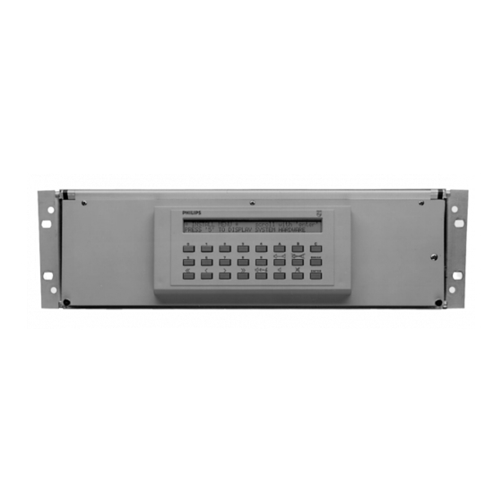
Page 14: Display And Keyboard - Dk
4. OPERATING AND PROGRAMMING THE SM40 SURVEILLANCE CENTRE DISPLAY & KEYBOARD * * * SM40 SURVEILLANCE SYSTEM * * * DAY:XX-XX TIME:XX:XX Break Mute Enter Grey shaded keys are functional in the programming mode. i.e USER MENU, INSTALLER MENU & SERVICE MENU DISPLAY READOUTS AFTER ENTERING 'USER-MENU' PASSWORD (9, 6, ENTER) >WELCOME TO SURVEILLANCE PROGRAMMING<... -
Page 15: User Programming Menu 3
4. OPERATING AND PROGRAMMING THE SM40 SURVEILLANCE CENTRE Display and Keyboard A programming tool, containing a keyboard for user key assignment and a display which shows the sequence of programming. Mounted in the front panel of the rack unit. Users of the SM40 Surveillance Centre are able to program and make changes to the functions of their system, quickly and easily, with the aid of the Display And Keyboard. - Page 16 4. OPERATING AND PROGRAMMING THE SM40 SURVEILLANCE CENTRE 4.2.1 Display readout During the remainder of this chapter, specific contexts (status) and user actions are shown in the left column, and possible display results are shown in the right column. Characters between quotes (e.g. ‘Key’) denote keyboard inputs, and occurrances of in any displays shown in the right column denote information which is dependant on the system configuration, or entered by the user.
- Page 17 4. OPERATING AND PROGRAMMING THE SM40 SURVEILLANCE CENTRE The printer produces a listing of errors as follows: <ERROR> DATE:XX-XX TIME:XX:XX ZONE:XX UNIT:XXX <ERROR> DATE:XX-XX TIME:XX:XX ZONE:XX UNIT:XXX <ERROR> DATE:XX-XX TIME:XX:XX ZONE:XX UNIT:XXX <ERROR> DATE:XX-XX TIME:XX:XX ZONE:XX UNIT:XXX <ERROR> DATE:XX-XX TIME:XX:XX ZONE:XX UNIT:XXX If the <ERROR>...
- Page 18 4. OPERATING AND PROGRAMMING THE SM40 SURVEILLANCE CENTRE SM40 USER PROGRAMMING Specific contexts (status) and user actions are shown in the left column, and possible display results are shown in the right column. Characters between quotes (e.g. ‘Key’) denote keyboard inputs, and occurrances in any displays shown in the right column denote information which is dependant on the system configuration, or entered by the user.
- Page 19 4. OPERATING AND PROGRAMMING THE SM40 SURVEILLANCE CENTRE Status / Action Result / Remarks (Continued from previous page...) PRINTER NOT READY; PLEASE CHECK Printing will begin when the printer problem has been solved. Pressing ‘Break’ will return the system back to display the Main Menu.
-
Page 20: Installer Programming Menu
4. OPERATING AND PROGRAMMING THE SM40 SURVEILLANCE CENTRE 4.3.2 SM40 SURVEILLANCE INSTALLER PROGRAMMING MENU Status / Action Result / Remarks To enter the INSTALLER programming mode, press keys ‘8’, ‘1’, followed by the > WELCOME TO SURVEILLANCE PROGRAMMING < ‘Enter’ key. Ther display shows: >>... - Page 21 4. OPERATING AND PROGRAMMING THE SM40 SURVEILLANCE CENTRE SM40 SURVEILLANCE INSTALLER PROGRAMMING MENU Status / Action Result / Remarks After pressing ‘6’ the display shows: SCANNING ZONE:XX UNIT:XXX All the relevant zones will be scanned and the units present will be stored in memory.
- Page 22 4. OPERATING AND PROGRAMMING THE SM40 SURVEILLANCE CENTRE SM40 SURVEILLANCE INSTALLER PROGRAMMING MENU Status / Action Result / Remarks The display shows the following: *INSTALL MENU* Scroll with 'ENTER' PRESS '8' TO SHOW ALL UNITS Display after pressing ‘8’. DISPLAY OF ALL UNITS FOUND PRESS '1' FOR PRINTER;...
- Page 23 4. OPERATING AND PROGRAMMING THE SM40 SURVEILLANCE CENTRE SM40 SURVEILLANCE INSTALLER PROGRAMMING MENU Status / Action Result / Remarks The scanning of a priority zone will be indicated by an ‘asterix’ in the upper right corner of the display. After entering the ‘interval time’ and after pressing ‘Enter’ the display will repeat the zone number request.
- Page 24 4. OPERATING AND PROGRAMMING THE SM40 SURVEILLANCE CENTRE SM40 SURVEILLANCE INSTALLER PROGRAMMING MENU Status / Action Result / Remarks The display shows the following: *INSTALL MENU* Scroll with 'ENTER' PRESS 'C' TO CLEAR ALL MEMORY Because this program clears the complete memory, caution must be taken. The display after pressing ‘C’...
- Page 25 4. OPERATING AND PROGRAMMING THE SM40 SURVEILLANCE CENTRE This page has been left blank intentionally...
- Page 26 5. SM40 SURVEILLANCE CENTRE MODULES BOARD MOUNTED IN SURVEILLANCE BASIC FRAME...
-
Page 27: Interconnection Board - Ib
5. SM40 SURVEILLANCE CENTRE MODULES Interconnection board (IB) Interconnection board for 10 SM40 Eurocards. Eurocard pressfit a + b (2 x 32) connectors. Mounted at the rear of the 19-inch rack frame. In any sophisticated communications system, convenient and dependable interconnection of the various component units is vital. - Page 28 5. SM40 SURVEILLANCE CENTRE MODULES...
- Page 29 5. SM40 SURVEILLANCE CENTRE MODULES DETAILED VIEW OF INTERCONNECTIONS TO EXTERNSION FRAME TO PSU No.1 TO EXTERNSION FRAME TO EXTERNSION FRAME...
- Page 30 5. SM40 SURVEILLANCE CENTRE MODULES TERMINATION BOARDS (wiring configurations as viewed from rear of unit) Amp.9 Amp.1 Amp.10 Amp.2 Amp.11 Amp.3 Amp.12 Amp.4 Amp.13 Amp.5 Amp.14 Amp.6 Amp.15 Amp.7 Amp.16 Amp.8 To test inputs of amplifiers To test inputs of amplifiers To PGC To PGC Shielded cables...
-
Page 31: Termination Board
Board. A Termination Board is capable of carrying out one of (or a mixture of ) the following functions: 1 Connecting the 16 outputs of a Pilot Tone Generator Card to the ‘Test’ inputs of Philips power amplifiers (SQ45). 2 Connecting the data communications and +15V power outputs of a Surveillance Switch Card to 8 individual ‘Test Lines’. - Page 32 5. SM40 SURVEILLANCE CENTRE MODULES PILOT TONE GENERATOR CARD LBB 1369 Level adjust 20 kHz OSCILLATOR Burst Continuous Balanced outputs 1 - 8 +15V DC SUPPLY LEDs STABILIZER -15V Balanced outputs 9 - 16 +15V -15V R207 Level adjust 1 2 3 Burst Continuous...
-
Page 33: Pilot-Tone Generator Card
The SM40 Surveillance Centre uses an ultrasonic (20kHz) pilot tone, inserted at the specially developed test input of the Philips SQ45 amplifier. This tone is then relayed to all the loudspeakers throughout the corresponding zone. The Surveillance Centre checks for the presence of this tone at various strategic points in the zone. - Page 34 5. SM40 SURVEILLANCE CENTRE MODULES SURVEILLANCE SWITCH CARD LBB 1374 COMMUNICATION Comm. CONTROL CIRCUIT SWITCHES From DECODER 1 - 8 ADDRESS SELECT CONTROL CIRCUIT Power supply External contacts (contact '1'is dedicated for clock synchronisation) Comm Address selection...
-
Page 35: Surveillance Switch Card (Ssc)
5. SM40 SURVEILLANCE CENTRE MODULES Surveillance Switch Card - SSC LBB 1374 Eurocard 10 x 22 cm with an ‘a b’ connector (2 x 32) containing 8 individual ‘Test Line’ outputs, and three ‘Error’ inputs. Each Test Line supplies up to 128 monitoring devices with power and individual data communications. - Page 36 5. SM40 SURVEILLANCE CENTRE MODULES LOUDSPEAKER SURVEILLANCE BOARD LBB 1367 SW-2 SW-1 Data Trafo +15V 4 12 Test Current sensing detector data Address Microprocessor power +15V Mounting LSBs inside loudspeaker cabinets SW-2 SW-2 LBB 1367 LBB 1367 SW-1 SW-1 TEST TEST Adjust Adjust...
-
Page 37: Loudpeaker Surveillance Board (Lsb)
5. SM40 SURVEILLANCE CENTRE MODULES Loudspeaker Surveillance Board - LSB LBB 1367 PCB of 8.0 x 6.0 cm with solder-pin connection points. Used to monitor the secondary side of the loudspeaker transformer and voicecoil, and for sensing the presence of the 20kHz pilot tone signal and inside loudspeaker cabinets. - Page 38 5. SM40 SURVEILLANCE CENTRE MODULES AMPLIFIER SURVEILLANCE BOARD LBB 1368 AMPLIFIER SURVEILLANCE BOARD Power Pilot tone 100 V/20 kHz Relay detection Ext. IN data Address Microprocessor power 1 11 +15V FIG.1...
-
Page 39: Amplifier Surveillance Board (Asb)
5. SM40 SURVEILLANCE CENTRE MODULES Amplifier Surveillance Board - ASB LBB 1368/00 P.C.B. of 6.5 x 7.2 cm with solder-pin connection points. Used for sensing the presence of the 20kHz pilot tone signal at amplifier outputs and in loudspeaker lines (100V system). Can be mounted using Phoenix interconnection modules or normal set-screws. - Page 40 5. SM40 SURVEILLANCE CENTRE MODULES FIG.2 SM40 PUBLIC ADDRESS DISTRIBUTION SYSTEM SQ40 AMPLIFIER LOUDSPEAKER ROUTING AND SWITCHING Audio Test Pilot-tone failure indication For spare amplifier switching as make-contact available for end- of line monitoring Constant powering 15V SM40 PUBLIC ADDRESS DISTRIBUTION SYSTEM SQ40 AMPLIFIER LOUDSPEAKER ROUTING AND SWITCHING...
- Page 41 5. SM40 SURVEILLANCE CENTRE MODULES Amplifier Surveillance Board (ASB) LBB 1368 +15V Data Line 100V/20kHz LINE R(Ohms) 100V Loudspeaker Surveillance Board (LSB) LBB 1367 SW-2 SW-1 DATA TRAFO +15V 4 12 SM40 SURVEILLANCE BASIC SYSTEM (LBB 1370) 5. Printer error 4.
- Page 42 5. SM40 SURVEILLANCE CENTRE MODULES SM40 I/O WIRING FOR EXTERNAL PC (XT/AT or Compatible)
- Page 43 5. SM40 SURVEILLANCE CENTRE MODULES 5.6.1 Reduction of power dissipation in amplifiers. To reduce the power dissipation in amplifiers when surveillance is used, the Amplifier Surveillance Board (LBB 1368/00), the Loudspeaker Surveillance Board (LBB 1367/00) and the Pilot Generator Card (LBB 1369/00) have been modified.
- Page 44 5. SM40 SURVEILLANCE CENTRE MODULES CONTROL RELAY CARD LBB 1356 YELLOW CONTROL CIRCUIT FROM DECODER RELAY-SETS ADDRESS SELECT CONTROL CIRCUIT FROM Relation of the Error indication on the 'Locked' CRC's to the test lines of the Surveillance Switch cards L - 1 L - 2 L - 3 L - 4...
-
Page 45: Control Relay Card (Crc)
5. SM40 SURVEILLANCE CENTRE MODULES Control Relay Card - CRC LBB 1356 Eurocard 10 x 22 cm with an ‘a b’ connector (2 x 32) containing 8 make and 8 break contacts to activate external warning devices. The contacts are activated by the CPC via the internal communication bus. - Page 46 5. SM40 SURVEILLANCE CENTRE MODULES SM40 SURVEILLANCE SYSTEM 5 Printer error System error Error indication External error LSB/ASB error General error Communication 8x128 LSBs Power supply 9-16 Ext. errors Communication 8x128 Power supply LSBs RS232 Ext. errors Clock sync. 1268/10 1141/52 ERROR ERROR...
- Page 47 5. SM40 SURVEILLANCE CENTRE MODULES SM40 SURVEILLANCE SYSTEM Printer error System error External error LSB/ASB error Communication General error 8x128 Power supply LSBs 17-24 Ext. errors Communication 8x128 LSBs Power supply 9-16 Ext. errors Communication 8x128 Power supply LSBs RS232 Ext.
- Page 48 5. SM40 SURVEILLANCE CENTRE MODULES SM40 SURVEILLANCE SYSTEM Communication Printer error Power supply 8x128 System error 25-32 LSBs Ext. errors External error LSB/ASB error Communication General error 8x128 Power supply LSBs 17-24 Ext. errors Communication 8x128 LSBs Power supply 9-16 Ext.
- Page 49 5. SM40 SURVEILLANCE CENTRE MODULES SM40 SURVEILLANCE SYSTEM Communication Printer error Power supply 8x128 System error 25-32 LSBs Ext. errors External error LSB/ASB error Communication General error 8x128 Power supply LSBs 17-24 Ext. errors Communication 8x128 LSBs Power supply 9-16 Ext.
- Page 50 5. SM40 SURVEILLANCE CENTRE MODULES SM40 SURVEILLANCE SYSTEM ADDRESS SETTING ON THE LSB and ASB 1 2 3 4 5 6 7 2 3 4 5 6 7...
-
Page 51: Technical Data
6. TECHNICAL DATA GENERAL TECHNICAL SPECIFICATIONS SUPPLY Mains voltage : 220 V (175 - 264 V) 110 V (90 - 140 V) (by strapping) 47 to 440 Hz Power consumption : 245 VA (fully loaded frame) Battery backup time : 30 days Safety standard : According to IEC 65 ENVIRONMENTAL CONDITIONS... - Page 52 3922 988 21414 98/12 © 1998 Philips Electronics N.V. Data subject to change without notice Philips Communication & Security Systems...