Motorola PTP 600 series User Manual
Ptp 600 series
Hide thumbs
Also See for PTP 600 series:
- User manual (344 pages) ,
- Deployment manual (23 pages) ,
- User manual (242 pages)

Related Manuals for Motorola PTP 600 series


Summary of Contents for Motorola PTP 600 series
- Page 1 PTP 600 Series User Guide System Release 600-09-01 phn-0896-012v000 © 2006 - 2010 Motorola, Inc. All Rights Reserved. 4Gon www.4Gon.co.uk info@4gon.co.uk Tel: +44 (0)1245 808195 Fax: +44 (0)1245 808299...
- Page 2 Motorola, Inc. does not assume any liability arising out of the application or use of any product, software, or circuit described herein;...
-
Page 3: Important Safety Information
Safety Important safety information ............WARNING To prevent loss of life or physical injury, observe the safety guidelines in this section. -
Page 4: Pidu Plus
The supplied Power Indoor Plus (PIDU Plus PTP 300/500/600 Series) is used to power the ODU. Failure to use the Motorola supplied PIDU could result in equipment damage and will invalidate the safety certification and may cause a safety hazard. -
Page 5: Primary Disconnect Device
Safety Primary disconnect device The main power supply is the primary disconnect device. External cables Safety may be compromised if outdoor rated cables are not used for connections that will be exposed to the weather. Grounding PTP-SYNC In order to meet the safety requirements for deployment in Australia and New Zealand (AS/NZS 60950-1), the PTP-SYNC unit, if deployed, must be grounded to a Protective Ground in accordance with Local Electrical Regulations. - Page 6 Safety phn-0896_012v000 Jul 2010 4Gon www.4Gon.co.uk info@4gon.co.uk Tel: +44 (0)1245 808195 Fax: +44 (0)1245 808299...
-
Page 7: Table Of Contents
Version information........................ 2 General information ........................3 Purpose ..........................3 Cross references ........................3 Text conventions ........................4 Contacting Motorola ........................5 Feedback ..........................5 Motorola Point-to-Point ......................5 Wireless Broadband Technical Support telephone numbers ..........5 Reporting problems........................ 7... - Page 8 Contents Repair and service ......................... 7 Warranty ..........................8 Security advice..........................9 Warnings, cautions, and notes ....................10 Warnings ..........................10 Cautions ..........................10 Notes ............................ 10 Caring for the environment ....................... 11 In EU countries ........................11 In non-EU countries ......................11 Chapter 1 Product description ..................
- Page 9 Contents PTP-SYNC unit ........................1-20 PTP-SYNC unit description ....................1-20 PTP-SYNC unit interfaces ....................1-21 PTP-SYNC maximum cable lengths...................1-22 Wireless operation ........................1-23 Time division duplexing ....................1-23 Link mode optimization.....................1-25 Link symmetry........................1-25 OFDM and channel bandwidth ..................1-26 Spectrum management .....................1-27 Adaptive modulation ......................1-28 MIMO ..........................1-29 Intelligent dynamic frequency selection ................1-29 Radar avoidance........................1-30 Security ..........................1-31...
- Page 10 Contents AES license ........................1-52 Critical security parameters ..................... 1-53 Capacity upgrades ......................1-53 Software upgrade......................1-54 Recovery mode........................1-54 FIPS 140-2 ..........................1-56 FIPS 140-2 capability ......................1-56 FIPS 140-2 mode....................... 1-58 Chapter 2 Planning considerations ................2-1 Spectrum planning........................2-2 Selecting a license for the region code................
- Page 11 Planning for FIPS 140-2 operation..................2-38 Planning for SNMP operation ...................2-39 Planning for SNMPv3 operation ..................2-41 Chapter 3 Legal information ..................3-1 Motorola Inc. end user license agreement ................3-2 Definitions ...........................3-2 Grant of license ........................3-2 Conditions of use.........................3-3 Title and restrictions ......................3-4 Confidentiality........................3-4...
- Page 12 Contents Limitation of liability......................3-6 U.S. government ......................... 3-7 Term of license........................3-7 Governing law ........................3-7 Assignment.......................... 3-7 Survival of provisions......................3-8 Entire agreement ........................ 3-8 Third party software ......................3-8 Hardware warranty......................... 3-23 Limit of liability ........................3-24 Chapter 4 Reference information .................
- Page 13 Contents PTP-SYNC specifications......................4-26 Dimensions and weight .....................4-26 Environmental........................4-26 Electrical ...........................4-27 Timing inputs ........................4-27 GPS/SYNC IN pinout description ..................4-28 Wireless specifications......................4-29 General wireless specifications..................4-29 Licenses and region codes ....................4-36 Available spectrum settings ....................4-44 System threshold, output power and link loss ..............4-62 Data network specifications....................4-76 Ethernet interfaces ......................4-76 System management data .......................4-77...
- Page 14 Contents Data rate calculations ......................4-114 Data rate defined ......................4-114 Calculation procedure and example ................4-115 Data throughput capacity ....................4-117 Range adjustment curves....................4-128 Chapter 5 Installation ....................5-1 Preparing for standard installations ..................5-2 Preparing and connecting cables....................5-3 Preparing the drop cable ....................
- Page 15 Contents Fixing the antenna cables ....................5-33 Installing an UltraSync GPS receiver ..................5-34 Preparing for UltraSync installation .................5-34 Connecting the UltraSync unit..................5-35 Checking the complete UltraSync unit installation ............5-36 Installing a PTP-SYNC unit .....................5-37 Preparing for PTP-SYNC installation ................5-37 Mounting the PTP-SYNC unit....................5-38 Connecting up the PTP-SYNC unit..................5-39 Powering up the PTP-SYNC installation ................5-41 Installing a GPS receiver for PTP-SYNC .................5-42...
- Page 16 Contents Entering a new license key ....................6-15 Task 3: Upgrade software version ..................6-16 Checking the installed software version ................6-16 Saving the system configuration..................6-17 Upgrading to a new software version ................6-18 Task 4: Configure security ...................... 6-21 Configuring AES encryption .....................
- Page 17 Contents Task 12: Configure RADIUS....................6-87 Configuring RADIUS authentication .................6-87 Task 13: Set up SNMP agent ....................6-90 Configuring generation of SNMPv3 notifications .............6-90 Configuring generation of SNMPv1/2c notifications ............6-99 Task 14: Configure alarms and messages................6-104 Configuring generation of diagnostics alarms ..............6-104 Configuring generation of email messages..............6-106 Task 15: Configure syslog .....................6-108 Configuring system logging (syslog) ................6-108...
- Page 18 Contents Downloading diagnostic data.................... 7-54 Rebooting the unit ........................7-56 Chapter 8 Troubleshooting ................... 8-1 Test link end hardware ......................8-2 Power LED is off ......................... 8-5 Power LED is flashing ......................8-6 Ethernet LED did not flash 10 times................... 8-7 No Ethernet activity......................
- Page 19 ............Figure 1-1 Typical PTP 600 Series bridge deployment ..............1-4 Figure 1-2 PTP 600 Series integrated ODU (front and rear views) ..........1-7 Figure 1-3 PTP 600 Series connectorized ODU (front and rear views).........1-7 Figure 1-4 ODU interfaces ......................1-8...
- Page 20 List of Figures Figure 2-1 RTTT channel avoidance example (5.8 GHz UK) ............2-4 Figure 2-2 Rolling sphere method to determine the lightning protection zones ......2-15 Figure 2-3 Grounding cable minimum bend radius and angle............ 2-17 Figure 2-4 Grounding and lightning protection on mast or tower ..........2-18 Figure 2-5 Grounding and lightning protection on mast or tower (with E1 or T1).....
- Page 21 List of Figures Figure 4-18 PTP 49600 available spectrum in the 5 MHz channel bandwidth ......4-53 Figure 4-19 PTP 54600 available spectrum in 30 MHz channel bandwidth .......4-54 Figure 4-20 PTP 54600 available spectrum in 15 MHz channel bandwidth .......4-54 Figure 4-21 PTP 54600 available spectrum in 10 MHz channel bandwidth .......4-55 Figure 4-22 PTP 54600 available spectrum in 5 MHz channel bandwidth .........4-55 Figure 4-23 PTP 58600 available spectrum in 30 MHz channel bandwidth .......4-56...
- Page 22 List of Figures Figure 5-10 PIDU Plus drip loop configuration................5-26 Figure 5-11 Forming a drip loop ....................5-29 Figure 5-12 Weatherproofing the antenna connections.............. 5-30 Figure 5-13 Grounding points for antenna cables ..............5-31 Figure 5-14 Lightning arrestor mounting ................... 5-32 Figure 5-15 Polyphaser assembly ....................
- Page 23 List of Figures Figure 6-18 Security Configuration Wizard page................6-26 Figure 6-19 Step 1: Enter Key of Keys page ................6-27 Figure 6-20 Step 2: TLS Private Key and Public Certificate page ..........6-28 Figure 6-21 Step 3: User Security Banner page .................6-29 Figure 6-22 Step 4: Random Number Entropy Input page ............6-30 Figure 6-23 Step 5: Enter The Wireless Link Encryption Key page..........6-31 Figure 6-24 Step 6: HTTP and Telnet Settings page..............6-32...
- Page 24 List of Figures Figure 6-52 Step 3: SNMP User Accounts Configuration page (for SNMPv3) ......6-95 Figure 6-53 Step 4: SNMP Trap Configuration page (for SNMPv3) ........... 6-96 Figure 6-54 Confirm SNMP Configuration page (for SNMPv3)..........6-98 Figure 6-55 Step 1: SNMP Configuration page (for SNMPv1/2c)..........6-100 Figure 6-56 Step 2: SNMP Trap Configuration page (for SNMPv1/2c) ........
- Page 25 List of Figures Figure 8-3 PTP LPU test points and PWR LED ................8-8 Figure 8-4 Drop cable tester (front and back views) ..............8-13 Figure 8-5 GPS synchronization unit...................8-15 Figure 8-6 PIDU Plus recovery switch location ................8-21 Figure 8-7 Recovery Image Warning page..................8-22 Figure 8-8 Recovery Options page ....................8-22 phn-0896_012v000 Jul 2010...
- Page 26 Table 2-3 HTTPS/TLS security material ..................2-37 Table 2-4 Permitted character set for SNMPv3 passphrases ............. 2-43 Table 4-1 Standard PTP 600 Series bridge components ............... 4-2 Table 4-2 Connectorized PTP 600 Series bridge components ............4-5 Table 4-3 PTP-SYNC installation components................4-8 Table 4-4 GPS receiver installation components................
- Page 27 List of Tables Table 4-16 Sectored antennas for deployment in USA/Canada – 5.8 GHz ........4-25 Table 4-17 PTP-SYNC unit physical specifications..............4-26 Table 4-18 PTP-SYNC unit environmental specifications............4-26 Table 4-19 PTP-SYNC unit electrical specifications ..............4-27 Table 4-20 PTP-SYNC unit timing specifications - GPS/SYNC IN (RJ-45) ........4-27 Table 4-21 PTP-SYNC unit timing specifications - 1PPS IN (SMA) ..........4-28 Table 4-22 GPS/SYNC IN port pinouts ..................4-28 Table 4-23 PTP 25600 RF specifications ..................4-29...
- Page 28 List of Tables Table 4-50 PTP 58600 - TDM mode - threshold, power and link loss ......... 4-73 Table 4-51 PTP 59600 - IP mode - threshold, power and link loss ..........4-74 Table 4-52 PTP 59600 - TDM mode - threshold, power and link loss ......... 4-75 Table 4-53 PTP 600 Ethernet bridging specifications..............
- Page 29 List of Tables Table 4-84 PTP 49600 examples of regulatory limits..............4-103 Table 4-85 PTP 54600 examples of regulatory limits..............4-103 Table 4-86 PTP 58600 examples of regulatory limits..............4-104 Table 4-87 PTP 59600 examples of regulatory limits..............4-106 Table 4-88 Throughput for PTP 600 Full, link symmetry 1:1, link optimization IP ....4-118 Table 4-89 Throughput for PTP 600 Full, link symmetry 1:1, link optimization TDM ....4-120 Table 4-90 Throughput for PTP 600 Full, link symmetry 2:1, link optimization = IP ....4-122 Table 4-91 Throughput for PTP 600 Full, link symmetry 2:1, link optimization = TDM...
- Page 30 List of Tables Table 6-22 Step 2: SNMP Trap Configuration attributes (for SNMPv1/2c) ......6-102 Table 6-23 Email Configuration attributes................6-107 Table 6-24 Syslog Configuration attributes ................6-109 Table 6-25 Web-Based Management attributes ................ 6-111 Table 7-1 Procedures performed from each menu option............. 7-4 Table 7-2 System Summary attributes ..................
-
Page 31: About This User Guide
............This guide describes the planning, installation and operation of the Motorola PTP 600 Series of Point-to-Point Wireless Ethernet Bridges. -
Page 32: Revision History
Revision history Revision history Version information The following shows the issue status of this document. Document Date of issue Remarks issue 008v000 Dec 2008 System release 600-08-00 008v004 Apr 2009 System release 600-08-01 008v005 May 2009 System release 600-08-02 008v007 Jul 2009 System release 600-08-03 009v000... -
Page 33: General Information
It is recommended that all personnel engaged in such activities be properly trained. Motorola disclaims all liability whatsoever, implied or express, for any risk of damage, loss or reduction in system performance arising directly or indirectly out of the failure of the customer, or anyone acting on the customer's behalf, to abide by the instructions, system parameters, or recommendations made in this document. -
Page 34: Text Conventions
General information Text conventions The following conventions are used in the Motorola Point-To-Point documents to represent keyboard input text, screen output text and special key sequences. Input Characters typed in at the keyboard are shown like this. Output Messages, prompts, file listings, directories, utilities, and environmental variables that appear on the screen are shown like this. -
Page 35: Contacting Motorola
Contacting Motorola Contacting Motorola Feedback We appreciate feedback from the users of our documents. This includes feedback on the structure, content, accuracy, or completeness of our documents. Send feedback to support.ptp@motorola.com. Motorola Point-to-Point Motorola, Inc., 1303 E. Algonquin Road, Postal Address:... - Page 36 Contacting Motorola Region and country Support telephone number Denmark 043682114 France 0157323434 Germany 06950070204 Italy 0291483230 Lithuania 800 030 828 Netherlands 0202061404 Norway 24159815 Portugal 0217616160 Spain 912754787 Russia 810 800 228 41044 Saudi Arabia 800 844 5345 South Africa...
-
Page 37: Reporting Problems
1. Search this document and the software release notes of supported releases. 2. Visit the Motorola website at http://www.motorola.com/ptp. 3. Ask for assistance from the Motorola product supplier. 4. Gather information from affected units such as: The IP addresses and MAC addresses... -
Page 38: Warranty
Contacting Motorola Warranty Motorola’s standard hardware warranty is for one (1) year from date of shipment from Motorola or a Motorola Point-to-Point Distributor. Motorola warrants that hardware will conform to the relevant published specifications and will be free from material defects in material and workmanship under normal use and service. -
Page 39: Security Advice
Security advice Security advice Motorola systems and equipment provide security parameters that can be configured by the operator based on their particular operating environment. Motorola recommends setting and using these parameters following industry recognized security practices. Security aspects to be considered are protecting the confidentiality, integrity, and availability of information and assets. -
Page 40: Warnings, Cautions, And Notes
Warnings, cautions, and notes Warnings, cautions, and notes The following describes how warnings and cautions are used in this document and in all documents of this Motorola document set. Warnings Warnings precede instructions that contain potentially hazardous situations. Warnings are used to alert the reader to possible hazards that could cause loss of life or physical injury. -
Page 41: Caring For The Environment
European Union (EU) Directive 2002/96/EC Waste Electrical and Electronic Equipment (WEEE) Do not dispose of Motorola equipment in landfill sites. In the EU, Motorola in conjunction with a recycling partner ensures that equipment is collected and recycled according to the requirements of EU environmental law. - Page 42 Caring for the environment phn-0896_012v000 Jul 2010 4Gon www.4Gon.co.uk info@4gon.co.uk Tel: +44 (0)1245 808195 Fax: +44 (0)1245 808299...
-
Page 43: Chapter 1 Product Description
Chapter 1 Chapter 1 Product description ............This chapter provides a high level description of the PTP 600 product. -
Page 44: Overview
2.5 GHz, 4.5 GHz, 4.8 GHz and 4.9 GHz, and in the unlicensed bands 5.4 GHz (ETSI Band B), 5.8 GHz (ETSI Band C and FCC ISM band) and 5.9 GHz. Users must ensure that the PTP 600 Series complies with local operating regulations. -
Page 45: Typical Deployment
Typical deployment The PTP 600 Series Bridge consists of an identical pair of units deployed one at each end of the link. The radio link operates on a single frequency channel in each direction using Time Division Duplex (TDD). -
Page 46: Product Variants
Figure 1-1 Typical PTP 600 Series bridge deployment Product variants Frequency variants The PTP 600 Series has been developed to operate within license exempt frequency bands as well as the licensed 2.5 GHz band in the USA. The frequency variants are listed in Table 1-1. - Page 47 User Guide: PTP 600 Series Overview Variant Region Frequency Variable Channel Channel Coverage Bandwidth Raster US Federal 4710-4940 MHz 5, 10, 15, 20, MHz 5 MHz 48600 US Federal 4710-5000 MHz 5, 10, 15, 20, MHz 5 MHz Extended NTIA...
-
Page 48: System Components
Overview Chapter 1 Product description System components Each end of the link consists of: • Outdoor Unit (ODU): An integrated (or connectorized) outdoor transceiver unit containing all the radio and networking electronics. • PIDU Plus: An indoor connection box containing a mains power supply, status indicators and network connection port. -
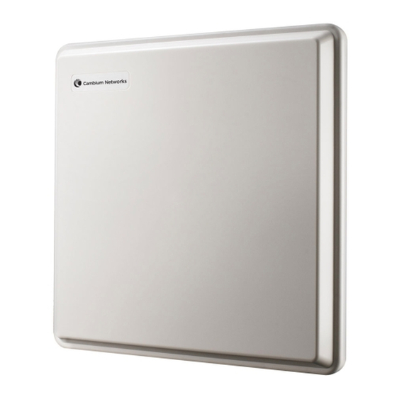
Page 49: Outdoor Unit (Odu)
Figure 1-2) or connectorized (without an antenna, Figure 1-3). Figure 1-2 PTP 600 Series integrated ODU (front and rear views) Figure 1-3 PTP 600 Series connectorized ODU (front and rear views) phn-0896_012v000 Jul 2010 4Gon www.4Gon.co.uk info@4gon.co.uk Tel: +44 (0)1245 808195 Fax: +44 (0)1245 808299... -
Page 50: Odu Interfaces
Outdoor unit (ODU) Chapter 1 Product description Connectorized variant The connectorized ODU is designed to provide the system integrator and installer with the ability to provide extra capability to cope with very difficult radio links compared to the integrated model. This allows the use of externally mounted antennas that have higher gains than provided by the integrated antenna. -
Page 51: Connectorized Odu Antenna Interfaces
User Guide: PTP 600 Series Outdoor unit (ODU) Connectorized ODU antenna interfaces The connectorized ODU also has interfaces to connect to an external antenna (Figure 1-5) via a cable of type LMR100, LMR200, LMR300, LMR400 or LMR600. The ‘V’ interface is for vertical polarization and the ‘H interface is for horizontal polarization. -
Page 52: Network Connection
Outdoor unit (ODU) Chapter 1 Product description Network connection The network connection to a PTP 600 Series is made via a 1000BaseT Ethernet connection. Power is provided to the ODU over the 1000BaseT Ethernet connection using a patented non-standard powering technique. -
Page 53: Powered Indoor Unit (Pidu Plus)
RJ45 connectors. Refer to Cabling and lightning protection on page 1-16. The ODU for the PTP 600 Series should only be deployed using the supplied PIDU Plus PTP 300/500/600 Series. CAUTION Care should be taken not to connect equipment other than an ODU, LPU or PTP-SYNC for the PTP 600 Series to a PIDU Plus ODU port, as equipment damage may occur. -
Page 54: Figure 1-8 Pidu Plus Power Input
Powered indoor unit (PIDU Plus) Chapter 1 Product description Table 1-3 PIDU Plus interfaces Interface Function 100-240V 47-63Hz 1.8A Mains power input (Figure 1-8). DC In Alternative DC power supply input. Refer to Redundancy and alternative powering configurations on page 1-13. DC Out DC power output to a second PIDU Plus. -
Page 55: Redundancy And Alternative Powering Configurations
User Guide: PTP 600 Series Powered indoor unit (PIDU Plus) Redundancy and alternative powering configurations The PTP 600 Series can be powered from an external DC source and can be provided with power supply redundancy as follows: • External DC supply only... -
Page 56: Figure 1-10 External Dc Supply Only
Powered indoor unit (PIDU Plus) Chapter 1 Product description Figure 1-10 External DC supply only Figure 1-11 External DC supply and AC supply Figure 1-12 External DC supply and redundant AC supply phn-0896_012v000 Jul 2010 1-14 4Gon www.4Gon.co.uk info@4gon.co.uk Tel: +44 (0)1245 808195 Fax: +44 (0)1245 808299... -
Page 57: Remote Leds And Recovery Switch
User Guide: PTP 600 Series Powered indoor unit (PIDU Plus) Remote LEDs and recovery switch The PIDU Plus provides a facility to connect remote LEDs and Recovery switch allowing the PIDU Plus to be mounted inside an enclosure. At the left hand end of the PIDU Plus under the ODU connection cover can be found a PCB header and three jumpers. -
Page 58: Cabling And Lightning Protection
The amount of lightning protection is dependent on regulatory requirements and the end user requirements. The standard ODU for the PTP 600 Series is fitted with surge limiting circuits and other features to minimize the risk of damage due to nearby lightning strikes. -
Page 59: Indoor Connections
User Guide: PTP 600 Series Cabling and lightning protection Indoor connections The CAT5e cable that connects the PIDU Plus to the network equipment must meet the screening requirements specified in Cable and connector specifications on page 4-16. CAUTION The connected network equipment must feature screened RJ45 connectors and must be connected to ground, otherwise the PIDU Plus will not be grounded. -
Page 60: Lightning Protection Units (Lpus)
Chapter 1 Product description Lightning protection units (LPUs) Separate Ethernet surge suppressors (lightning protection units) must be installed and grounded. Lightning protection units can be sourced from Motorola Point-to-Point distributors or solutions providers. LPU double end kit The LPU double end kit (Figure 1-15) is required for ODU drop cables. -
Page 61: Figure 1-16 Lpu Single End Kit
User Guide: PTP 600 Series Cabling and lightning protection LPU single end kit The LPU single end kit (Figure 1-16) is required for GPS drop cables, when GPS is the timing reference source for PTP-SYNC (optional). The LPU is installed near the building entry point. -
Page 62: Ptp-Sync Unit
PTP-SYNC unit Chapter 1 Product description PTP-SYNC unit PTP-SYNC unit description The PTP-SYNC unit (Figure 1-17) is an optional component. It is required when TDD synchronization is implemented using PTP-SYNC. It measures the difference between the TDD frame timing and a 1 Hz timing reference, and signals this time difference to the ODU. -
Page 63: Ptp-Sync Unit Interfaces
Function GPS/SYNC IN Input from GPS receiver module. SYNC OUT Output to daisy-chained PTP-SYNC units. Input for software upgrades. Contact Motorola for instructions. 1PPS IN Coaxial alternative to GPS/SYNC IN. Peak input voltage must not exceed 5 V. LED bank... -
Page 64: Ptp-Sync Maximum Cable Lengths
PTP-SYNC unit Chapter 1 Product description Table 1-6 PTP-SYNC indicator LEDs Indicator Function Description No GPS satellite data being received at the GPS/SYNC IN port. On steady or blink GPS satellite data being received. SYNC No data being received at the SYNC OUT port. -
Page 65: Wireless Operation
Wireless operation Time division duplexing TDD cycle PTP 600 series links operate using Time Division Duplexing (TDD). PTP 600 uses a TDD cycle in which the ODUs alternately transmit and receive TDD bursts. The TDD cycle is illustrated in Figure 1-19. -
Page 66: Figure 1-19 Tdd Cycle
Chapter 1 Product description Channel selection The PTP 600 series links are capable of transmitting and receiving on the same channel or on different channels. In other words, the slave-master direction may use a different channel from the master-slave direction. Independent selection of transmit and receive frequencies can be useful in planned networks or for countering interference. -
Page 67: Link Mode Optimization
2:1 The capacity in the direction Master to Slave is twice that of the direction Slave to Master. The PTP 600 series achieves this by setting the Burst Duration of the Master to twice that of the Slave. This mode is not available when TDD synchronization is enabled. -
Page 68: Ofdm And Channel Bandwidth
The PTP 600 series achieves this by increasing (or decreasing) the duration of the Transmit Burst in a given link direction as the offered level of network traffic increases (or decreases) in this same direction. -
Page 69: Spectrum Management
Spectrum management measurements The PTP 600 Series performs two mean signal measurements per TDD cycle, per channel. This mean measurement represents the mean received signal power for the 40 microseconds measurement period. -
Page 70: Adaptive Modulation
Adaptive modulation The PTP 600 series can transport data over the wireless link using a number of different modulation modes ranging from 256QAM 0.81 to BPSK 0.63. For a given channel bandwidth and TDD frame structure, each modulation mode transports data at a fixed rate. -
Page 71: Mimo
1-28. Intelligent dynamic frequency selection The PTP 600 series uses an interference mitigation technique known as Intelligent Dynamic Frequency Selection (i-DFS). Both the PTP 600 Master and PTP 600 Slave continually monitor for interference on all channels and then select the best frequency of operation. -
Page 72: Radar Avoidance
Wireless operation Chapter 1 Product description Radar avoidance Radar avoidance requires that equipment used in the region: • Detects interference from other systems and avoids co-channel operation with these systems, notably radar systems. • Provides a uniform loading of the spectrum across all devices, that is, fixed frequency operation is not allowed. -
Page 73: Security
Wireless operation Security The Motorola PTP 600 Series supports optional encryption for data transmitted over the wireless link. The encryption algorithm used is the Advanced Encryption Standard (AES) with 128-bit and 256-bit key size. AES is a symmetric encryption algorithm approved by U.S. -
Page 74: Ptp Networks
For help with planning networks, refer to Chapter 2 Planning considerations, or contact your Motorola distributor or re-seller. Synchronized networks TDD synchronization can be used to relax constraints on the frequency planning of PTP networks. Synchronization has the following benefits: •... -
Page 75: Tdd Synchronization
User Guide: PTP 600 Series Wireless operation Each synchronized unit is assigned to one of two phases. A master ODU can be assigned to either phase. A slave ODU must be assigned to a different phase from the associated master ODU. - Page 76 Wireless operation Chapter 1 Product description Timing references for use with PTP-SYNC PTP-SYNC requires an external timing reference in all but the simplest networks. Up to ten PTP-SYNCs can be connected in a chain to share the timing signal from one timing reference.
- Page 77 User Guide: PTP 600 Series Wireless operation Advantages of PTP-SYNC over UltraSync PTP-SYNC has several advantages over the UltraSync solution: • PTP-SYNC does not require individual GPS receivers, nor must they be located close to the ODUs. This reduces the complexity and the cost of the installation on the mast.
-
Page 78: Ethernet Bridging
Customer network Transparent Ethernet service The PTP 600 Series provides an Ethernet service between the Ethernet port at a local ODU and the Ethernet port at an associated remote ODU. The Ethernet service is based on conventional layer two transparent bridging, and is equivalent to the Ethernet Private Line (EPL) service defined by the Metro Ethernet Forum (MEF). -
Page 79: Management Network
Ethernet bridging Quality of service for bridged Ethernet traffic The PTP 600 Series supports eight traffic classes for Ethernet frames queued for transmission over the wireless link. Ethernet frames are classified by inspection of the Ethernet priority code point in the outermost VLAN tag. - Page 80 Ethernet bridging Chapter 1 Product description VLAN membership The management agent can be configured to transmit and receive either untagged, priority-tagged, C-tagged (IEEE 802.1Q) or S-tagged (IEEE 801.ad) frames. S-tagged frames must be single tagged, in other words, an S-tag with no encapsulated C-tag. The VLAN ID can be 0 (priority tagged) or in the range 1 to 4094.
-
Page 81: Back-To-Back Links
Wireless link down alert The PTP 600 Series provides an optional indication of failure of the wireless link by means of a brief disconnection of the Copper data port or the Fiber data port. The Wireless link down alert can be used to trigger protection switching by Spanning Tree Protocol (STP) or Ethernet Automatic Protection Switching (EAPS) in a redundant network. -
Page 82: Figure 1-20 Protocol Layers Between Ethernet And Wireless Interfaces
Ethernet bridging Chapter 1 Product description Figure 1-20 Protocol layers between Ethernet and wireless interfaces Ethernet Port Wireless Port Media Access Method MAC Relay Entity Independent Functions Media Access Method Dependent Convergence Functions PTP Medium Access Method PTP Security Media Access Method IEEE 802.3 (Optional) Specific Functions... -
Page 83: Telecoms Circuits
User Guide: PTP 600 Series Telecoms circuits Telecoms circuits The PTP 600 link provides native support for one or two E1 links, or one or two T1 links. The link relays unstructured E1 or T1 data and provides accurate timing transfer. -
Page 84: Further Reading
Telecoms circuits Chapter 1 Product description Further reading Installation details are provided in Installing an E1 or T1 interface on page 5-49. E1/T1 circuits are configured using the web pages described in Updating wireless configuration on page 6-50 Configuring telecoms circuits on page 6-68. -
Page 85: System Management
User Guide: PTP 600 Series System management System management Management agent PTP 600 equipment is managed through an embedded management agent. Management workstations, network management systems or PCs can be connected to this agent using standard management protocols multiplexed with user traffic at the Ethernet data port. - Page 86 System management Chapter 1 Product description The web-based management interfaces provide comprehensive web-based fault, configuration, performance and security management functions organized into the following web-pages and groups: • Home: The Home web-page reports Wireless Link Status and basic information needed to identify the link. The Home page additionally lists all active alarm conditions •...
-
Page 87: Password Complexity
User Guide: PTP 600 Series System management NOTE The PTP 600 has no default public key certificate, and Motorola is not able to generate private keys or public key certificates for specific network applications. User account management PTP 600 allows a network operator to configure a policy for login attempts, the period of validity of passwords and the action taken on expiry of passwords. -
Page 88: Radius Authentication
RFC-3415. SNMP-VIEW-BASED-ACM-MIB vacmMIBObjects group. • RFC-3418. SNMPv2-MIB. System group, SNMP group, and set group. • RFC-3826. SNMP-USM-AES-MIB. usmAesCfb128Protocol OID. • PTP 600 Series proprietary MIB phn-0896_012v000 Jul 2010 1-46 4Gon www.4Gon.co.uk info@4gon.co.uk Tel: +44 (0)1245 808195 Fax: +44 (0)1245 808299... -
Page 89: Snmpv3 Security
User Guide: PTP 600 Series System management SNMPv3 security SNMP Engine ID PTP 600 supports three different formats for SNMP Engine ID: • MAC address • IP address • Configurable text string SNMPv3 security configuration is re-initialized when the SNMP Engine ID is changed. - Page 90 System management Chapter 1 Product description Access to critical security parameters The SNMPv3 management interface does not provide access to critical security parameters (CSPs) of PTP 600. It is not possible to read or modify AES keys used to encrypt data transmitted at the wireless interface. Neither is it possible to read or modify security parameters associated with TLS protection of the web-based management interface.
- Page 91 User Guide: PTP 600 Series System management The default user is created with a view of the entire MIB, requiring initial authentication for SET operations. There is no access for template users. NOTE VACM grants access for requests sent with more than the configured security level.
- Page 92 System management Chapter 1 Product description Web-based security configuration is re-initialized when any of the following occurs: • All ODU configuration data is erased. • The SNMP Engine ID Format has been changed. • The SNMP Engine ID Format is IP Address and the IP Address has been changed. •...
-
Page 93: System Logging (Syslog)
User Guide: PTP 600 Series System management System logging (syslog) PTP 600 supports the standard syslog protocol to log important events. The protocol complies with RFC 3164. PTP 600 reports syslog event notification messages in the following families: • Local log •... -
Page 94: Aes License
PTP 600 provides optional encryption using the Advanced Encryption Standard (AES). Encryption is not available in the standard PTP 600 system. AES upgrades are supplied as an access key purchased from your Motorola Point-to- Point distributor or solutions provider. The access key authorizes AES operation for one ODU. -
Page 95: Critical Security Parameters
Zeroize CSPs option in Recovery mode. Capacity upgrades Capacity upgrades are supplied as an access key purchased from your Motorola Point- to-Point distributor or solutions provider. The upgrade is applied by entering an access key together with the MAC address of the target ODU into the PTP License Key Generator web page, which may be accessed from http://www.motorola.com/ptp/support. -
Page 96: Software Upgrade
SNMP interface. PTP 600 software images are digitally signed, and the ODU will accept only images that contain a valid Motorola PTP digital signature. The ODU always requires a reboot to complete a software upgrade. NOTE Obtain the application software and this user guide from the support website BEFORE warranty expires. - Page 97 User Guide: PTP 600 Series System management Recovery mode options Options in recovery mode are as follows: • Load new main application software. • Reset all configuration data to factory default. This option resets IP and Ethernet configuration, and erases (zeroizes) critical security parameters.
-
Page 98: Fips 140-2
The ODU will also have compatible hardware security if the part number suffix is earlier and PTP 600 Hardware Security Upgrade has been applied. The Hardware Security Upgrade Kit is available as Motorola part number WB3593AA. Units with compatible hardware security have tamper-evident labels fitted as shown in... -
Page 99: Figure 1-22 Tamper Evident Label On Side Edge Of Odu
User Guide: PTP 600 Series FIPS 140-2 Figure 1-22 Tamper evident label on side edge of ODU Figure 1-23 Tamper evident label on top edge of ODU The ODU will have hardware security compatible with FIPS 140-2 if the hardware version displayed on the Status page contains the string ‘FPS’, as shown in... -
Page 100: Fips 140-2 Mode
FIPS 140-2 Chapter 1 Product description Validated software image FIPS validated software images are indicated by a prefix to the file name, for FIPS- example: . The general features of a FIPS validated software FIPS-PTP600-09-01.DLD2 image are identical to those of the standard image with the same version number. For example, is equivalent to apart from the... -
Page 101: Figure 1-26 Fips Operational Mode Alarm
User Guide: PTP 600 Series FIPS 140-2 FIPS operational mode alarm The FIPS operational mode alarm indicates that the unit is FIPS 140-2 capable, but has not been configured correctly for FIPS 140-2 operation. The FIPS operational mode alarm appears as shown in Figure 1-26. - Page 102 FIPS 140-2 Chapter 1 Product description phn-0896_012v000 Jul 2010 1-60 4Gon www.4Gon.co.uk info@4gon.co.uk Tel: +44 (0)1245 808195 Fax: +44 (0)1245 808299...
-
Page 103: Chapter 2 Planning Considerations
Chapter 2 Chapter 2 Planning considerations ............This chapter provides information to help the user to plan a PTP 600 link. -
Page 104: Spectrum Planning
Spectrum planning Chapter 2 Planning considerations Spectrum planning Each frequency variant has specific licensing restrictions that affect frequency range, radar avoidance and channel bandwidth usage. Selecting a license for the region code Ensure the link is configured to conform to local regulatory requirements by installing License Keys for the correct region code. -
Page 105: Frequency Selection
User Guide: PTP 600 Series Spectrum planning Frequency selection Choose a method of frequency selection. The choice depends upon whether or not the region mandates radar detection. Regions without mandatory radar detection In regions that do not mandate DFS (Radar Detection), the frequencies may be configured symmetrically or asymmetrically (different transmit and receive frequencies). -
Page 106: Radar Avoidance
Spectrum planning Chapter 2 Planning considerations Radar avoidance Ensure that the link can operate without using any barred channels. Where regulatory restrictions apply to certain channels, these channels are barred. RTTT avoidance may be necessary in all channel bandwidths. The number of channels barred is dependant on the channel raster selected. -
Page 107: Variable Channel Bandwidth Operation
User Guide: PTP 600 Series Spectrum planning Variable channel bandwidth operation Select the Channel Bandwidth and Lower Center Frequency for the link. The selection of Channel Bandwidth depends upon the PTP 600 frequency variant: • For PTP 25600, PTP 45600, PTP 54600, PTP 58600 and PTP 59600, Channel Bandwidth may be 30, 15, 10 or 5 MHz. -
Page 108: Site Planning
Site planning Chapter 2 Planning considerations Site planning ODU site selection When selecting a site for the ODU, consider the following factors: • It should not be possible for people to stand or walk in front of the antenna. • Height and location to achieve the best radio path. -
Page 109: Ptp-Sync Site Selection
User Guide: PTP 600 Series Site planning PTP-SYNC site selection If PTP-SYNC is to be installed, consider the following factors when selecting a site: • Indoor location, or outdoor in a weatherproofed cabinet, with no possibility of condensation. • Accessibility for viewing status indicators. -
Page 110: Table 2-1 Lateral Force - Metric
Chapter 2 Planning considerations Calculation of lateral force The PTP 600 Series, with or without the integral antenna, is essentially a flat structure and so the magnitude of the lateral force can be estimated from: Force (in pounds) = 0.0042 . A . v Where A is the surface area in square feet and v is the wind speed in miles per hour. -
Page 111: Wind Speed Statistics
The structure and mounting brackets of the PTP 600 Series are capable of withstanding wind speeds up to 242 kph (151 mph). Ensure that the structure to which the PTP 600 Series is fixed to is also capable of withstanding the prevalent wind speeds and loads. -
Page 112: Link Planning
The PTP 600 Series will operate at ranges from 100 m (330 ft) to 200 km (124 miles), within 3 modes: 0-40km (0-25 miles), 0-100km (0-62 miles) and 0-200km (0-124 miles). -
Page 113: Using Ptp Link Planner For Synchronized Networks
User Guide: PTP 600 Series Link planning Using PTP Link Planner for synchronized networks TDD synchronization should be planned using Link Planner. This will provide the necessary TDD Frame parameter values which are required to complete a Link Planner User Guide synchronized installation. - Page 114 Link planning Chapter 2 Planning considerations For minimum error rates on TDM links, the maximum modulation mode should be limited to 64QAM 0.75. The values for (BPSK) are static receive sensitivity measurements. The other values are static receive sensitivity measurements with an AMOD threshold applied. The AMOD threshold applied is for a benign radio channel.
-
Page 115: When To Use The Connectorized Ptp 600 Antennas
Link planning When to use the connectorized PTP 600 antennas The majority of radio links can be successfully deployed with the PTP 600 Series. It should only be necessary to use external antennas where the Link Planner indicates marginal performance for a specific link, for example when the link is heavily obscured by dense woodland on an NLOS link or extremely long LOS links (>80km or >50... -
Page 116: Grounding And Lightning Protection
The actual degree of protection required depends on local conditions and applicable local regulations. Motorola recommends that PTP 600 installation is contracted to a professional installer. WARNING Electro-magnetic discharge (lightning) damage is not covered under warranty. -
Page 117: General Protection Requirements
NOTE Where an installation already has, or requires the use of a Master Ground R56: Standards And Bar then the requirements of Motorola specification Guidelines For Communication Sites (68P81089E50) take precedence over those in this guide. This specification is supplied on the PTP 600 CD-ROM. - Page 118 Grounding and lightning protection Chapter 2 Planning considerations Basic requirements The following basic protection requirements must be implemented: • The equipment (ODU or GPS receiver for PTP-SYNC) must be in ‘Zone B’ (see Lightning protection zones on page 2-14). • A lightning protection unit (LPU) must be installed within 600 mm (24 in) of the point at which the drop cable enters the building or equipment room.
-
Page 119: Protection Requirements For A Mast Or Tower Installation
User Guide: PTP 600 Series Grounding and lightning protection Figure 2-3 Grounding cable minimum bend radius and angle Radius not less than 203 mm (8 in) Angle not less than 90° ODU requirements The following ODU protection requirements must be implemented: •... -
Page 120: Figure 2-4 Grounding And Lightning Protection On Mast Or Tower
Grounding and lightning protection Chapter 2 Planning considerations • If the tower is greater than 61 m (200 ft in height, an additional grounding kit must be installed at the tower midpoint. Additional ground kits must be installed as necessary to reduce the distance between ground kits to 61 m (200 ft) or less. •... -
Page 121: Figure 2-5 Grounding And Lightning Protection On Mast Or Tower (With E1 Or T1)
User Guide: PTP 600 Series Grounding and lightning protection Figure 2-5 Grounding and lightning protection on mast or tower (with E1 or T1) phn-0896_012v000 Jul 2010 2-19 4Gon www.4Gon.co.uk info@4gon.co.uk Tel: +44 (0)1245 808195 Fax: +44 (0)1245 808299... -
Page 122: Protection Requirements For A Wall Installation
Grounding and lightning protection Chapter 2 Planning considerations Protection requirements for a wall installation If the ODU is to be mounted on the wall of a building, then in addition to the general protection requirements (above), the following requirements must be observed: •... -
Page 123: Figure 2-7 Grounding And Lightning Protection On Wall (With E1 Or T1)
User Guide: PTP 600 Series Grounding and lightning protection Figure 2-7 Grounding and lightning protection on wall (with E1 or T1) phn-0896_012v000 Jul 2010 2-21 4Gon www.4Gon.co.uk info@4gon.co.uk Tel: +44 (0)1245 808195 Fax: +44 (0)1245 808299... -
Page 124: Protection Requirements On A High Rise Building
Grounding and lightning protection Chapter 2 Planning considerations Protection requirements on a high rise building If the ODU is to be mounted on a high rise building, it is likely that cable entry is at roof level (Figure 2-8) and the equipment room is several floors below (Figure 2-9). -
Page 125: Figure 2-8 Grounding And Lightning Protection On Building
User Guide: PTP 600 Series Grounding and lightning protection Figure 2-8 Grounding and lightning protection on building phn-0896_012v000 Jul 2010 2-23 4Gon www.4Gon.co.uk info@4gon.co.uk Tel: +44 (0)1245 808195 Fax: +44 (0)1245 808299... -
Page 126: Figure 2-9 Grounding And Lightning Protection Inside High Building
Grounding and lightning protection Chapter 2 Planning considerations Protection inside a high rise building The following protection requirements must be observed inside multi-story or high rise buildings (Figure 2-9): • The drop cable shield must be bonded to the building grounding system at the entry point to the building. -
Page 127: Figure 2-10 Grounding In A High Rise Building - Building Steel Not Available
User Guide: PTP 600 Series Grounding and lightning protection Connecting to the grounding conductor Figure 2-10 Figure 2-11 illustrate the techniques employed to provide equipment grounding in high rise buildings. A steel component of the building can be used as a grounding conductor, provided it is part of the structural building steel and is effectively grounded. -
Page 128: Figure 2-11 Grounding In A High Rise Building - Building Steel Available
Grounding and lightning protection Chapter 2 Planning considerations Figure 2-11 Grounding in a high rise building – building steel available phn-0896_012v000 Jul 2010 2-26 4Gon www.4Gon.co.uk info@4gon.co.uk Tel: +44 (0)1245 808195 Fax: +44 (0)1245 808299... -
Page 129: Configuration Options For Tdd Synchronization
Configuration options for TDD synchronization Configuration options for TDD synchronization This section describes the different configuration options that may be used for implementing TDD synchronization in the PTP 600 Series. Schematic diagrams are included. TDD synchronization configurations supported The PTP 600 supports the following TDD synchronization configurations: •... -
Page 130: Single Link Configuration With Ultrasync
Configuration options for TDD synchronization Chapter 2 Planning considerations Single link configuration with UltraSync Each link requires an UltraSync GPS receiver, connected at the master ODU (Figure 2-12). The wireless configuration settings are: • Master Slave Mode = ‘Master’. • TDD Sync Device = ‘UltraSync’. -
Page 131: Single Link Configuration With Ptp-Sync
User Guide: PTP 600 Series Configuration options for TDD synchronization Single link configuration with PTP-SYNC Each link requires one PTP-SYNC unit connected to the master ODU and one compatible GPS receiver. Use this configuration where a site contains only one TDD master ODU. -
Page 132: Cluster With Ptp-Sync And Gps Receiver
Configuration options for TDD synchronization Chapter 2 Planning considerations Cluster with PTP-SYNC and GPS receiver Each link requires one PTP-SYNC unit. Each site requires one compatible GPS receiver. Collocated PTP-SYNC units are connected together in a daisy-chain. Between two and ten PTP-SYNCs may be chained in this way. Use this configuration where a site contains collocated TDD master ODUs in an extended network and where multiple sites have TDD master ODUs (Figure... -
Page 133: Cluster With Ptp-Sync And No Gps Receiver
User Guide: PTP 600 Series Configuration options for TDD synchronization Cluster with PTP-SYNC and no GPS receiver Each link requires one PTP-SYNC unit. PTP-SYNC units are connected together in a daisy-chain. Between two and ten PTP-SYNCs may be chained in this way. One ODU is designated as a cluster timing master. -
Page 134: Mounting Options For The Ptp-Sync Gps Receiver
Mounting options for the PTP-SYNC GPS receiver Chapter 2 Planning considerations Mounting options for the PTP-SYNC GPS receiver If PTP-SYNC is the selected TDD synchronization method, with a GPS receiver as the timing reference source, then the GPS receiver must be mounted as described in this section. -
Page 135: Mounting The Gps Receiver Module On The Equipment Building
User Guide: PTP 600 Series Mounting options for the PTP-SYNC GPS receiver Mounting the GPS receiver module on the equipment building If mounting the GPS receiver for PTP-SYNC on the equipment building (Figure 2-16), select a position on the wall that meets the following requirements: •... -
Page 136: Mounting The Gps Receiver Module On A Metal Tower Or Mast
Mounting options for the PTP-SYNC GPS receiver Chapter 2 Planning considerations Mounting the GPS receiver module on a metal tower or mast If mounting the GPS receiver module on a metal tower or mast (Figure 2-17), select a position that meets the following requirements: •... -
Page 137: Data Network Planning
User Guide: PTP 600 Series Data network planning Data network planning Management mode Decide how the PTP 600 will be managed. In the default in-band management mode, the management agent can be reached from the Ethernet port at the local ODU, and (assuming that the wireless link is established) from the Ethernet port at the remote ODU. -
Page 138: Ip Interface
Data network planning Chapter 2 Planning considerations IP interface Choose an IP address for the IP interface of the ODU management agent. The IP address must be unique and valid for the connected network segment and VLAN. Find out the correct subnet mask and gateway IP address for this network segment and VLAN. -
Page 139: Security Planning
User Guide: PTP 600 Series Security planning Security planning Planning for HTTPS/TLS operation Before starting to configure HTTPS/TLS operation, ensure that the cryptographic material listed in Table 2-3 is available. Table 2-3 HTTPS/TLS security material Item Description Quantity required Key of Keys An encryption key generated using a Two per link. -
Page 140: Planning For Fips 140-2 Operation
Security planning Chapter 2 Planning considerations Item Description Quantity required Wireless An encryption key generated using a One per link. The Link cryptographic key generator. The key same encryption key Encryption length is dictated by the selected AES is required at each Key for AES encryption algorithm (128 or 256 bits). -
Page 141: Planning For Snmp Operation
User Guide: PTP 600 Series Security planning CAUTION Configure all of the above correctly to ensure that PTP 600 is operating in compliance with the FIPS 140-2 validation. Planning for SNMP operation Supported notifications The supported notifications are as follows: •... - Page 142 Security planning Chapter 2 Planning considerations Supported alarms PTP 600 supports the following diagnostic alarms: • Region Code • Install Status • Install Arm State • Unit Out Of Calibration • Incompatible Region Codes • Incompatible Master And Slave • Ethernet Configuration Mismatch •...
-
Page 143: Planning For Snmpv3 Operation
User Guide: PTP 600 Series Security planning Enabling SNMP Enable the SNMP interface for use by configuring the following attributes in the Remote Management page: • SNMP State (default disabled) • SNMP Version (default SNMPv1/2c) • SNMP Port Number (default 161) - Page 144 Security planning Chapter 2 Planning considerations Web-based management of SNMPv3 security Initial configuration of SNMPv3 security is available only to HTTP or HTTPS/TLS user accounts with security role of Security Officer. Identify the minimum security role of HTTP or HTTPS/TLS user accounts that will be permitted access for web-based management of SNMPv3 security.
-
Page 145: Table 2-4 Permitted Character Set For Snmpv3 Passphrases
User Guide: PTP 600 Series Security planning AES link encryption is only available to users who have purchased an appropriate license key. If authentication or authentication and privacy protocols are required, identify passphrases for each protocol for each SNMP user. It is considered good practice to use different passphrases for authentication and privacy. - Page 146 Security planning Chapter 2 Planning considerations phn-0896_012v000 Jul 2010 2-44 4Gon www.4Gon.co.uk info@4gon.co.uk Tel: +44 (0)1245 808195 Fax: +44 (0)1245 808299...
-
Page 147: Chapter 3 Legal Information
Any such modifications could void the user’s authority to operate the equipment and will void the manufacturer’s warranty. The following topics are described in this chapter: • Motorola Inc. end user license agreement on page • Hardware warranty on page 3-23 •... -
Page 148: Motorola Inc. End User License Agreement
The word “Documentation” refers to electronic or printed manuals and accompanying instructional aids licensed to you. The word “Product” refers to Motorola’s MOTOwi4™ fixed wireless broadband devices for which the Software and Documentation is licensed for use. -
Page 149: Conditions Of Use
If the Documentation is in electronic form, you may print out 1 copy, which then may not be copied. With regard to the copy made for backup or archival purposes, you agree to reproduce any Motorola copyright notice, and other proprietary legends appearing thereon. Such copyright... -
Page 150: Title And Restrictions
Title and copyrights to the Software and Documentation and any copies made by you remain with Motorola and its licensors. You will not, and will not permit others to: (i) modify, translate, decompile, bootleg, reverse engineer, disassemble, or extract the inner workings of the Software or Documentation, (ii) copy the look-and-feel or functionality of the Software or Documentation;... -
Page 151: Right To Use Motorola's Name
Except as required in “Conditions of use”, you will not, during the term of this Agreement or thereafter, use any trademark of Motorola, or any word or symbol likely to be confused with any Motorola trademark, either alone or in any combination with another word or words. -
Page 152: Disclaimer
THE TOTAL LIABILITY OF MOTOROLA UNDER THIS AGREEMENT FOR DAMAGES WILL NOT EXCEED THE TOTAL AMOUNT PAID BY YOU FOR THE PRODUCT LICENSED UNDER THIS AGREEMENT. IN NO EVENT WILL MOTOROLA BE LIABLE IN ANY WAY FOR INCIDENTAL, CONSEQUENTIAL, INDIRECT, SPECIAL OR... -
Page 153: U.s. Government
Agreement by you. Within 30 days after termination of this Agreement, you will certify to Motorola in writing that through your best efforts, and to the best of your knowledge, the original and all copies, in whole or in part, in any form, of the... -
Page 154: Survival Of Provisions
This agreement contains the parties’ entire agreement regarding your use of the Software and may be amended only in writing signed by both parties, except that Motorola may modify this Agreement as necessary to comply with applicable laws. Third party software The software may contain one or more items of Third-Party Software supplied by other third-party suppliers. - Page 155 User Guide: PTP 600 Series Motorola Inc. end user license agreement notice appears in all copies and that both that copyright notice and this permission notice appear in supporting documentation, and that the name of CMU and The Regents of the University of California not be used in advertising or publicity pertaining to distribution of the software without specific written permission.
- Page 156 Motorola Inc. end user license agreement Chapter 3 Legal information ---- Part 3: Cambridge Broadband Ltd. copyright notice (BSD) ----- Portions of this code are copyright © 2001-2003, Cambridge Broadband Ltd. All rights reserved. Redistribution and use in source and binary forms, with or without modification, are permitted provided that the following conditions are met: •...
- Page 157 User Guide: PTP 600 Series Motorola Inc. end user license agreement • Redistributions in binary form must reproduce the above copyright notice, this list of conditions and the following disclaimer in the documentation and/or other materials provided with the distribution.
- Page 158 Motorola Inc. end user license agreement Chapter 3 Legal information PROCUREMENT OF SUBSTITUTE GOODS OR SERVICES; LOSS OF USE, DATA, OR PROFITS; OR BUSINESS INTERRUPTION) HOWEVER CAUSED AND ON ANY THEORY OF LIABILITY, WHETHER IN CONTRACT, STRICT LIABILITY, OR TORT...
- Page 159 User Guide: PTP 600 Series Motorola Inc. end user license agreement Author: Bernhard Penz Redistribution and use in source and binary forms, with or without modification, are permitted provided that the following conditions are met: • Redistributions of source code must retain the above copyright notice, this list of conditions and the following disclaimer.
- Page 160 Motorola Inc. end user license agreement Chapter 3 Legal information 4. The names “OpenSSL Toolkit” and “OpenSSL Project” must not be used to endorse or promote products derived from this software without prior written permission. For written permission, please contact openssl-core@openssl.org.
- Page 161 User Guide: PTP 600 Series Motorola Inc. end user license agreement If this package is used in a product, Eric Young should be given attribution as the author of the parts of the library used. This can be in the form of a textual message at program startup or in documentation (online or textual) provided with the package.
- Page 162 Motorola Inc. end user license agreement Chapter 3 Legal information Zlib Copyright © 1995-2005 Jean-loup Gailly and Mark Adler This software is provided ‘as-is’, without any express or implied warranty. In no event will the authors be held liable for any damages arising from the use of this software.
- Page 163 User Guide: PTP 600 Series Motorola Inc. end user license agreement particular purposes or needs. This library is provided with all faults, and the entire risk of satisfactory quality, performance, accuracy, and effort is with the user. libpng versions 0.97, January 1998, through 1.0.6, March 20, 2000, are Copyright ©...
- Page 164 Motorola Inc. end user license agreement Chapter 3 Legal information Permission is hereby granted to use, copy, modify, and distribute this source code, or portions hereof, for any purpose, without fee, subject to the following restrictions: 1. The origin of this source code must not be misrepresented.
- Page 165 User Guide: PTP 600 Series Motorola Inc. end user license agreement 4. The name of the author may not be used to endorse or promote products derived from this software without specific prior written permission. THIS SOFTWARE IS PROVIDED BY THE AUTHOR “AS IS” AND ANY EXPRESS OR...
- Page 166 Motorola Inc. end user license agreement Chapter 3 Legal information Foundation, Inc. and its contributors. 4. Neither the name of The NetBSD Foundation nor the names of its contributors may be used to endorse or promote products derived from this software without specific prior written permission.
- Page 167 User Guide: PTP 600 Series Motorola Inc. end user license agreement ------------------------------------------------------------------------------ Copyright (C) 1995,1996,1997,1998 Lars Fenneberg <lf@elemental.net> Permission to use, copy, modify, and distribute this software for any purpose and without fee is hereby granted, provided that this copyright and permission notice...
- Page 168 Motorola Inc. end user license agreement Chapter 3 Legal information THIS SOFTWARE IS PROVIDED "AS IS" WITHOUT WARRANTY OF ANY KIND, EITHER EXPRESS OR IMPLIED, INCLUDING WITHOUT LIMITATION WARRANTIES OF MERCHANTABILITY AND FITNESS FOR A PARTICULAR PURPOSE. THE REGENTS OF THE UNIVERSITY OF MICHIGAN AND MERIT NETWORK, INC. DO...
-
Page 169: Hardware Warranty
Hardware warranty Hardware warranty Motorola’s standard hardware warranty is for one (1) year from date of shipment from Motorola or a Motorola Point-to-Point Distributor. Motorola warrants that hardware will conform to the relevant published specifications and will be free from material defects in material and workmanship under normal use and service. -
Page 170: Limit Of Liability
Chapter 3 Legal information Limit of liability IN NO EVENT SHALL MOTOROLA BE LIABLE TO YOU OR ANY OTHER PARTY FOR ANY DIRECT, INDIRECT, GENERAL, SPECIAL, INCIDENTAL, CONSEQUENTIAL, EXEMPLARY OR OTHER DAMAGE ARISING OUT OF THE USE OR INABILITY TO... - Page 171 Chapter 4 Chapter 4 Reference information ............This chapter describes the reference information and regulatory notices that are common to all PTP 600 products and those that are specific to each frequency variant.
-
Page 172: Chapter 4 Reference Information
600 bridge installations and for the main installation options, such as connectorized ODUs, PTP-SYNC, GPS and E1 or T1. Inventory for standard installations A standard PTP 600 Series bridge installation requires the components listed in Table 4-1. Table 4-1 Standard PTP 600 Series bridge components... - Page 173 User Guide: PTP 600 Series Installation inventories Item Notes Outdoor drop cable Purchase separately. CAUTION Always use Cat5e cable that is gel-filled and shielded with copper-plated steel. Alternative types of drop cable are not supported by Motorola. Refer to Cable and connector specifications on page 4-16.
- Page 174 Installation inventories Chapter 4 Reference information Item Notes Lightning Protection Unit (LPU) double end Motorola part number WB2907C. Two kits required per standard link (total four LPUs). Kit contents: two LPUs, grounding cables, 600mm ODU to LPU cable, nuts, bolts and glands.
-
Page 175: Inventory For Connectorized Bridge Installations
User Guide: PTP 600 Series Installation inventories Inventory for connectorized bridge installations A connectorized PTP 600 Series bridge installation requires all of the standard installation components (apart from the integrated ODU). It also requires the components listed in Table 4-2. - Page 176 Installation inventories Chapter 4 Reference information Item Notes RF cable connectors Purchase separately. N type male connectors are required for connecting the RF cable to the ODU. For the antenna end of the RF cable, refer to the antenna manufacturer’s instructions.
-
Page 177: Inventory For Ultrasync Installations
User Guide: PTP 600 Series Installation inventories Inventory for UltraSync installations A PTP 600 Series bridge installation with UltraSync GPS requires all of the standard installation components (Table 4-1), with the addition of one MemoryLink UltraSync GPS-100M kit (Motorola part number WB3001) (Figure 4-1). -
Page 178: Inventory For Ptp-Sync Installations
Table 4-3 PTP-SYNC installation components Item Notes PTP-SYNC kit Motorola part number WB3665. Kit contents: 1 x PTP-SYNC unit 1 x M4 pan screw 2 x M4 washers 2 x M3 (6mm) torx drive screws... -
Page 179: Inventory For Gps Receiver Installations
User Guide: PTP 600 Series Installation inventories Item Notes PTP800 CMU / PTP-SYNC 19” rack Motorola part number WB3486. mount installation kit Required for rack-mounted PTP-SYNC units. Kit contents: 1 x rack bracket 8 x M3 washers 8 x M3 screws... - Page 180 Trimble GPS receiver. Refer to Outdoor connectors and glands – Trimble GPS page 4-17. Cable grounding kits for 1/4” and 3/8” Motorola part number 01010419001. cable One per drop cable grounding point. Kit contents: grounding cable, self- amalgamating tape, PVC tape, tie-wraps, bolts, washers and nuts.
-
Page 181: Inventory For E1 Or T1 Installations
User Guide: PTP 600 Series Installation inventories Inventory for E1 or T1 installations A PTP 600 Series bridge installation with E1 or T1 requires all of the standard installation components (Table 4-1), with the following additions: • Extra outdoor drop cable is required for the E1 or T1 link. -
Page 182: Odu Specifications
Chapter 4 Reference information ODU specifications This section contains specifications of the outdoor unit (ODU) that is supplied by Motorola for PTP 600 installations. These specifications apply to all PTP 600 product variants. Dimensions and weight The PTP 600 integrated ODU conforms to the physical specifications listed in Table 4-5. -
Page 183: Environmental
User Guide: PTP 600 Series ODU specifications Environmental The PTP 600 ODU conforms to the environmental specifications listed in Table 4-10. Table 4-7 ODU environmental specifications Category Specification Temperature -40°C (40°F) to +60°C (140°F) Wind loading 150 mph (242 kph) maximum. See... -
Page 184: Pidu Plus Specifications
Chapter 4 Reference information PIDU Plus specifications This section contains specifications of the powered indoor unit (PIDU Plus) that is supplied by Motorola for PTP 600 installations. These specifications apply to all PTP 600 product variants. Dimensions and weight The PTP 600 PIDU Plus conforms to the physical specifications listed in Table 4-8. -
Page 185: Electrical
User Guide: PTP 600 Series PIDU Plus specifications Electrical The PTP 600 PIDU Plus conforms to the electrical specifications listed in Table 4-10. Table 4-10 PIDU Plus electrical specifications Category Specification AC Input 90 – 264 V AC, 47 – 60 Hz Alternative DC Input 36 –... -
Page 186: Cable And Connector Specifications
CAUTION Always use Cat5e cable that is gel-filled and shielded with copper-plated steel. Alternative types of drop cable are not supported by Motorola. A suitable make of outdoor drop cable is Superior Essex BBDGe, with part numbers as specified in Table 4-11. -
Page 187: Outdoor Connectors And Glands - Trimble Gps
User Guide: PTP 600 Series Cable and connector specifications NOTE The connector, crimp tool and die set listed in Table 4-12 are specific to Superior Essex BBDGe cable. They may not work with other makes of cable. Outdoor connectors and glands – Trimble GPS... -
Page 188: Antenna Specifications
However, the Maximum Transmit Power must be reduced to avoid exceeding the EIRP limits. In FCC regions when using external antennas, cable loss between the connectorized version of the PTP 600 Series and the antenna ports must not be less than 1.2 dB. phn-0896_012v000 Jul 2010 4-18 4Gon www.4Gon.co.uk info@4gon.co.uk Tel: +44 (0)1245 808195 Fax: +44 (0)1245 808299... -
Page 189: Table 4-14 Allowed Antennas For Deployment In Usa/Canada - 5.4 Ghz
User Guide: PTP 600 Series Antenna specifications CAUTION Antennas not included in this table, or those having a gain greater than the specified maximum, are strictly prohibited for use with the PTP 54600. The required antenna impedance is 50 ohms. - Page 190 Antenna specifications Chapter 4 Reference information Manufacturer Antenna Type Gain Parabolic (dBi) Dish Gabriel Gabriel 4-foot Standard QuickFire Parabolic, 34.8 QF4-52-N-RK Gabriel Gabriel 2-foot Standard Dual QuickFire 28.4 Parabolic, QFD2-52-N Gabriel Gabriel 2.5-foot Standard Dual QuickFire 31.1 Parabolic, QFD2.5-52-N Gabriel Gabriel 2-foot Standard Dual QuickFire 28.4 Parabolic, QFD2-52-N-RK...
-
Page 191: Ptp 58600 Fcc Antenna Restrictions
Polarization Parabolic Dish Antennas: up to 37.7 dBi per polarization or antenna. In FCC regions when using external antennas, cable loss between the connectorized version of the PTP 600 Series and the antenna ports must not be less than 1.2 dB. CAUTION Antennas not included in this table, or those having a gain greater than the specified maximum, are strictly prohibited for use with the PTP 58600. - Page 192 Antenna specifications Chapter 4 Reference information Manufacturer Antenna Type Gain Flat Parabolic (dBi) Plate Dish Gabriel Gabriel 2-foot Flat Panel, DFPD2-52 (28dBi) MTI 17 inch Diamond Flat Panel, MT- 485009 (23dBi) MTI 15 inch Dual-Pol Flat Panel, MT-485025/NVH (23dBi) MTI 2 ft Directional Flat Panel, MT- 20004 (28dBi) MTI 2 ft Flat Panel, MT-486001 (28dBi) RFS 1-foot Flat Panel, MA0528-23AN...
- Page 193 User Guide: PTP 600 Series Antenna specifications Manufacturer Antenna Type Gain Flat Parabolic (dBi) Plate Dish Gabriel Gabriel 2-foot High Performance 28.2 QuickFire Parabolic, HQF2-52-N Gabriel Gabriel 4-foot High Performance 34.4 QuickFire Parabolic, HQF4-52-N Gabriel Gabriel 6-foot High Performance 37.4...
- Page 194 Antenna specifications Chapter 4 Reference information Manufacturer Antenna Type Gain Flat Parabolic (dBi) Plate Dish Gabriel Gabriel 2-foot Standard Dual QuickFire 28.4 Parabolic, QFD2-52-N-RK Gabriel Gabriel 4-foot Standard Dual QuickFire 34.7 Parabolic, QFD4-52-N Gabriel Gabriel 4-foot Standard Dual QuickFire 34.7 Parabolic, QFD4-52-N-RK Gabriel Gabriel 6-foot Standard Dual QuickFire...
-
Page 195: Table 4-16 Sectored Antennas For Deployment In Usa/Canada - 5.8 Ghz
User Guide: PTP 600 Series Antenna specifications Manufacturer Antenna Type Gain Flat Parabolic (dBi) Plate Dish RFS 2-foot Parabolic, SPF2-52AN or 27.9 SPFX2-52AN (27.9dBi) RFS 3-foot Parabolic, SPF3-52AN or 31.4 SPFX3-52AN(31.4dBi) RFS 4-foot Parabolic, SPF4-52AN or 33.9 SPFX4-52AN(33.9dBi) RFS 6-foot Parabolic, SPF6-52AN or 37.4... -
Page 196: Ptp-Sync Specifications
PTP-SYNC specifications Chapter 4 Reference information PTP-SYNC specifications This section contains specifications of the PTP-SYNC unit that is supplied by Motorola for PTP 600 installations that require TDD synchronization via PTP-SYNC (optional). Dimensions and weight The PTP-SYNC unit conforms to the physical specifications listed in Table 4-17. -
Page 197: Electrical
User Guide: PTP 600 Series PTP-SYNC specifications Electrical The PTP-SYNC unit conforms to the electrical specifications listed in Table 4-19. Table 4-19 PTP-SYNC unit electrical specifications Category Specification Power source 90 – 264 V AC, 50 – 60 Hz, or 36 – 60 V DC... -
Page 198: Gps/Sync In Pinout Description
PTP-SYNC specifications Chapter 4 Reference information Table 4-21 PTP-SYNC unit timing specifications - 1PPS IN (SMA) Category Specification Signal type 1 Hz signal Pulse Positive pulse, reference edge is rising edge Maximum voltage Threshold 0.4 V to 0.6 V Input impedance 45 ohms to 55 ohms Pulse width 1μs to 500ms... -
Page 199: Wireless Specifications
User Guide: PTP 600 Series Wireless specifications Wireless specifications General wireless specifications Table 4-23 PTP 25600 RF specifications Radio Technology Specification RF Band Lower: 2.496-2.568 GHz Middle: 2.572-2.614 GHz Upper: 2.618-2.690 GHz Channel Selection Manual selection. Dynamic Frequency Control Channel size... -
Page 200: Table 4-24 Ptp 45600 Rf Specifications
Wireless specifications Chapter 4 Reference information Table 4-24 PTP 45600 RF specifications Radio Technology Specification RF Band 4.400-4.600 GHz Channel Selection Manual selection. Dynamic Frequency By intelligent Dynamic Frequency Selection (i-DFS) or manual Control intervention; automatic selection on start-up and continual adaptation to avoid interference. -
Page 201: Table 4-25 Ptp 48600 Rf Specifications
User Guide: PTP 600 Series Wireless specifications Table 4-25 PTP 48600 RF specifications Radio Technology Specification RF Band 4.710-5.000 GHz Channel Selection Manual selection. Dynamic Frequency Control By intelligent Dynamic Frequency Selection (i-DFS) or manual intervention; automatic selection on start-up and continual adaptation to avoid interference. -
Page 202: Table 4-26 Ptp 49600 Rf Specifications
Wireless specifications Chapter 4 Reference information Table 4-26 PTP 49600 RF specifications Radio Technology Specification RF Band 4.900-4.990 GHz Channel Selection Manual selection. Dynamic Frequency Control By intelligent Dynamic Frequency Selection (i-DFS) or manual intervention; automatic selection on start-up and continual adaptation to avoid interference. -
Page 203: Table 4-27 Ptp 54600 Rf Specifications
User Guide: PTP 600 Series Wireless specifications Table 4-27 PTP 54600 RF specifications Radio Technology Specification RF Band 5.470-5.725 GHz Channel Selection By dynamic frequency control and manual intervention Automatic detection on start-up and continual adaptation to avoid interference. Dynamic Frequency Control Initial capture 10-15 sec. -
Page 204: Table 4-28 Ptp 58600 Rf Specifications
Wireless specifications Chapter 4 Reference information Table 4-28 PTP 58600 RF specifications Radio Technology Specification RF Band 5.725-5.850 GHz Channel Selection By dynamic frequency control and manual intervention Automatic detection on start-up and continual adaptation to avoid interference. Dynamic Frequency Control Initial capture 10-15 sec. -
Page 205: Table 4-29 Ptp 59600 Rf Specifications
User Guide: PTP 600 Series Wireless specifications Table 4-29 PTP 59600 RF specifications Radio Technology Specification RF Band 5.825-5.925GHz Channel Selection By dynamic frequency control and manual intervention Automatic detection on start-up and continual adaptation to avoid interference. Dynamic Frequency Control Initial capture 10-15 sec. -
Page 206: Licenses And Region Codes
Wireless specifications Chapter 4 Reference information Licenses and region codes This section specifies the licenses and region codes that are available for each frequency variant. When shipped, PTP 600 units are configured with a license key for a default region code, as indicated by (*1) in the following tables. -
Page 207: Table 4-31 Ptp 45600 Licenses And Region Codes
User Guide: PTP 600 Series Wireless specifications Table 4-31 PTP 45600 licenses and region codes Region License / Frequencies Channel Max Power Code Regulation Bandwidth US Federal 4400 - 4600 5, 10, 15, 20, 30 27 dBm (*1) NTIA 4400 - 4600... -
Page 208: Table 4-33 Ptp 49600 Licenses And Region Codes
Wireless specifications Chapter 4 Reference information Table 4-33 PTP 49600 licenses and region codes Region License / Frequencies Channel Max Power Notes code Regulation Bandwidth USA/Canada 4940 - 4990 5, 10, 20 MHz 24 dBm Public Safety note (*1) below. Hong Kong 4900 - 4950 5, 10, 20 MHz... -
Page 209: Table 4-34 Ptp 54600 Licenses And Region Codes
User Guide: PTP 600 Series Wireless specifications Table 4-34 PTP 54600 licenses and region codes Region License or Channel code Regulation Frequencies Bandwidth Power Notes Full Power + 5470 - 5725 5, 10, 15, 30 25 dBm Radar Full Power... -
Page 210: Table 4-35 Ptp 58600 Licenses And Region Codes
Wireless specifications Chapter 4 Reference information Region License or Channel code Regulation Frequencies Bandwidth Power Notes ETSI 5470 - 5600 30 MHz 30 dBm The band EIRP 5600 MHz (*1) 5650 - 5725 to 5650 MHz is 15 MHz 27 dBm reserved EIRP for the use... - Page 211 User Guide: PTP 600 Series Wireless specifications Region License / Frequencies Channel Notes code Regulation Bandwidth Power for Road 10 MHz 32 dBm Transport EIRP 5 MHz 29 dBm Traffic EIRP Telematic s (RTTT). Singapore 5725 - 5850 5, 10, 15, 30...
- Page 212 Wireless specifications Chapter 4 Reference information Region License / Frequencies Channel Notes code Regulation Bandwidth Power 5 MHz 37 dBm EIRP India 5825 - 5850 10, 15 MHz 36 dBm EIRP 5 MHz 33 dBm EIRP Thailand 5725 - 5850 5, 10, 15, 30 30 dBm EIRP...
-
Page 213: Table 4-36 Ptp 59600 Licenses And Region Codes
User Guide: PTP 600 Series Wireless specifications Region License / Frequencies Channel Notes code Regulation Bandwidth Power Denmark 5725 - 5795 30 MHz 35 dBm 5795 MHz 5815 - 5850 EIRP to 5815 MHz is 15 MHz 34 dBm assigned... -
Page 214: Available Spectrum Settings
Wireless specifications Chapter 4 Reference information Available spectrum settings PTP 25600 available spectrum settings The supported 2.5GHz frequency range is split into three bands, according to the bands specified in the FCC BRS-EBS Post-Transition Band plan (only for PTP 25600 and region code 16): •... -
Page 215: Figure 4-2 Ptp 25600 Brs Band Channel Assignments
User Guide: PTP 600 Series Wireless specifications Block Channel Channel Centre Frequencies (MHz) Bandwidth (MHz) Segment 2629.5, 2635, 2640.5, 2646, 2651.5, 2657, 2662.5, 2668, 2673.5, 2679, 2684.5 2632.25, 2637.75, 2643.25, 2648.75, 2654.25, 2659.75, 2665.25, 2670.75, 2676.25, 2681.75 2640.5, 2651.5, 2662.5, 2673.5... -
Page 216: Figure 4-3 Ptp 45600 Available Spectrum In 30 Mhz Channel Bandwidth (Rc 23)
Wireless specifications Chapter 4 Reference information PTP 45600 available spectrum settings The PTP 45600 product variant does not apply any band edge power reduction. Region code 23 Adjustment of the lower centre frequency allows the operator to slide the available frequency settings up and down the 4.5 GHz band in steps of 2 MHz. -
Page 217: Figure 4-4 Ptp 45600 Available Spectrum In 20 Mhz Channel Bandwidth (Rc 23)
User Guide: PTP 600 Series Wireless specifications Figure 4-4 PTP 45600 available spectrum in 20 MHz channel bandwidth (RC 23) Figure 4-5 PTP 45600 available spectrum in 15 MHz channel bandwidth (RC 23) phn-0896_012v000 Jul 2010 4-47 4Gon www.4Gon.co.uk info@4gon.co.uk Tel: +44 (0)1245 808195 Fax: +44 (0)1245 808299... -
Page 218: Figure 4-6 Ptp 45600 Available Spectrum In 10 Mhz Channel Bandwidth (Rc 23)
Wireless specifications Chapter 4 Reference information Figure 4-6 PTP 45600 available spectrum in 10 MHz channel bandwidth (RC 23) Figure 4-7 PTP 45600 available spectrum in 5 MHz channel bandwidth (RC 23) phn-0896_012v000 Jul 2010 4-48 4Gon www.4Gon.co.uk info@4gon.co.uk Tel: +44 (0)1245 808195 Fax: +44 (0)1245 808299... -
Page 219: Figure 4-8 Ptp 45600 Available Spectrum In 20 Mhz Channel Bandwidth (Rc 24)
User Guide: PTP 600 Series Wireless specifications Region code 24 (NTIA) In the 20 MHz (Figure 4-8) channel bandwidth, the PTP 45600 variant operates on a 20 MHz channel raster. In the 10 MHz (Figure 4-9) channel bandwidth, the PTP 45600 variant operates on a 10 MHz channel raster. -
Page 220: Figure 4-10 Ptp 48600 Available Spectrum In 20 Mhz Channel Bandwidth (Rc 15 And 23)
Wireless specifications Chapter 4 Reference information Figure 4-10 PTP 48600 available spectrum in 20 MHz channel bandwidth (RC 15 and Figure 4-11 PTP 48600 available spectrum in 15 MHz channel bandwidth (RC 15 and phn-0896_012v000 Jul 2010 4-50 4Gon www.4Gon.co.uk info@4gon.co.uk Tel: +44 (0)1245 808195 Fax: +44 (0)1245 808299... -
Page 221: Figure 4-12 Ptp 48600 Available Spectrum In The 10 Mhz Channel Bandwidth (Rc 15 And 23)
User Guide: PTP 600 Series Wireless specifications Figure 4-12 PTP 48600 available spectrum in the 10 MHz channel bandwidth (RC 15 and 23) Figure 4-13 PTP 48600 available spectrum in 5 MHz channel bandwidth (RC 15 and phn-0896_012v000 Jul 2010 4-51 4Gon www.4Gon.co.uk info@4gon.co.uk Tel: +44 (0)1245 808195 Fax: +44 (0)1245 808299... -
Page 222: Figure 4-14 Ptp 48600 Available Spectrum In The 20 Mhz Channel Bandwidth (Rc 24)
Wireless specifications Chapter 4 Reference information Region code 24 (NTIA) In the 20 MHz (Figure 4-14) channel bandwidth, the PTP 48600 variant operates on a 20 MHz channel raster. In the 10 MHz (Figure 4-15) channel bandwidth, the PTP 48600 variant operates on a 10 MHz channel raster. The channel raster is set to even centre frequencies. -
Page 223: Figure 4-17 Ptp 49600 Available Spectrum In The 10 Mhz Channel Bandwidth
User Guide: PTP 600 Series Wireless specifications Figure 4-17 PTP 49600 available spectrum in the 10 MHz channel bandwidth Figure 4-18 PTP 49600 available spectrum in the 5 MHz channel bandwidth PTP 54600 available spectrum settings Adjustment of the lower centre frequency allows the operator to slide the available frequency settings up and down the 5.4 GHz band in steps of 2 MHz. -
Page 224: Figure 4-19 Ptp 54600 Available Spectrum In 30 Mhz Channel Bandwidth
Wireless specifications Chapter 4 Reference information Figure 4-19 PTP 54600 available spectrum in 30 MHz channel bandwidth Figure 4-20 PTP 54600 available spectrum in 15 MHz channel bandwidth phn-0896_012v000 Jul 2010 4-54 4Gon www.4Gon.co.uk info@4gon.co.uk Tel: +44 (0)1245 808195 Fax: +44 (0)1245 808299... -
Page 225: Figure 4-21 Ptp 54600 Available Spectrum In 10 Mhz Channel Bandwidth
User Guide: PTP 600 Series Wireless specifications Figure 4-21 PTP 54600 available spectrum in 10 MHz channel bandwidth Figure 4-22 PTP 54600 available spectrum in 5 MHz channel bandwidth PTP 58600 available spectrum settings Adjustment of the lower centre frequency allows the operator to slide the available frequency settings up and down the 5.8 GHz band in steps of 2 MHz. -
Page 226: Figure 4-23 Ptp 58600 Available Spectrum In 30 Mhz Channel Bandwidth
Wireless specifications Chapter 4 Reference information Figure 4-23 PTP 58600 available spectrum in 30 MHz channel bandwidth Figure 4-24 PTP 58600 available spectrum in 15 MHz channel bandwidth phn-0896_012v000 Jul 2010 4-56 4Gon www.4Gon.co.uk info@4gon.co.uk Tel: +44 (0)1245 808195 Fax: +44 (0)1245 808299... -
Page 227: Figure 4-25 Ptp 58600 Available Spectrum In The 10 Mhz Channel Bandwidth
User Guide: PTP 600 Series Wireless specifications Figure 4-25 PTP 58600 available spectrum in the 10 MHz channel bandwidth Figure 4-26 PTP 58600 available spectrum in 5 MHz channel bandwidth phn-0896_012v000 Jul 2010 4-57 4Gon www.4Gon.co.uk info@4gon.co.uk Tel: +44 (0)1245 808195 Fax: +44 (0)1245 808299... -
Page 228: Table 4-38 Ptp 58600 Band Edge Tx Power Reduction
Operation at or near the 5.8 GHz band edges can results in a lower maximum transmit power. In some configurations the PTP 600 Series solution reduces the power when operating at the edge channels. The amount of reduction, if any, is dependant on the region code of the region of operation. -
Page 229: Figure 4-27 Ptp 59600 Available Spectrum In 30 Mhz Channel Bandwidth
User Guide: PTP 600 Series Wireless specifications PTP 59600 available spectrum settings Adjustment of the lower centre frequency allows the operator to slide the available frequency settings up and down the 5.9 GHz band in steps of 2 MHz. In the 30 MHz channel bandwidth... -
Page 230: Figure 4-28 Ptp 59600 Available Spectrum In 15 Mhz Channel Bandwidth
Wireless specifications Chapter 4 Reference information Figure 4-28 PTP 59600 available spectrum in 15 MHz channel bandwidth Figure 4-29 PTP 59600 available spectrum in 10 MHz channel bandwidth phn-0896_012v000 Jul 2010 4-60 4Gon www.4Gon.co.uk info@4gon.co.uk Tel: +44 (0)1245 808195 Fax: +44 (0)1245 808299... -
Page 231: Figure 4-30 Ptp 59600 Available Spectrum In 5 Mhz Channel Bandwidth
User Guide: PTP 600 Series Wireless specifications Figure 4-30 PTP 59600 available spectrum in 5 MHz channel bandwidth phn-0896_012v000 Jul 2010 4-61 4Gon www.4Gon.co.uk info@4gon.co.uk Tel: +44 (0)1245 808195 Fax: +44 (0)1245 808299... -
Page 232: System Threshold, Output Power And Link Loss
Wireless specifications Chapter 4 Reference information System threshold, output power and link loss Table 4-39 PTP 25600 - IP mode - threshold, power and link loss Output Threshold Value (dBm) Power Maximum Link Loss (dB) (dBm) Channel Bandwidth Modulation Bands Mode BPSK 0.63 single -97.6... -
Page 233: Table 4-40 Ptp 25600 - Tdm Mode - Threshold, Power And Link Loss
User Guide: PTP 600 Series Wireless specifications Table 4-40 PTP 25600 - TDM mode - threshold, power and link loss Output Threshold Value (dBm) Maximum Link Loss (dB) Power (dBm) Channel Bandwidth Bands Modulation Mode BPSK 0.63 single -97.6 -95.1 -93.0... -
Page 234: Table 4-41 Ptp 45600 - Ip Mode - Threshold, Power And Link Loss
Wireless specifications Chapter 4 Reference information Table 4-41 PTP 45600 - IP mode - threshold, power and link loss Output Threshold Value (dBm) Maximum Link Loss (dB) Power (dBm) Channel Bandwidth Modulation Bands Mode BPSK 0.63 single -96.6 -93.7 -92.0 -90.4 -88.0 166.6... -
Page 235: Table 4-42 Ptp 45600 - Tdm Mode - Threshold, Power And Link Loss
User Guide: PTP 600 Series Wireless specifications Table 4-42 PTP 45600 - TDM mode - threshold, power and link loss Output Threshold Value (dBm) Maximum Link Loss (dB) Power (dBm) Channel Bandwidth Modulation Bands Mode BPSK 0.63 single -96.6 -93.7 -92.0... -
Page 236: Table 4-43 Ptp 48600 - Ip Mode - Threshold, Power And Link Loss
Wireless specifications Chapter 4 Reference information Table 4-43 PTP 48600 - IP mode - threshold, power and link loss Output System Threshold (dBm) Power Maximum Link Loss (dB) (dBm) Channel 5, 10, Bandwidth Modulation Mode BPSK 0.63 single -98.6 -95.5 -93.3 -91.9 169.6... -
Page 237: Table 4-44 Ptp 48600 - Tdm Mode - Threshold, Power And Link Loss
User Guide: PTP 600 Series Wireless specifications Table 4-44 PTP 48600 - TDM mode - threshold, power and link loss Output System Threshold (dBm) Power Maximum Link Loss (dB) (dBm) Channel 5, 10, Bandwidth Modulation Mode BPSK 0.63 single -98.6 -95.5... -
Page 238: Table 4-45 Ptp 49600 - Ip Mode - Threshold, Power And Link Loss
Wireless specifications Chapter 4 Reference information Table 4-45 PTP 49600 - IP mode - threshold, power and link loss Output Threshold Value (dBm) Maximum Link Loss (dB) Power (dBm) Channel Bandwidth Bands Modulation Mode BPSK 0.63 single -98.6 -95.5 -91.9 166.6 163.5 159.9... -
Page 239: Table 4-46 Ptp 49600 - Tdm Mode - Threshold, Power And Link Loss
User Guide: PTP 600 Series Wireless specifications Table 4-46 PTP 49600 - TDM mode - threshold, power and link loss Output Threshold Value (dBm) Maximum Link Loss (dB) Power (dBm) Channel Bandwidth Bands Modulation Mode BPSK 0.63 single -98.6 -95.5 -91.9... -
Page 240: Table 4-47 Ptp 54600 - Ip Mode - Threshold, Power And Link Loss
Wireless specifications Chapter 4 Reference information Table 4-47 PTP 54600 - IP mode - threshold, power and link loss Output Threshold Value (dBm) Maximum Link Loss (dB) Power (dBm) Channel Bandwidth Modulation Bands Mode BPSK 0.63 single -98.2 -94.6 -92.3 -88.9 169.2 165.6... -
Page 241: Table 4-48 Ptp 54600 - Tdm Mode - Threshold, Power And Link Loss
User Guide: PTP 600 Series Wireless specifications Table 4-48 PTP 54600 - TDM mode - threshold, power and link loss Output Threshold Value (dBm) Maximum Link Loss (dB) Power (dBm) Channel Bandwidth Modulation Bands Mode BPSK 0.63 single -98.2 -94.6 -92.3... -
Page 242: Table 4-49 Ptp 58600 - Ip Mode - Threshold, Power And Link Loss
Wireless specifications Chapter 4 Reference information Table 4-49 PTP 58600 - IP mode - threshold, power and link loss Output Threshold Value (dBm) Maximum Link Loss (dB) Power (dBm) Channel Bandwidth Modulation Bands Mode BPSK 0.63 single -95.1 -92.5 -90.8 -86.3 166.1 163.5... -
Page 243: Table 4-50 Ptp 58600 - Tdm Mode - Threshold, Power And Link Loss
User Guide: PTP 600 Series Wireless specifications Table 4-50 PTP 58600 - TDM mode - threshold, power and link loss Output Threshold Value (dBm) Maximum Link Loss (dB) Power (dBm) Channel Bandwidth Bands Modulation Mode BPSK 0.63 single -95.1 -92.5 -90.8... -
Page 244: Table 4-51 Ptp 59600 - Ip Mode - Threshold, Power And Link Loss
Wireless specifications Chapter 4 Reference information Table 4-51 PTP 59600 - IP mode - threshold, power and link loss Output Threshold Value (dBm) Maximum Link Loss (dB) Power (dBm) Channel Bandwidth Modulation Bands Mode BPSK 0.63 single -97.1 -94.1 -92.0 -88.7 +25.0 168.1... -
Page 245: Table 4-52 Ptp 59600 - Tdm Mode - Threshold, Power And Link Loss
User Guide: PTP 600 Series Wireless specifications Table 4-52 PTP 59600 - TDM mode - threshold, power and link loss Output Threshold Value (dBm) Maximum Link Loss (dB) Power (dBm) Channel Bandwidth Modulation Bands Mode BPSK 0.63 single -97.1 -94.1 -92.0... -
Page 246: Data Network Specifications
Data network specifications Chapter 4 Reference information Data network specifications Ethernet interfaces The PTP 600 Ethernet ports conform to the specifications listed in Table 4-53 Table 4-54. Table 4-53 PTP 600 Ethernet bridging specifications Ethernet Bridging Specification Protocol IEEE802.1; IEEE802.1p; IEEE802.3 compatible IEEE 802.1p (eight levels), IEEE 802.1Q, IEEE 802.1ad... -
Page 247: System Management Data
User Guide: PTP 600 Series System management data System management data SNMPv3 default configuration (MIB-based) When SNMPv3 MIB-based Security Mode is enabled, the default configuration for the table is based on one initial user and four template users as listed in... -
Page 248: Vacm Default Configuration
System management data Chapter 4 Reference information VACM default configuration The default user is assigned to VACM group in the initial initial table. The template users are not assigned to a group. vacmSecurityToGroupTable PTP 600 creates default view trees and access as shown in Table 4-56 Table 4-57. -
Page 249: Radius Protocols And Attributes
User Guide: PTP 600 Series System management data RADIUS protocols and attributes RADIUS is implemented in PTP 600 with the following protocols and attributes: • Standard RADIUS attributes (Table 4-58) • Vendor specific RADIUS attributes (Table 4-59) • RADIUS protocol interaction... -
Page 250: Table 4-60 Radius Protocol Interaction For Each User Role
System management data Chapter 4 Reference information Table 4-60 RADIUS protocol interaction for each user role Service-type Role invalid- readonly- system- security- role role admin- officer- present role role not-present read only reject login read only reject login reject login login-user read only reject login... -
Page 251: Email Alerts
User Guide: PTP 600 Series System management data Email alerts The management agent can be configured to generate alerts by electronic mail when any of the following events occur: • Wireless Link Up/Down • DFS Channel Change • DFS Impulse Interference •... -
Page 252: Event Notification Messages
System management data Chapter 4 Reference information Event notification messages When system logging is enabled, event notification messages may be output in the following categories: • Local log messages (Table 4-61) • Standard log messages (Table 4-62) • SNMPv3 messages (Table 4-63) •... -
Page 253: Table 4-61 Local Log Messages
User Guide: PTP 600 Series System management data The Facility attribute has numeric values as follows: • 0: Kernel messages • 4: Security/authorization messages The Severity attribute has numeric values as follows: • 1: Alert: Action must be taken immediately •... -
Page 254: Table 4-64 Authentication Messages
System management data Chapter 4 Reference information Table 4-64 Authentication messages Facility Severity Message content (process tag; message text) Security Info auth_login; Web user=[user name]; from=[IP Address]; port=[Port Number]; connection=[HTTP|HTTPS]; authentication=[local|RADIUS]; Security Warning auth_login_failed; Web user=[user name]; from=[IP Address]; port=[Port Number]; connection=[HTTP|HTTPS];... -
Page 255: Table 4-66 Telnet Messages
User Guide: PTP 600 Series System management data Facility Severity Message content (process tag; message text) Security Warning auth_cfg_pass_expiry_action; Password Expiry Action changed to [new value] Security Warning auth_cfg_session; Webpage Session Control [enabled|disabled] Security Warning auth_cfg_identity; Identity Based User Accounts... -
Page 256: Table 4-68 Radius Messages
System management data Chapter 4 Reference information Table 4-68 RADIUS messages Facility Severity Message content (process tag; message text) Security Warning radius_enable; RADIUS service [enabled|disabled] Security Warning radius_cfg_primary; RADIUS Primary Server changed from x to y Security Warning radius_cfg_dead_time; RADIUS Primary Server Dead Time changed from x to y minutes Security Warning... - Page 257 User Guide: PTP 600 Series System management data Facility Severity Message content (process tag; message text) Security Warning sec_aes_wireless_algorithm; Wireless Encryption Algorithm changed from x to y bits Security Warning sec_http; HTTP service [enabled|disabled] Security Warning sec_http_port; HTTP Port changed from x to y...
-
Page 258: Table 4-70 License Key Messages
System management data Chapter 4 Reference information Table 4-70 License key messages Facility Severity Message content (process tag; message text) Security Warning license_update; License Key updated Table 4-71 Management messages Facility Severity Message content (process tag; message text) Security Warning sys_software_upgrade;... -
Page 259: Safety Compliance
User Guide: PTP 600 Series Safety compliance Safety compliance Electrical safety compliance The PTP 600 hardware has been tested for compliance to the electrical safety specifications listed in Table 4-74. Table 4-74 PTP 600 safety compliance specifications Region Specification UL 60950 Canada CSA C22.2 No.60950... -
Page 260: Electromagnetic Compliance
Electromagnetic compliance Chapter 4 Reference information Electromagnetic compliance EMC immunity compliance The PTP 600 complies with European EMC Specification EN301 489-1 with testing carried out to the detailed requirements of EN301 489-4. NOTE For EN 61000-4-2: 1995 Electro Static Discharge (ESD), Class 2, 8 kV air, 4 kV contact discharge, the PTP 600 has been tested to ensure immunity to 15 kV air and 8 kV contact. -
Page 261: Radio Certifications
ComReg 02/71R1 EN302 502 v 1.2.1 Compliance with regulations Changes or modifications not expressly approved by Motorola could void the user’s authority to operate the system. This system has achieved Type Approval in various countries around the world. This means that the system has been tested against various local technical regulations and found to comply. - Page 262 Electromagnetic compliance Chapter 4 Reference information CAUTION When planning a link that will use Connectorized PTP 600 Series (with external antennas), ensure that regulatory requirements are met for the installation, as described in Regulatory issues with connectorized units on page 4-94.
-
Page 263: Radio And Television Interference
The power transmitted by the PTP 600 Series is controlled by the use of Region- specific License Keys. Contact your supplier/installer to ensure that your product is set... -
Page 264: Regulatory Issues With Connectorized Units
Electromagnetic compliance Chapter 4 Reference information Registration of links UK Registration of Links – OfCom, The application form may be found at: http://www.ofcom.org.uk/radiocomms/isu Eire Registration of Links – Commission for Communication Regulation, The application form may be found at: http://www.comreg.ie/licensing_and_services Regulatory issues with connectorized units Maximum EIRP for connectorized units In most regions (including USA, Canada, Europe and Australia) operation of products... - Page 265 User Guide: PTP 600 Series Electromagnetic compliance Calculating EIRP for connectorized units When operating with external antennas, the installer or operator has to set the maximum transmit power to ensure that the EIRP limit is not exceeded. The EIRP may...
-
Page 266: Table 4-78 Setting Maximum Transmit Power To Meet General Eirp Limits
Table 4-78 has been calculated on the basis of 0.5 dB cable loss and the highest gain antennas per size of which Motorola are aware. At these operating frequencies, feeder losses even with short cables are unlikely ever to be below 0.5 dB for practical installations and cable diameters. -
Page 267: Table 4-79 Cable Losses Per Length
User Guide: PTP 600 Series Electromagnetic compliance Cable losses (FCC regions only) for connectorized units The FCC approval for the product is based on tests with a cable loss between the units of not less than 1.2 dB at 5.8 GHz. The use of lower cable losses would result in the installation being outside the FCC rules. -
Page 268: Electromagnetic Energy
Electromagnetic compliance Chapter 4 Reference information Electromagnetic energy Standards Relevant standards (USA and EC) applicable when working with RF equipment are: • ANSI IEEE C95.1-1991, IEEE Standard for Safety Levels with Respect to Human Exposure to Radio Frequency Electromagnetic Fields, 3 kHz to 300 GHz. •... -
Page 269: Power Density Exposure Limit
User Guide: PTP 600 Series Electromagnetic compliance Power density exposure limit Install the radios for the PTP 600 family of PTP wireless solutions so as to provide and maintain the minimum separation distances from all persons. The applicable power density exposure limit from the standards (see... -
Page 270: Table 4-80 Power Compliance Margins
Electromagnetic compliance Chapter 4 Reference information Calculated distances and power compliance margins Table 4-80 shows calculated minimum separation distances, recommended distances and resulting margins for each frequency band and antenna combination. These are conservative distances that include compliance margins. At these and greater separation distances, the power density from the RF field is below generally accepted limits for the general population. - Page 271 User Guide: PTP 600 Series Electromagnetic compliance Band Antenna Tx burst 5.8 GHz Integrated 0.32 0.26 0.63 External 2ft Flat 0.32 0.26 Plate External 6ft Dish 0.32 0.26 6310 3.07 3.25 External sectored 0.32 0.26 50.1 0.28 antenna (60°) 5.9 GHz Integrated 0.32...
-
Page 272: Examples Of Regulatory Limits
Electromagnetic compliance Chapter 4 Reference information Examples of regulatory limits These tables show how the regulatory limits currently apply in specific countries. Operators should note that regulations are subject to change. Table 4-81 PTP 25600 examples of regulatory limits Region Examples of Regulatory Limits at 2.5 GHz Under FCC Regulations, operation of this product is only allowed with a License Key for Region 16 which ensures that the product... -
Page 273: Table 4-84 Ptp 49600 Examples Of Regulatory Limits
User Guide: PTP 600 Series Electromagnetic compliance Table 4-84 PTP 49600 examples of regulatory limits Region Examples of Regulatory Limits at 5.4GHz USA, Operation of this product is only allowed with a License Key for Canada and Region 14 (USA/Canada Public Safety) or Region 18 (Hong Kong Hong Kong Public Safety). -
Page 274: Table 4-86 Ptp 58600 Examples Of Regulatory Limits
Electromagnetic compliance Chapter 4 Reference information NOTE In regions other than EU/USA, specific local regulations may apply. It is the responsibility of the installer/user to check that the equipment as deployed meets local regulatory requirements. Table 4-86 PTP 58600 examples of regulatory limits Region Examples of Regulatory Limits at 5.8GHz USA/... - Page 275 User Guide: PTP 600 Series Electromagnetic compliance Region Examples of Regulatory Limits at 5.8GHz Thailand Operation of this product is only allowed with a License Key for Region 20 (30 dBm or 1W EIRP). Germany Operation of this product is only allowed with a License Key for Region 22.
-
Page 276: Table 4-87 Ptp 59600 Examples Of Regulatory Limits
Electromagnetic compliance Chapter 4 Reference information Table 4-87 PTP 59600 examples of regulatory limits Region Examples of Regulatory Limits at 5.9 GHz Russia Operation of this product is only allowed with a License Key for Region 16 (no power limit) India Operation of this product is only allowed with a License Key for Regions 17 or 19 (36 dBm or 4W EIRP at 30 MHz, 15 MHz and 10... -
Page 277: Notifications
User Guide: PTP 600 Series Notifications Notifications PTP 25600 regulatory compliance The PTP 25600 complies with the regulations that are in force in the USA. The relevant notifications are specified in this section. U.S. Federal Communication Commission (FCC) notification This device complies with Part 27 of the US FCC Rules and Regulations. Use of this product is limited to operators holding Licenses for the specific operating channels. -
Page 278: Ptp 49600 Regulatory Compliance
Notifications Chapter 4 Reference information PTP 49600 regulatory compliance The PTP 49600 complies with the regulations that are in force in the USA and Canada. The relevant notifications are specified in this section. PTP 49600 FCC and IC notification The system has been approved under FCC Part 90 and Industry Canada RSS-111 for Public Safety Agency usage. - Page 279 Hereby, Motorola declares that the PTP 54600 product complies with the essential requirements and other relevant provisions of Directive 1999/5/EC. The declaration of conformity may be http://www.motorola.com/ptp/support.
-
Page 280: Ptp 58600 Regulatory Compliance
Notifications Chapter 4 Reference information This equipment is marked to show compliance with the European R&TTE directive 1999/5/EC. European Union (EU) Waste of Electrical and Electronic Equipment (WEEE) directive The European Union's WEEE directive requires that products sold into EU countries must have the crossed out trash bin label on the product (or the package in some cases). - Page 281 User Guide: PTP 600 Series Notifications For the connectorized version of the product and in order to reduce potential radio interference to other users, the antenna type and its gain should be so chosen that the Effective Isotropically Radiated Power (EIRP) is not more than that permitted for successful communication.
- Page 282 Notifications Chapter 4 Reference information Hereby, Motorola declares that the PTP 58600 product complies with the essential requirements The declaration of conformity may be and other relevant provisions of Directive 1999/5/EC. consulted at http://www.motorola.com/ptp/support. to show compliance with the European R&TTE directive This equipment is marked 1999/5/EC.
-
Page 283: Ptp 59600 Regulatory Compliance
User Guide: PTP 600 Series Notifications PTP 59600 regulatory compliance Russia This system has been tested for type approval in Russia of fixed link equipment under the heading of BPD TZS 12. Сертификат соответствия Срок действия ОС-1-РД-0241 с 28 октября 2008 г. -
Page 284: Jul 2010
Data rate calculations Chapter 4 Reference information Data rate calculations This section provides instructions, tables and graphs to allow calculation of the data rate capacity that can be provided by alternative PTP 600 configurations. The following topics are described in this section: •... -
Page 285: Calculation Procedure And Example
User Guide: PTP 600 Series Data rate calculations Calculation procedure and example Procedure To calculate the data rate capacity of a PTP 600 link, perform Procedure 4-1. Procedure 4-1 Calculating data rate capacity Use the tables in Data throughput capacity... - Page 286 Data rate calculations Chapter 4 Reference information Example Suppose that the link characteristics are: • Product variant = PTP 600 Lite • Link Symmetry = 1:1 • Link Mode Optimization = TDM • Modulation Mode = 64QAM 0.92 Dual • Channel Bandwidth = 10 MHz •...
-
Page 287: Data Throughput Capacity
User Guide: PTP 600 Series Data rate calculations Data throughput capacity Table 4-88, Table 4-89, Table 4-90, Table 4-91 Table 4-92 show the data throughput rates (Mbits/s) that are achieved when two PTP 600 Full ODUs are linked and the link distance (range) is 0 km. Use the curves in... -
Page 288: Table 4-88 Throughput For Ptp 600 Full, Link Symmetry 1:1, Link Optimization Ip
Data rate calculations Chapter 4 Reference information Table 4-88 Throughput for PTP 600 Full, link symmetry 1:1, link optimization IP 30 MHz 20 MHz 15 MHz Modulation Mode Both Both Both 256QAM 0.81 150.01 150.01 300.02 100.06 100.06 200.12 75.37 75.37 150.74 dual... - Page 289 User Guide: PTP 600 Series Data rate calculations Table 4-88 Throughput for PTP 600 Full, link symmetry 1:1, link optimization IP (continued) 10 MHz 5 MHz Modulation Mode Both Both 256QAM 0.81 50.11 50.11 100.21 24.22 24.22 48.43 dual 64QAM 0.92 dual 42.22...
-
Page 290: Table 4-89 Throughput For Ptp 600 Full, Link Symmetry 1:1, Link Optimization Tdm
Data rate calculations Chapter 4 Reference information Table 4-89 Throughput for PTP 600 Full, link symmetry 1:1, link optimization TDM 30 MHz 20 MHz 15 MHz Modulation Mode Both Both Both 256QAM 0.81 140.87 140.87 281.74 96.01 96.01 192.02 72.92 72.92 145.83 dual... - Page 291 User Guide: PTP 600 Series Data rate calculations Table 4-89 Throughput for PTP 600 Full, link symmetry 1:1, link optimization TDM (continued) 10 MHz 5 MHz Modulation Mode Both Both 256QAM 0.81 49.14 49.14 98.29 24.22 24.22 48.43 dual 64QAM 0.92 dual 41.41...
-
Page 292: Table 4-90 Throughput For Ptp 600 Full, Link Symmetry 2:1, Link Optimization = Ip
Data rate calculations Chapter 4 Reference information Table 4-90 Throughput for PTP 600 Full, link symmetry 2:1, link optimization = IP 30 MHz 20 MHz 15 MHz Modulation Mode Both Both Both 256QAM 0.81 198.58 99.29 297.88 133.42 66.71 200.12 100.50 50.25 150.74... - Page 293 User Guide: PTP 600 Series Data rate calculations Table 4-90 Throughput for PTP 600 Full, link symmetry 2:1, link optimization = IP (continued) 10 MHz Modulation Mode Both 256QAM 0.81 66.38 33.19 99.56 dual 64QAM 0.92 dual 55.92 27.96 83.88 64QAM 0.75 dual...
-
Page 294: Table 4-91 Throughput For Ptp 600 Full, Link Symmetry 2:1, Link Optimization = Tdm
Data rate calculations Chapter 4 Reference information Table 4-91 Throughput for PTP 600 Full, link symmetry 2:1, link optimization = TDM 30 MHz 20 MHz 15 MHz Modulation Mode Both Both Both 256QAM 0.81 193.06 96.53 289.58 130.66 65.33 195.99 98.83 49.42 148.25... - Page 295 User Guide: PTP 600 Series Data rate calculations Table 4-91 Throughput for PTP 600 Full, link symmetry 2:1, link optimization = TDM (continued) 10 MHz Modulation Mode Both 256QAM 0.81 66.38 33.19 99.56 dual 64QAM 0.92 dual 55.92 27.96 83.88 64QAM 0.75 dual...
-
Page 296: Table 4-92 Throughput For Ptp 600 Full, Link Symmetry Adaptive, Link Optimization = Ip
Data rate calculations Chapter 4 Reference information Table 4-92 Throughput for PTP 600 Full, link symmetry Adaptive, link optimization = 30 MHz 20 MHz 15 MHz Modulation Mode Both Both Both 256QAM 0.81 236.95 59.23 296.18 148.53 49.51 198.03 112.12 37.37 149.49 dual... - Page 297 User Guide: PTP 600 Series Data rate calculations Table 4-92 Throughput for PTP 600 Full, link symmetry Adaptive, link optimization = IP (continued) 10 MHz Modulation Mode Both 256QAM 0.81 66.38 33.19 99.56 dual 64QAM 0.92 dual 55.92 27.96 83.88 64QAM 0.75 dual...
-
Page 298: Range Adjustment Curves
Data rate calculations Chapter 4 Reference information Range adjustment curves Use these curves to look up the link Range and find the Throughput Factor that must be applied to adjust the 0 km data throughput rates for the required combination of Channel Bandwidth, Link Symmetry, Link Optimization, DFS and Link Range (km). - Page 299 User Guide: PTP 600 Series Data rate calculations Channel Link Link Range See Figure Band- Sym- Optimizati Adjustme width metry nt Curve Figure 4-39 Figure 4-40 Figure 4-40 Adaptive Figure 4-40 5 MHz IP, TDM Figure 4-33 phn-0896_012v000 Jul 2010 4-129 4Gon www.4Gon.co.uk info@4gon.co.uk Tel: +44 (0)1245 808195 Fax: +44 (0)1245 808299...
-
Page 300: Figure 4-31 Ptp 600 Range Adjustment For Data Rates, Curve A
Data rate calculations Chapter 4 Reference information Figure 4-31 PTP 600 range adjustment for data rates, curve A Figure 4-32 PTP 600 range adjustment for data rates, curve B phn-0896_012v000 Jul 2010 4-130 4Gon www.4Gon.co.uk info@4gon.co.uk Tel: +44 (0)1245 808195 Fax: +44 (0)1245 808299... -
Page 301: Figure 4-33 Ptp 600 Range Adjustment For Data Rates, Curve C
User Guide: PTP 600 Series Data rate calculations Figure 4-33 PTP 600 range adjustment for data rates, curve C Figure 4-34 PTP 600 range adjustment for data rates, curve D phn-0896_012v000 Jul 2010 4-131 4Gon www.4Gon.co.uk info@4gon.co.uk Tel: +44 (0)1245 808195 Fax: +44 (0)1245 808299... -
Page 302: Figure 4-35 Ptp 600 Range Adjustment For Data Rates, Curve E
Data rate calculations Chapter 4 Reference information Figure 4-35 PTP 600 range adjustment for data rates, curve E Figure 4-36 PTP 600 range adjustment for data rates, curve F phn-0896_012v000 Jul 2010 4-132 4Gon www.4Gon.co.uk info@4gon.co.uk Tel: +44 (0)1245 808195 Fax: +44 (0)1245 808299... -
Page 303: Figure 4-37 Ptp 600 Range Adjustment For Data Rates, Curve G
User Guide: PTP 600 Series Data rate calculations Figure 4-37 PTP 600 range adjustment for data rates, curve G Figure 4-38 PTP 600 range adjustment for data rates, curve H phn-0896_012v000 Jul 2010 4-133 4Gon www.4Gon.co.uk info@4gon.co.uk Tel: +44 (0)1245 808195 Fax: +44 (0)1245 808299... -
Page 304: Figure 4-39 Ptp 600 Range Adjustment For Data Rates, Curve K
Data rate calculations Chapter 4 Reference information Figure 4-39 PTP 600 range adjustment for data rates, curve K Figure 4-40 PTP 600 range adjustment for data rates, curve L phn-0896_012v000 Jul 2010 4-134 4Gon www.4Gon.co.uk info@4gon.co.uk Tel: +44 (0)1245 808195 Fax: +44 (0)1245 808299... -
Page 305: Figure 4-41 Ptp 600 Range Adjustment For Data Rates, Curve N
User Guide: PTP 600 Series Data rate calculations Figure 4-41 PTP 600 range adjustment for data rates, curve N phn-0896_012v000 Jul 2010 4-135 4Gon www.4Gon.co.uk info@4gon.co.uk Tel: +44 (0)1245 808195 Fax: +44 (0)1245 808299... -
Page 306: Figure 4-42 Ptp 600 Range Adjustment For Data Rates, Curve O
Data rate calculations Chapter 4 Reference information Figure 4-42 PTP 600 range adjustment for data rates, curve O phn-0896_012v000 Jul 2010 4-136 4Gon www.4Gon.co.uk info@4gon.co.uk Tel: +44 (0)1245 808195 Fax: +44 (0)1245 808299... -
Page 307: Chapter 5 Installation
............This chapter provides instructions for installing a PTP 600 link. IN NO EVENT SHALL MOTOROLA, INC. BE LIABLE FOR ANY INJURY TO ANY PERSONS OR ANY DAMAGE CAUSED DURING THE INSTALLATION OF THE MOTOROLA PTP 600 SERIES PRODUCT. -
Page 308: Preparing For Standard Installations
Ensure that qualified installers are available to undertake the work. • Ensure that all safety precautions can be observed. The following specific tools are required to install a PTP 600 Series, in addition to general tools: • 13mm wrench and 22 mm wrench for use with the glands. -
Page 309: Preparing And Connecting Cables
The maximum cable length between the ODU and the user’s network equipment is 100m (330 ft). Cable lengths up to 300m (984 ft) can be used where the PIDU Plus to ODU cable is supplying power only, that is, when using the PTP 600 Series optical interface. -
Page 310: Figure 5-1 Correct Cable Preparation For Drop Cable Of The Supported Type
Preparing and connecting cables Chapter 5 Installation Assembly Assemble the drop cable as shown in Figure 5-1. The gland is only required for outdoor connections, that it, at the ODU or LPU. The connection to the PIDU Plus requires the RJ45 plug but no gland. -
Page 311: Grounding The Drop Cable
User Guide: PTP 600 Series Preparing and connecting cables CAUTION The cable inner sheath must be located correctly under the connector housing tang. If this is not done correctly, there is no strain relief on the cable terminations. Figure 5-2 shows the end of a drop cable fitted with an RJ45 plug and a gland. - Page 312 Preparing and connecting cables Chapter 5 Installation Procedure 5-1 Ground the drop cable Remove 60mm (2.5inches) of the drop cable outer jacket. Cut 38mm (1.5 inches) of rubber tape (self amalgamating) and fit to the ground cable lug. Wrap the tape completely around the lug and cable. Fold the ground wire strap around the drop cable screen.
- Page 313 User Guide: PTP 600 Series Preparing and connecting cables Use the remainder of the self-amalgamating tape to wrap the complete assembly. Press the tape edges together so that there are no gaps. Wrap a layer of PVC tape, starting from 25mm (1 inch) above the outer jacket and finishing 25mm (1 inch) below the self-amalgamating tape, over lapping at half width.
- Page 314 Preparing and connecting cables Chapter 5 Installation If a single hole tag is required at the mast end, modify the two hole tag as shown. Apply the anti-oxidant compound liberally applied between the two metals. If paint is present, remove it to provide a good electrical contact. phn-0896_012v000 Jul 2010 4Gon www.4Gon.co.uk info@4gon.co.uk Tel: +44 (0)1245 808195 Fax: +44 (0)1245 808299...
-
Page 315: Connecting The Drop Cable To An Odu Or Lpu
User Guide: PTP 600 Series Preparing and connecting cables Connecting the drop cable to an ODU or LPU Perform this task to connect the drop cable to an ODU or LPU. This procedure contains illustrations of an ODU, but it applies in principle to both the ODU and the LPU. -
Page 316: Figure 5-3 Correct And Incorrect Tightening Of Cable Gland Back Shell
Preparing and connecting cables Chapter 5 Installation Once the gland is fully hand screwed into the unit, tighten it with a spanner to torque 10 Nm (7.4 ftlbs). When the gland body has been fitted, tighten the gland back shell. CAUTION Do not over-tighten the gland back shell, as the internal seal and structure may be damaged. -
Page 317: Disconnecting The Drop Cable From An Odu Or Lpu
User Guide: PTP 600 Series Preparing and connecting cables Disconnecting the drop cable from an ODU or LPU NOTE This procedure contains illustrations of an ODU, but it applies in principle to both the ODU and the LPU. To disconnect the drop cable with a gland from a unit (LPU or ODU), proceed as... -
Page 318: Installing The Odu And Top Lpu
Installing the ODU and top LPU Chapter 5 Installation Installing the ODU and top LPU Perform this task to install the ODU and top Lightning Protection Unit (LPU) on the supporting structure. This task consists of the following procedures: • Checking the mounting bracket and pole on page 5-12... -
Page 319: Figure 5-4 Odu With Mounting Bracket And Earth Bonding Leads
User Guide: PTP 600 Series Installing the ODU and top LPU Figure 5-4 ODU with mounting bracket and earth bonding leads Do not mount the ODU on poles with diameter less than 50mm (2”) or greater than 75mm (3”). The ODU mounting bracket is designed to work only with poles with diameter in the 50 mm (2”) to 75 mm (3”) range. -
Page 320: Selecting A Mounting Option For The Top Lpu
• Option 1: The LPU is mounted back-to-back with the ODU, using the brackets supplied with the ODU. This is the configuration recommended by Motorola. • Option 2: The LPU is mounted separately from the ODU, using the U-bolt bracket supplied with the PTP LPU kit. -
Page 321: Checking That It Is Safe To Hoist The Odu
User Guide: PTP 600 Series Installing the ODU and top LPU Checking that it is safe to hoist the ODU WARNING To minimize the risk of injury, do not attempt to hoist the ODU until the necessary precautions have been taken. -
Page 322: Mounting The Odu And Top Lpu
Installing the ODU and top LPU Chapter 5 Installation Mounting the ODU and top LPU WARNING To prevent failure of the assembly, do not over-tighten the bolts. The ODU must be mounted using the following steps, ensuring that the cable entry is at the bottom: Procedure 5-4 Mounting the ODU and top LPU Check the contents of the ODU and LPU boxes. - Page 323 User Guide: PTP 600 Series Installing the ODU and top LPU Offer the ODU (with pre-fitted mounting bracket) to the bracket strap and affix using the captive M8 bolt. Tighten to ensure the assembly grips, but can be adjusted on the pole.
-
Page 324: Installing The Drop Cable And Ground Cables
Installing the drop cable and ground cables Chapter 5 Installation Installing the drop cable and ground cables Perform this task to install the drop cable connection from the ODU to the PIDU Plus, and to provide grounding and lightning protection for the installation. This task consists of the following procedures: •... -
Page 325: Connecting The Odu To The Top Lpu
User Guide: PTP 600 Series Installing the drop cable and ground cables Connecting the ODU to the top LPU Perform this procedure to connect the ODU to the top lightning protection unit (LPU) via ground and drop cables, and to ground the ODU to the supporting structure (Figure 5-7). -
Page 326: Installing And Grounding The Drop Cable On A Mast
Installing the drop cable and ground cables Chapter 5 Installation Connect the other end of the back-to-back cable to the LPU (either port) as described in Connecting the drop cable to an ODU or LPU on page Connect one end of the long drop cable to the LPU (unused port) as described in Connecting the drop cable to an ODU or LPU on page 5-9. -
Page 327: Figure 5-8 Drop Cable Grounding On A Mast Or Tower
User Guide: PTP 600 Series Installing the drop cable and ground cables Figure 5-8 Drop cable grounding on a mast or tower Screened CAT5e cable Ground cable To top LPU First point of contact with tower Mid-point of tower Bottom of tower... -
Page 328: Installing And Grounding The Drop Cable At Building Entry
Installing the drop cable and ground cables Chapter 5 Installation Installing and grounding the drop cable at building entry Perform this procedure to install and ground the drop cable at the building (or cabinet) entry point (Figure 5-9). Figure 5-9 Grounding at building entry To run the drop cable into the building, proceed as follows: Procedure 5-7 Install and ground drop cable at building entry Check the contents of the LPU box. - Page 329 User Guide: PTP 600 Series Installing the drop cable and ground cables Connect the long drop cable to the bottom LPU, as described in Connecting the drop cable to an ODU or LPU on page 5-9. Prepare a short section of drop cable with the correct gland (at the...
-
Page 330: Installing The Pidu Plus
Installing the PIDU Plus Chapter 5 Installation Installing the PIDU Plus Perform this task to install the PIDU Plus and connect it to the ODU and network cables. This task consists of the following procedures: • Mounting the PIDU Plus on page 5-24 •... - Page 331 User Guide: PTP 600 Series Installing the PIDU Plus To connect the PIDU Plus to the cable from the ODU, proceed as follows: Procedure 5-8 Connecting the PIDU Plus to the ODU Undo the retaining screw and hinge back the cover.
-
Page 332: Forming A Drip Loop
Installing the PIDU Plus Chapter 5 Installation Forming a drip loop Form a drip loop on the cable from the LPU (Figure 5-10). This ensures that any moisture that runs down the cable into the cabinet or enclosure cannot enter the PIDU Plus. -
Page 333: Preparing The Pidu Plus To Lan Cable
User Guide: PTP 600 Series Installing the PIDU Plus Preparing the PIDU Plus to LAN cable Prepare the CAT5e cable that will connect the PIDU Plus to the network equipment. This cable must meet the following requirements: • Use either foil screen (FTP) or braided screen (STP) cable. -
Page 334: Installing A Connectorized Odu And Antenna
Installing a connectorized ODU and antenna Chapter 5 Installation Installing a connectorized ODU and antenna Perform this task to install a connectorized ODU with a separate antenna. This task consist of the following procedures: • Preparing for connectorized installations on page 5-28 •... -
Page 335: Mounting The Antenna
User Guide: PTP 600 Series Installing a connectorized ODU and antenna Mounting the antenna Mount the antenna according to manufacturer’s instructions. Spatial diversity When using separate antennas to achieve spatial diversity, mount one with Horizontal polarization and the other with Vertical polarization. It is not necessary to mount the ODU at the mid point between the antennas. -
Page 336: Grounding The Antenna Cables
Installing a connectorized ODU and antenna Chapter 5 Installation Weatherproof the ODU joints using self-amalgamating tape under a layer of PVC tape (Figure 5-12). If the antenna manufacturer has not supplied guidance on this matter, the same technique should be employed at the antenna end of the cables. Figure 5-12 Weatherproofing the antenna connections Grounding the antenna cables Ground the antenna cables to the supporting structure at the points shown in... -
Page 337: Figure 5-13 Grounding Points For Antenna Cables
User Guide: PTP 600 Series Installing a connectorized ODU and antenna Figure 5-13 Grounding points for antenna cables phn-0896_012v000 Jul 2010 5-31 4Gon www.4Gon.co.uk info@4gon.co.uk Tel: +44 (0)1245 808195 Fax: +44 (0)1245 808299... -
Page 338: Figure 5-14 Lightning Arrestor Mounting
Installing a connectorized ODU and antenna Chapter 5 Installation ODU mounted indoors Where the ODU is mounted indoors, install lightning arrestors at the building entry point (Figure 5-14). Figure 5-14 Lightning arrestor mounting phn-0896_012v000 Jul 2010 5-32 4Gon www.4Gon.co.uk info@4gon.co.uk Tel: +44 (0)1245 808195 Fax: +44 (0)1245 808299... -
Page 339: Fixing The Antenna Cables
User Guide: PTP 600 Series Installing a connectorized ODU and antenna The Polyphaser LSXL-ME or LSXL is a supported type of lighting arrestor for the antenna cables. This should be assembled as shown in Figure 5-15. Figure 5-15 Polyphaser assembly Connect the lighting arrestors to the master ground bar of the building. -
Page 340: Installing An Ultrasync Gps Receiver
Installing an UltraSync GPS receiver Chapter 5 Installation Installing an UltraSync GPS receiver If the chosen TDD synchronization method requires UltraSync GPS (see synchronization configurations supported on page 2-27), then perform this task to install the UltraSync receiver. This task consists of the following procedures: •... -
Page 341: Connecting The Ultrasync Unit
User Guide: PTP 600 Series Installing an UltraSync GPS receiver Connecting the UltraSync unit Connect the UltraSync unit to the ODU and top LPU as shown in Figure 5-16 Figure 5-17. Figure 5-16 UltraSync unit connections Figure 5-17 UltraSync deployment diagram... -
Page 342: Checking The Complete Ultrasync Unit Installation
Installing an UltraSync GPS receiver Chapter 5 Installation Checking the complete UltraSync unit installation Check that the UltraSync installation is correct. Figure 5-18 is an example of mast installation using lightning protection and an UltraSync unit. Figure 5-18 UltraSync unit complete installation phn-0896_012v000 Jul 2010 5-36... -
Page 343: Installing A Ptp-Sync Unit
User Guide: PTP 600 Series Installing a PTP-SYNC unit Installing a PTP-SYNC unit If the chosen TDD synchronization method requires PTP-SYNC (see synchronization configurations supported on page 2-27), then perform this task to install a PTP-SYNC unit. This task consists of the following procedures: •... -
Page 344: Mounting The Ptp-Sync Unit
Installing a PTP-SYNC unit Chapter 5 Installation Mounting the PTP-SYNC unit Install the PTP-SYNC unit in the equipment building, either in a rack or on a wall. Rack mounting If the PTP-SYNC is to be in a rack, fix it to the rack mount using the M3 screws from the rack mount installation kit (Figure 5-19). -
Page 345: Connecting Up The Ptp-Sync Unit
User Guide: PTP 600 Series Installing a PTP-SYNC unit Connecting up the PTP-SYNC unit To connect the PTP-SYNC to the PIDU Plus, ODU, GPS receiver (if fitted), and LPU (if fitted), proceed as follows: Procedure 5-9 Connect up PTP-SYNC Disconnect the power supply from the PIDU Plus. - Page 346 Installing a PTP-SYNC unit Chapter 5 Installation To link clustered PTP-SYNC units, connect the SYNC OUT port of the first PTP-SYNC to the GPS/SYNC IN port of the second PTP-SYNC in the chain. Repeat for subsequent PTP-SYNC units in the chain. Connect the cable from the PIDU Plus to the PIDU IN port.
-
Page 347: Powering Up The Ptp-Sync Installation
User Guide: PTP 600 Series Installing a PTP-SYNC unit Use a grounding cable to connect the ground stud of the PTP-SYNC to the master ground bar of the building. Powering up the PTP-SYNC installation To power up the installation, proceed as follows:... -
Page 348: Installing A Gps Receiver For Ptp-Sync
Installing a GPS receiver for PTP-SYNC Chapter 5 Installation Installing a GPS receiver for PTP-SYNC If the chosen TDD synchronization method requires a GPS timing reference source (see TDD synchronization configurations supported on page 2-27), then perform this task to install a GPS receiver. This task consists of the following procedures: •... -
Page 349: Table 5-1 Trimble Connector To Rj45 Pin Mappings
User Guide: PTP 600 Series Installing a GPS receiver for PTP-SYNC Connecting the drop cable to the GPS receiver If the chosen GPS receiver is Trimble Acutime™ Gold, then follow this procedure. The drop cable connecting the Trimble GPS receiver to the LPU must be of the supported cable type. -
Page 350: Figure 5-21 Rj45 And Trimble Connector Pins
Installing a GPS receiver for PTP-SYNC Chapter 5 Installation Figure 5-21 RJ45 and Trimble connector pins To connect the drop cable to the Trimble GPS receiver, proceed as follows: Procedure 5-11 Connect drop cable to Trimble GPS receiver Prepare the drop cable end as follows: Bare back the cable outer and copper screen to 50mm. - Page 351 User Guide: PTP 600 Series Installing a GPS receiver for PTP-SYNC Connect the socket contacts using either of the following techniques: Crimp Crimp the socket contacts onto each of the conductors using the correct crimp tool and positioner, setting the wire size selector to ‘3’ for 24AWG wire.
- Page 352 Installing a GPS receiver for PTP-SYNC Chapter 5 Installation Insert the eight contacts into the connector body in accordance with Table 5-1. It is easiest to insert the pins from the inside out, in the order 12, 11, 9, 5, 4, 3, 2, 1. Push the contacts in so that the shoulder on the contact fits into the hole in the connector shell.
-
Page 353: Grounding The Gps Receiver Drop Cable
User Guide: PTP 600 Series Installing a GPS receiver for PTP-SYNC Wrap a layer of PVC tape, starting just below the start of the self- amalgamating tape and finishing at the GPS housing, overlapping at half width. Repeat with a further four layers of PVC tape alternating the start and finish ends. -
Page 354: Mounting The Lpu And Connecting The Gps Receiver
Installing a GPS receiver for PTP-SYNC Chapter 5 Installation Mounting the LPU and connecting the GPS receiver To mount the LPU and connect it to the drop cable from the GPS receiver, proceed as follows: Procedure 5-12 Mount LPU and connect to GPS receiver Check the contents of the LPU box. -
Page 355: Installing An E1 Or T1 Interface
User Guide: PTP 600 Series Installing an E1 or T1 interface Installing an E1 or T1 interface Perform this task to install an optional E1 or T1 interface. This task consists of the following procedures: • Preparing for E1 or T1 installation... -
Page 356: Connecting The Odu To The E1 Or T1 Top Lpu
Installing an E1 or T1 interface Chapter 5 Installation Connecting the ODU to the E1 or T1 top LPU Connect and ground the ODU and top LPU for E1 or T1 as described in Connecting the ODU to the top LPU on page 5-19. -
Page 357: Installing The E1 Or T1 Patch Panel
User Guide: PTP 600 Series Installing an E1 or T1 interface Installing the E1 or T1 patch panel To connect the E1 or T1 drop cable to the two telecoms channels, install a patch panel (Figure 5-24). Figure 5-24 E1 or T1 patch panel... -
Page 358: Figure 5-26 Example Of A Balun
Installing an E1 or T1 interface Chapter 5 Installation Table 5-2 E1 or T1 patch panel pin outs E1 or T1 Connector 120 Ohm 120 Ohm Telecoms drop cable Pinout signal balanced signal channel RJ45 pin Signal twisted pair balanced number Name RJ45 pin... -
Page 359: Testing The E1/T1 Installation
User Guide: PTP 600 Series Installing an E1 or T1 interface Testing the E1/T1 installation Test the telecoms links by performing loopback connection tests as described in Configuring telecoms circuits on page 6-68. Pre-power testing Before connecting the E1/T1 source, check the following resistances: •... - Page 360 Installing an E1 or T1 interface Chapter 5 Installation phn-0896_012v000 Jul 2010 5-54 4Gon www.4Gon.co.uk info@4gon.co.uk Tel: +44 (0)1245 808195 Fax: +44 (0)1245 808299...
-
Page 361: Chapter 6 Configuration And Alignment
Chapter 6 Chapter 6 Configuration and alignment ............This chapter describes all configuration and alignment tasks that are performed when a PTP 600 link is deployed. -
Page 362: Task 1: Configure Ip And Ethernet Interfaces
Task 1: Configure IP and Ethernet interfaces Chapter 6 Configuration and alignment Task 1: Configure IP and Ethernet interfaces This task consists of the following procedures: • Configuring the management PC on page • Connecting to the PC and powering up on page •... -
Page 363: Figure 6-1 Ip Configuration On The Pc
User Guide: PTP 600 Series Task 1: Configure IP and Ethernet interfaces Figure 6-1 IP configuration on the PC Figure 6-2 Internet Protocol (TCP/IP) Properties page phn-0896_012v000 Jul 2010 4Gon www.4Gon.co.uk info@4gon.co.uk Tel: +44 (0)1245 808195 Fax: +44 (0)1245 808299... -
Page 364: Connecting To The Pc And Powering Up
Task 1: Configure IP and Ethernet interfaces Chapter 6 Configuration and alignment Connecting to the PC and powering up To connect the PTP 600 to the PC and power up the unit, proceed as follows: Procedure 6-2 Power up and log into the unit Check that the ODU and PIDU Plus are correctly connected. - Page 365 User Guide: PTP 600 Series Task 1: Configure IP and Ethernet interfaces Leave the Password blank and select Login. The web interface menu and System Summary page are displayed. Check that the PIDU Plus Ethernet LED blinks randomly as traffic passes through.
-
Page 366: Updating The Ip And Ethernet Configuration
Task 1: Configure IP and Ethernet interfaces Chapter 6 Configuration and alignment Updating the IP and Ethernet configuration To update the IP and Ethernet configuration of the PTP 600 to meet network requirements, proceed as follows: Procedure 6-4 Update IP and Ethernet configuration for network Select menu option System, Configuration, LAN Configuration. -
Page 367: Figure 6-4 Lan Configuration Page With Vlan Enabled
User Guide: PTP 600 Series Task 1: Configure IP and Ethernet interfaces Figure 6-4 LAN Configuration page with VLAN enabled Figure 6-5 LAN Configuration page with auto-negotiation disabled phn-0896_012v000 Jul 2010 4Gon www.4Gon.co.uk info@4gon.co.uk Tel: +44 (0)1245 808195 Fax: +44 (0)1245 808299... -
Page 368: Table 6-1 Lan Configuration Attributes
Task 1: Configure IP and Ethernet interfaces Chapter 6 Configuration and alignment Table 6-1 LAN Configuration attributes Attribute Meaning IP Address Internet protocol (IP) address. This address is used by the family of Internet protocols to uniquely identify this unit on a network. - Page 369 User Guide: PTP 600 Series Task 1: Configure IP and Ethernet interfaces Attribute Meaning Management Only displayed when Use VLAN for Management Interfaces is Mode enabled (Figure 6-4). ‘In-Band’ means that the web interface can be reached from the data port at both the local and remote ODUs (assuming that the wireless link is established).
- Page 370 Task 1: Configure IP and Ethernet interfaces Chapter 6 Configuration and alignment Attribute Meaning Data Port Auto Select the data rate that the auto-negotiation mechanism will advertise as available. Use the same setting for both ends of Advertisement the link. Only select a data rate that is within the capability of connected network equipment, otherwise loss of service may occur.
-
Page 371: Reconnecting To The Management Pc
User Guide: PTP 600 Series Task 1: Configure IP and Ethernet interfaces Figure 6-6 Configuration Reboot page Figure 6-7 Configuration Reboot page - Ethernet auto negotiation disabled Reconnecting to the management PC If the IP Address, Subnet Mask and Gateway IP Address of the unit have been updated to meet network requirements, then reconfigure the local management PC to use an IP address that is valid for the network. -
Page 372: Task 2: Install License Keys
Task 2: Install license keys Chapter 6 Configuration and alignment Task 2: Install license keys This task consists of the following procedures: • Checking licensed capabilities on page 6-12 • Generating a new license key on page 6-14 • Entering a new license key on page 6-15 Some PTP 600 products are supplied with two license keys: one installed at the factory... -
Page 373: Figure 6-8 Software License Key Page
User Guide: PTP 600 Series Task 2: Install license keys Figure 6-8 Software License Key page Table 6-2 Capability summary attributes Attribute Meaning Product Name The name of the PTP 600 product variant. MAC Address The MAC address of the PTP 600. -
Page 374: Generating A New License Key
Region Code, FIPS Security Level or Encryption Algorithm), proceed as follows: Procedure 6-6 Use an access key to generate a license key Purchase the required new capabilities from the Motorola authorized Point- To-Point dealer who supplied the PTP 600 link. -
Page 375: Entering A New License Key
User Guide: PTP 600 Series Task 2: Install license keys Entering a new license key To upgrade the unit to a new license key, proceed as follows: Procedure 6-7 Upgrade unit to a new license key Select menu option System, License Key. The Software License Key page is... -
Page 376: Task 3: Upgrade Software Version
FIPS- example: FIPS-PTP600-09-01 Go to http://www.motorola.com/ptp/support and find Point-to-Point software updates. Check that the latest PTP 600 software version (for example 600- 09-01) is the same as the installed Software Version. If the software needs to be upgraded, either to the latest version or to a FIPS... -
Page 377: Saving The System Configuration
User Guide: PTP 600 Series Task 3: Upgrade software version Figure 6-10 Software Version in System Status page Saving the system configuration To save the current configuration before upgrading to a new software version, proceed as follows: Procedure 6-9 Save configuration file Select menu option System, Configuration, Save And Restore. -
Page 378: Upgrading To A New Software Version
6-17. To upgrade to a new software version, proceed as follows: Procedure 6-10 Upgrade software version Go to http://www.motorola.com/ptp/support and find Point-to-Point software updates. Download and save the required software image (for example PTP600-09-01.DLD2 FIPS-PTP600-09-01.DLD2 Select menu option System, Software Upgrade. -
Page 379: Figure 6-12 Software Upgrade Page
User Guide: PTP 600 Series Task 3: Upgrade software version Select Upload Software Image. The Software Upgrade Confirmation page is displayed (Figure 6-13). If the upgrade is taking the ODU into or out of FIPS mode, an additional warning is displayed stating that the upgrade will cause automatic erasure of the critical security parameters (CSPs). -
Page 380: Figure 6-13 Software Upgrade Confirmation Page
Task 3: Upgrade software version Chapter 6 Configuration and alignment Figure 6-13 Software Upgrade Confirmation page Figure 6-14 Upgrade Progress Tracker page Figure 6-15 Software Upgrade Complete page phn-0896_012v000 Jul 2010 6-20 4Gon www.4Gon.co.uk info@4gon.co.uk Tel: +44 (0)1245 808195 Fax: +44 (0)1245 808299... -
Page 381: Task 4: Configure Security
User Guide: PTP 600 Series Task 4: Configure security Task 4: Configure security This task is only performed when the PTP 600 link requires AES encryption or HTTPS/TLS security (including FIPS 140-2 if appropriate). Depending upon network security requirements, choose one of the following procedures: •... -
Page 382: Configuring Aes Encryption
Task 4: Configure security Chapter 6 Configuration and alignment Configuring AES encryption AES link encryption is only available to users who have purchased an appropriate license key. Refer to Task 2: Install license keys on page 6-12. To configure AES link encryption on a unit that is not yet in a wireless link, proceed as follows: Procedure 6-11 Configure AES link encryption on an unlinked unit Select menu option System, Configuration. -
Page 383: Figure 6-16 System Configuration Page
User Guide: PTP 600 Series Task 4: Configure security Figure 6-16 System Configuration page Figure 6-17 Configuration Reboot dialog phn-0896_012v000 Jul 2010 6-23 4Gon www.4Gon.co.uk info@4gon.co.uk Tel: +44 (0)1245 808195 Fax: +44 (0)1245 808299... -
Page 384: Configuring Https/Tls
Task 4: Configure security Chapter 6 Configuration and alignment Configuring HTTPS/TLS Perform this task to review and configure HTTPS/TLS security related parameters. If the unit is required to operate in FIPS 140-2 secure mode, observe the additional requirements as described. Prerequisites for HTTPS/TLS The Security Wizard is only available when both of the following conditions are true: •... - Page 385 User Guide: PTP 600 Series Task 4: Configure security Prerequisites for FIPS 140-2 If the unit is required to operate in FIPS 140-2 secure mode, perform these checks before starting the Security Wizard. For more information on FIPS 140-2 secure mode,...
-
Page 386: Figure 6-18 Security Configuration Wizard Page
Task 4: Configure security Chapter 6 Configuration and alignment Starting security wizard To review HTTPS/TLS security related parameters, proceed as follows: Procedure 6-13 HTTPS/TLS using the Security Wizard Select menu option Security. The Security Configuration Wizard page is displayed (Figure 6-18). -
Page 387: Figure 6-19 Step 1: Enter Key Of Keys Page
User Guide: PTP 600 Series Task 4: Configure security Step 1: Enter key of keys The PTP 600 uses a key of keys approach to encrypt all critical security parameters (CSPs). Erasing of the keys of keys will render all CSPs inaccessible. -
Page 388: Figure 6-20 Step 2: Tls Private Key And Public Certificate Page
Task 4: Configure security Chapter 6 Configuration and alignment Step 2: TLS private key and public certificate CAUTION If the certificates expire, the unit will be unreachable. If this occurs, put the unit into recovery mode and erase all configuration. For more information, refer Using recovery mode 8-21 on page... -
Page 389: Figure 6-21 Step 3: User Security Banner Page
User Guide: PTP 600 Series Task 4: Configure security Step 3: User security banner The user security banner is displayed every time a user attempts to login to the wireless unit. To enter the user security banner via the Security Wizard, proceed as follows:... -
Page 390: Figure 6-22 Step 4: Random Number Entropy Input Page
Task 4: Configure security Chapter 6 Configuration and alignment Step 4: Random number entropy input The entropy input is used to seed the TLS random number generator . Generate the entropy input using a random number generator. NOTE If the unit is required to operate in FIPS 140-2 secure mode, ensure that the Entropy Input is generated using a FIPS-approved cryptographic generator. -
Page 391: Figure 6-23 Step 5: Enter The Wireless Link Encryption Key Page
User Guide: PTP 600 Series Task 4: Configure security Step 5: Enter the wireless link encryption key The wireless link encryption key is used to encrypt all traffic over the PTP600 wireless link. NOTE If the unit is required to operate in FIPS 140-2 secure mode, Encryption Algorithm and Encryption Key must be entered. -
Page 392: Figure 6-24 Step 6: Http And Telnet Settings Page
Task 4: Configure security Chapter 6 Configuration and alignment Step 6: HTTP and Telnet settings The PTP 600 can be remotely managed in four ways: HTTPS, HTTP, Telnet or SNMP. NOTE If the unit is required to operate in FIPS 140-2 secure mode, HTTP, Telnet and SNMP Control must all be disabled. -
Page 393: Table 6-3 Http And Telnet Attributes
User Guide: PTP 600 Series Task 4: Configure security Table 6-3 HTTP and Telnet attributes Attribute Meaning HTTPS Port The port number for HTTPS access. A value of zero means Number the wireless unit uses the default port. NOTE HTTPS access is controlled by license key. -
Page 394: Figure 6-25 Step 7: Commit Security Configuration Page
Task 4: Configure security Chapter 6 Configuration and alignment Step 7: Commit security configuration Review all changes that have been made in the Security Wizard (Figure 6-25). To ensure that the changes take effect, select Commit Security Configuration. The unit reboots and the changes take effect. - Page 395 User Guide: PTP 600 Series Task 4: Configure security Checking that the unit is in FIPS 140-2 secure mode The unit is ready to operate in FIPS 140-2 secure mode when both of the following conditions apply: • The FIPS 140-2 capability logo is displayed in the navigation bar (Figure 1-25).
-
Page 396: Task 5: Configure Password Policy
Task 5: Configure password policy Chapter 6 Configuration and alignment Task 5: Configure password policy This task consists of the following procedures: • Configuring user accounts on page 6-36 • Configuring password complexity on page 6-39 Configuring user accounts Perform this task to ensure that user access to the web-based management interface is controlled in accordance with the network operator’s security policy. -
Page 397: Figure 6-26 User Accounts Page (Identity-Based User Accounts Not Shown)
User Guide: PTP 600 Series Task 5: Configure password policy Figure 6-26 User Accounts page (identity-based user accounts not shown) phn-0896_012v000 Jul 2010 6-37 4Gon www.4Gon.co.uk info@4gon.co.uk Tel: +44 (0)1245 808195 Fax: +44 (0)1245 808299... -
Page 398: Table 6-4 User Account Management Attributes
Task 5: Configure password policy Chapter 6 Configuration and alignment Table 6-4 User account management attributes Attribute Meaning Identity Based When this is disabled, access to the web interface is controlled by User Accounts a single system administration password. When this is enabled, the identity-based user account attributes are enabled. -
Page 399: Configuring Password Complexity
User Guide: PTP 600 Series Task 5: Configure password policy Configuring password complexity Complete this task to configure password complexity rules for the web-based management interface. NOTE If the unit is required to operate in FIPS 140-2 secure mode, password complexity configuration must be set to ‘Best Practise Values’. -
Page 400: Table 6-5 Password Complexity Configuration Attributes
Task 5: Configure password policy Chapter 6 Configuration and alignment Table 6-5 Password complexity configuration attributes Attribute Meaning Best practice value Minimum Password The minimum number of characters required in Length passwords. Password Can ‘No’ means that passwords must not contain the Contain User Name user name. - Page 401 User Guide: PTP 600 Series Task 5: Configure password policy Attribute Meaning Best practice value Maximum Repeated The maximum sequence of characters that can Pattern Length be repeated consecutively in passwords. For example, if set to 3, then ‘BlahBlah’ and ‘31st31st’...
-
Page 402: Task 6: Set Passwords
Task 6: Set passwords Chapter 6 Configuration and alignment Task 6: Set passwords This task consists of the following procedures: • Creating or updating identity-based users on page 6-42 • Changing own user password on page 6-44 • Protecting access to the summary and status pages on page 6-45 Creating or updating identity-based users... -
Page 403: Figure 6-27 Identity-Based User Accounts
User Guide: PTP 600 Series Task 6: Set passwords Figure 6-27 Identity-based user accounts Table 6-6 Identity-based user accounts attributes Attribute Meaning Name Enter a user name. Role Select a role from the list: Security Officer System Administrator Read Only... -
Page 404: Changing Own User Password
Task 6: Set passwords Chapter 6 Configuration and alignment Changing own user password This method is used for any user to change his/her own password. NOTE A security officer can change the passwords of other users using the User Accounts page, as described in Creating or updating identity-based users page 6-42. -
Page 405: Protecting Access To The Summary And Status Pages
User Guide: PTP 600 Series Task 6: Set passwords Protecting access to the summary and status pages By default, the Home and Status menu items are not protected by password. If a higher level of system security is required, password protection can be extended to these pages. -
Page 406: Task 7: Configure Wireless Interface
Task 7: Configure wireless interface Chapter 6 Configuration and alignment Task 7: Configure wireless interface This task consists of the following procedures: • Updating the system configuration on page 6-46 • Updating quality of service on page 6-48 • Updating wireless configuration on page 6-50 •... - Page 407 User Guide: PTP 600 Series Task 7: Configure wireless interface Attribute Meaning Channel Read only. Updated in Step 2: Wireless configuration on page Bandwidth 6-54. Max Receive This is the maximum mode the unit will use as its adaptive Modulation Mode modulation.
-
Page 408: Updating Quality Of Service
Task 7: Configure wireless interface Chapter 6 Configuration and alignment Updating quality of service To configure the classification of priority encoded Ethernet frames into up to eight traffic classes, proceed as follows: Procedure 6-25 Update IP and Ethernet configuration for network Select menu option System, Configuration, QoS Configuration. -
Page 409: Table 6-8 Qos Default Settings
User Guide: PTP 600 Series Task 7: Configure wireless interface Table 6-8 QoS default settings VLAN Priority QoS default IEEE802.1Q traffic class traffic class Untagged phn-0896_012v000 Jul 2010 6-49 4Gon www.4Gon.co.uk info@4gon.co.uk Tel: +44 (0)1245 808195 Fax: +44 (0)1245 808299... -
Page 410: Updating Wireless Configuration
Task 7: Configure wireless interface Chapter 6 Configuration and alignment Updating wireless configuration Starting installation wizard To check that the factory wireless configuration meets network requirements, select menu option Installation. The Current Installation Summary page (Figure 6-31) is displayed. Review the attributes. If they do not meet requirements, select Continue to Installation Wizard. -
Page 411: Figure 6-32 Step 1: Interface Configuration Page
User Guide: PTP 600 Series Task 7: Configure wireless interface Step 1: Interface configuration Step 1 of the Installation wizard is for updating the interface configuration (Figure 6-32 Figure 6-33). The attributes are described in Table 6-9. Update the attributes as required and select Next. -
Page 412: Figure 6-33 Step 1: Interface Configuration Page With T1 Enabled
Task 7: Configure wireless interface Chapter 6 Configuration and alignment Figure 6-33 Step 1: Interface Configuration page with T1 enabled Table 6-9 Step 1: Interface Configuration standard attributes Attribute Meaning IP Address Updated in Updating the IP and Ethernet configuration page 6-6. - Page 413 User Guide: PTP 600 Series Task 7: Configure wireless interface Attribute Meaning VLAN Only displayed when Use VLAN for Management Interfaces is Management VID enabled. Updated in Updating the IP and Ethernet configuration on page 6-6. VLAN Only displayed when Use VLAN for Management Interfaces is Management enabled.
-
Page 414: Figure 6-34 Step 2: Wireless Configuration Page
Task 7: Configure wireless interface Chapter 6 Configuration and alignment Step 2: Wireless configuration Step 2 of the Installation wizard is for updating the wireless configuration (Figure 6-34 Figure 6-35). The attributes are described in Table 6-10. Update the attributes as required and select Next. -
Page 415: Figure 6-35 Step 2: Wireless Configuration Page For Connectorized Odus
User Guide: PTP 600 Series Task 7: Configure wireless interface Figure 6-35 Step 2: Wireless Configuration page for connectorized ODUs phn-0896_012v000 Jul 2010 6-55 4Gon www.4Gon.co.uk info@4gon.co.uk Tel: +44 (0)1245 808195 Fax: +44 (0)1245 808299... -
Page 416: Table 6-10 Step 2: Wireless Configuration Attributes
Task 7: Configure wireless interface Chapter 6 Configuration and alignment The contents of the Wireless Configuration page vary depending upon the frequency variant as follows: • PTP 25600: Frequency Band field is also displayed. • Channel Bandwidth options vary depending upon frequency variant and region. For more information, see Table 1-1. - Page 417 MAC address. NOTE A PTP 600 Series system is shipped as a pair of units with pre-loaded correct MAC addresses. Target MAC addresses will only need to be entered if an existing unit has to be replaced in the field or the units configuration has been erased.
- Page 418 Task 7: Configure wireless interface Chapter 6 Configuration and alignment Attribute Meaning Encryption This is only displayed when encryption is enabled by license Algorithm key. The same algorithm must be used at both ends of the link. Updated in Task 4: Configure security on page 6-21.
- Page 419 User Guide: PTP 600 Series Task 7: Configure wireless interface Attribute Meaning Target Range Installers that know the range between the two wireless units to within ± 1 km can use the target range mode. The main advantage of the target range mode is that it reduces the time taken by the units to range.
- Page 420 ‘2 to 1’ and ‘1 to 2’ are not supported in 5 MHz channel bandwidth. ‘2 to 1’ and ‘1 to 2’ are not supported when E1/T1 services are enabled. Spectrum Is used to configure the PTP 600 Series Spectrum Management Management features, see Managing spectrum on page...
- Page 421 Not displayed for the PTP 49600. Not displayed when Frequency Spectrum Management Control is set to ‘Fixed Frequency’. The software for the PTP 600 Series allows a user to optionally adjust the channel center frequencies. Changing the Lower Center Frequency attribute causes all channel center frequencies to be offset.
- Page 422 Fixed Tx This is only displayed when Spectrum Management Control is Frequency, Fixed set to ‘Fixed Frequency’. The software for the PTP 600 Series Rx Frequency allows a user to optionally fix the Transmit and the Receive frequencies for a wireless link. The settings must be compatible at each end of the link.
-
Page 423: Figure 6-36 Step 2: Wireless Configuration Page (Extract) For Fixed Frequency
User Guide: PTP 600 Series Task 7: Configure wireless interface Attribute Meaning Automatic Tx Automatic Transmit Power Control (ATPC) availability is Power Control frequency variant dependent. When available, its default setting is ‘Enabled’. If Master Slave Mode has been set to ‘Slave’, the additional option ‘Enabled with ITPE’... -
Page 424: Figure 6-37 Step 3: Tdd Synchronization Page
Task 7: Configure wireless interface Chapter 6 Configuration and alignment Step 3: TDD synchronization (optional) To enable TDD Synchronization, set the TDD Synchronization Mode attribute to ‘Enabled’ in the Step 2: Wireless Configuration page (Figure 6-34) and select Next. Step 3: TDD Synchronization page is displayed (Figure 6-37). -
Page 425: Table 6-11 Step 3: Tdd Synchronization Attributes
User Guide: PTP 600 Series Task 7: Configure wireless interface Table 6-11 Step 3: TDD Synchronization attributes Attribute Meaning TDD Sync Device Select the timing device that is to be used for TDD synchronization. Cluster Master Only displayed when TDD Sync Device is set to ‘PTPSYNC’. - Page 426 Task 7: Configure wireless interface Chapter 6 Configuration and alignment Step 3 or 4: Confirm installation configuration Step 3 of the Installation wizard is for confirming the wireless configuration parameters (Figure 6-38) (Step 4 if TDD Synchronization is enabled). The page contents vary depending upon the product variant and configuration options selected.
-
Page 427: Figure 6-38 Step 3: Confirm Installation Configuration Page
User Guide: PTP 600 Series Task 7: Configure wireless interface Figure 6-38 Step 3: Confirm Installation Configuration page Figure 6-39 Reboot confirmation pop up phn-0896_012v000 Jul 2010 6-67 4Gon www.4Gon.co.uk info@4gon.co.uk Tel: +44 (0)1245 808195 Fax: +44 (0)1245 808299... -
Page 428: Configuring Telecoms Circuits
Task 7: Configure wireless interface Chapter 6 Configuration and alignment Configuring telecoms circuits The Telecoms page is only available when the Telecoms Interface has been set to either T1 or E1 in the Installation Wizard. To configure the telecoms circuits, proceed as follows: Procedure 6-26 Configure telecoms circuits for network Select menu option System, Configuration, Telecoms. -
Page 429: Table 6-12 Telecoms Attributes
User Guide: PTP 600 Series Task 7: Configure wireless interface Table 6-12 Telecoms attributes Attribute Meaning Telecoms May be either ‘T1’ or ‘E1’. Updated in Step 1: Interface Interface configuration on page 6-51. Channel A Line The Line Code setting for channel A. Updated in... - Page 430 Task 7: Configure wireless interface Chapter 6 Configuration and alignment Attribute Meaning Channel B Only displayed when channel B is used. Allows the channel B Loopback data stream to be looped back at the copper or wireless interface. See Channel A Loopback. Lowest Telecoms The lowest modulation mode at which telecoms data can be Modulation Mode...
-
Page 431: Task 8: Align Antennas
User Guide: PTP 600 Series Task 8: Align antennas Task 8: Align antennas This task consists of the following procedures: • Starting up the units on page 6-71 • Using the graphical installation option on page 6-72 • Using the ODU installation tones... -
Page 432: Using The Graphical Installation Option
Task 8: Align antennas Chapter 6 Configuration and alignment Using the graphical installation option Use the graphical installation option to aid the alignment process. Select menu option Installation, Graphical Install. The Graphical Install page is displayed (Figure 6-41). Figure 6-41 Graphical installation page The screen displays the receive power over the last three minutes. -
Page 433: Using The Odu Installation Tones
User Guide: PTP 600 Series Task 8: Align antennas Using the ODU installation tones The PTP 600 ODU emits audible tones during installation to assist with alignment. The pitch of the alignment tone is proportional to the received power of the wireless signals. -
Page 434: Aligning The Units
Task 8: Align antennas Chapter 6 Configuration and alignment Aligning the units For the ease of alignment, both Master and Slave units use the install tones in the same way but with some small behavioral differences. This allows the installer to install the Slave unit first and carry out the initial alignment with the Master unit if desired. -
Page 435: Observing Behavior During Alignment
If the unit is operating where mandatory radar avoidance algorithms are implemented, the ranging behavior for the PTP 600 Series may be affected. The Master has to monitor the initially chosen channel for 60 seconds to make sure it is clear of radar signals before transmitting. -
Page 436: Aligning Connectorized Antennas
Task 8: Align antennas Chapter 6 Configuration and alignment Aligning connectorized antennas When aligning antennas deployed with a connectorized ODU, it may not be possible to hear the alignment tone emanating from the unit. In this case it may be necessary for a second installer to assist in the operation. - Page 437 User Guide: PTP 600 Series Task 8: Align antennas Aligning separate antennas When using separate antennas at each site to achieve spatial diversity, one should be mounted with Horizontal polarization and the other with Vertical polarization. To align separate antennas, proceed as follows:...
-
Page 438: Task 9: Disarm After Alignment
Task 9: Disarm after alignment Chapter 6 Configuration and alignment Task 9: Disarm after alignment This task consists of the following procedure: • Disarming the unit on page 6-78 Disarming the unit When the alignment process is complete, disarm both units in the link. This is necessary in order to: •... -
Page 439: Figure 6-42 Disarm Installation Page
User Guide: PTP 600 Series Task 9: Disarm after alignment Figure 6-42 Disarm Installation page phn-0896_012v000 Jul 2010 6-79 4Gon www.4Gon.co.uk info@4gon.co.uk Tel: +44 (0)1245 808195 Fax: +44 (0)1245 808299... - Page 440 Task 9: Disarm after alignment Chapter 6 Configuration and alignment To complete the installation process, select Disarm Installation Agent. One of two possible confirmation pages are displayed (Figure 6-43 Figure 6-44). These present hyperlinks to the main configuration and spectrum management pages. Figure 6-43 Optional post-disarm configuration 1 Figure 6-44 Optional post-disarm configuration 2 NOTE...
-
Page 441: Figure 6-45 Disarm Following Tdd Synchronization
User Guide: PTP 600 Series Task 9: Disarm after alignment Disarm ODU following TDD synchronization configuration If TDD synchronization has been enabled, the Disarm Installation page contains TDD attributes (Figure 6-45). CAUTION In a synchronized network, links MUST be configured separately before bringing the whole network up. -
Page 442: Task 10: Check Link Performance
Task 10: Check link performance Chapter 6 Configuration and alignment Task 10: Check link performance This task consists of the following procedure: • Adjusting power settings on page 6-82 Adjusting power settings The transmit power levels of the installed units must be adjusted to ensure they are not too high. -
Page 443: Task 11: Connect Link To The Network
User Guide: PTP 600 Series Task 11: Connect link to the network Task 11: Connect link to the network This task consists of the following procedures: • Connecting to the network on page 6-83 • Setting the real-time clock on page... -
Page 444: Setting The Real-Time Clock
Task 11: Connect link to the network Chapter 6 Configuration and alignment Setting the real-time clock Perform this task to set the real-time clock of the PTP 600. The clock supplies accurate date and time information to the system. It can be set to run with or without a connection to a network time server (SNTP): •... -
Page 445: Figure 6-47 Time Configuration Page (Sntp Enabled)
User Guide: PTP 600 Series Task 11: Connect link to the network Table 6-14 Manual clock attributes Attribute Meaning SNTP State ‘Disabled’ means that the PTP 600 will keep time without connecting to a networked time server. Set Time Set hours, minutes and seconds. -
Page 446: Table 6-15 Sntp Clock Attributes
Task 11: Connect link to the network Chapter 6 Configuration and alignment Table 6-15 SNTP clock attributes Attribute Meaning SNTP State ‘Enabled’ means that the ODU will obtain accurate date and time updates from a networked time server. SNTP Server IP Enter the IP address of the networked SNTP server. -
Page 447: Task 12: Configure Radius
User Guide: PTP 600 Series Task 12: Configure RADIUS Task 12: Configure RADIUS This task is only performed when the PTP 600 link requires RADIUS authentication. RADIUS authentication is only available when PTP 600 is configured for Identity-based User Accounts and when RADIUS servers are connected to the network. -
Page 448: Figure 6-48 Radius Authentication Page
Task 12: Configure RADIUS Chapter 6 Configuration and alignment Figure 6-48 RADIUS Authentication page phn-0896_012v000 Jul 2010 6-88 4Gon www.4Gon.co.uk info@4gon.co.uk Tel: +44 (0)1245 808195 Fax: +44 (0)1245 808299... -
Page 449: Table 6-16 Radius Authentication Attributes
User Guide: PTP 600 Series Task 12: Configure RADIUS Table 6-16 RADIUS Authentication attributes Attribute Meaning RADIUS Client ‘Enabled’ means that PTP 600 users may be authenticated via Enabled the RADIUS servers. ‘Disabled’ may only be selected if at least one user with Security Officer privileges exists. -
Page 450: Task 13: Set Up Snmp Agent
Task 13: Set up SNMP agent Chapter 6 Configuration and alignment Task 13: Set up SNMP agent If SNMP is enabled, when an event occurs, the SNMP agent on the PTP 600 sends a trap to whatever SNMP trap receivers have been configured. Depending upon which SNMP version is required, choose one of the following procedures:: •... -
Page 451: Figure 6-50 Step 1: Snmp Configuration Page (For Snmpv3)
User Guide: PTP 600 Series Task 13: Set up SNMP agent Step 1: SNMP configuration (for SNMPv3) To configure SNMPv3 notifications, proceed as follows: Procedure 6-36 Configure SNMP notifications (for SNMPv3) When the Step 1: SNMP Configuration page is displayed, set SNMP State to ‘Enabled’... -
Page 452: Table 6-17 Step 1: Snmp Configuration Attributes (For Snmpv3)
Task 13: Set up SNMP agent Chapter 6 Configuration and alignment Table 6-17 Step 1: SNMP Configuration attributes (for SNMPv3) Attribute Meaning SNMP Security ‘MIB-based’ means that SNMPv3 security parameters are Mode managed via SNMP MIBs. ‘Web-based’ means that the SNMPv3 security parameters are not available over SNMP, but instead are configured using the SNMP Accounts page, as described in Step 2: SNMP user... -
Page 453: Figure 6-51 Step 2: Snmp User Policy Configuration Page (For Snmpv3)
User Guide: PTP 600 Series Task 13: Set up SNMP agent Figure 6-51 Step 2: SNMP User Policy Configuration page (for SNMPv3) Table 6-18 Step 2: SNMP User Policy Configuration attributes (for SNMPv3) Attribute Meaning Security Level Defines the security level and associated protocols that are required to allow SNMP users to access the PTP 600. - Page 454 Task 13: Set up SNMP agent Chapter 6 Configuration and alignment Attribute Meaning Privacy Protocol The privacy protocol to be used to access the PTP 600 via SNMP. This is disabled when Security Level is set to ‘No Auth No Priv’ or ‘Auth No Priv’. ‘DES’...
-
Page 455: Figure 6-52 Step 3: Snmp User Accounts Configuration Page (For Snmpv3)
User Guide: PTP 600 Series Task 13: Set up SNMP agent Figure 6-52 Step 3: SNMP User Accounts Configuration page (for SNMPv3) Table 6-19 Step 3: SNMP User Accounts Configuration attributes (for SNMPv3) Attribute Meaning Name Name to be used by the SNMP user to access the system. -
Page 456: Figure 6-53 Step 4: Snmp Trap Configuration Page (For Snmpv3)
Task 13: Set up SNMP agent Chapter 6 Configuration and alignment Step 4: SNMP trap configuration (for SNMPv3) To configure SNMP traps, proceed as follows: Procedure 6-39 Configure SNMP traps (for SNMPv3) The Step 4: SNMP Trap Configuration page is displayed (Figure 6-53). -
Page 457: Table 6-20 Step 4: Snmp Trap Configuration Attributes (For Snmpv3)
User Guide: PTP 600 Series Task 13: Set up SNMP agent Table 6-20 Step 4: SNMP Trap Configuration attributes (for SNMPv3) Attribute Meaning SNMP Enabled Select the events that will generate SNMP traps. Traps SNMP Trap IP The IP address of the first SNMP server (trap receiver). This... -
Page 458: Figure 6-54 Confirm Snmp Configuration Page (For Snmpv3)
Task 13: Set up SNMP agent Chapter 6 Configuration and alignment Figure 6-54 Confirm SNMP Configuration page (for SNMPv3) phn-0896_012v000 Jul 2010 6-98 4Gon www.4Gon.co.uk info@4gon.co.uk Tel: +44 (0)1245 808195 Fax: +44 (0)1245 808299... -
Page 459: Configuring Generation Of Snmpv1/2C Notifications
User Guide: PTP 600 Series Task 13: Set up SNMP agent Configuring generation of SNMPv1/2c notifications Perform this task to enable the PTP 600 to generate Simple Network Management Protocol version 1 or 2c (SNMPv1 or SNMPv2c) traps. Start SNMP wizard... -
Page 460: Figure 6-55 Step 1: Snmp Configuration Page (For Snmpv1/2C)
Task 13: Set up SNMP agent Chapter 6 Configuration and alignment Step 1: SNMP Configuration (for SNMPv1/2c) To configure SNMPv1 or SNMPv2c notifications, proceed as follows: Procedure 6-41 Configure SNMP notifications (for SNMPv1/2c) When the Step 1: SNMP Configuration page is displayed, set SNMP State to ‘Enabled’... -
Page 461: Figure 6-56 Step 2: Snmp Trap Configuration Page (For Snmpv1/2C)
User Guide: PTP 600 Series Task 13: Set up SNMP agent Step 2: SNMP Trap Configuration (for SNMPv1/2c) To configure SNMP traps, proceed as follows: Procedure 6-42 Configure SNMP traps (for SNMPv1/2c) The Step 2: SNMP Trap Configuration page is displayed (Figure 6-56). -
Page 462: Table 6-22 Step 2: Snmp Trap Configuration Attributes (For Snmpv1/2C)
Task 13: Set up SNMP agent Chapter 6 Configuration and alignment Table 6-22 Step 2: SNMP Trap Configuration attributes (for SNMPv1/2c) Attribute Meaning SNMP Trap Select the SNMP protocol version to use for SNMP traps: ‘v1’ Version or ‘v2c’. SNMP Enabled Select the events that will generate SNMP traps. -
Page 463: Figure 6-57 Confirm Snmp Configuration Page (For Snmpv1/2C)
User Guide: PTP 600 Series Task 13: Set up SNMP agent Confirm SNMP Configuration (for SNMPv1/2c) When the Confirm SNMP Configuration page (Figure 6-57) is displayed, review the settings and select either Back or Confirm SNMP Configuration and Reboot. When the settings are confirmed, the unit reboots. -
Page 464: Task 14: Configure Alarms And Messages
Task 14: Configure alarms and messages Chapter 6 Configuration and alignment Task 14: Configure alarms and messages This task consists of the following procedures: • Configuring generation of diagnostics alarms on page 6-104 • Configuring generation of email messages on page 6-106 Configuring generation of diagnostics alarms To select which diagnostic alarms will be notified to the system administrator, proceed... -
Page 465: Figure 6-58 Diagnostic Alarms Page
User Guide: PTP 600 Series Task 14: Configure alarms and messages Figure 6-58 Diagnostic Alarms page phn-0896_012v000 Jul 2010 6-105 4Gon www.4Gon.co.uk info@4gon.co.uk Tel: +44 (0)1245 808195 Fax: +44 (0)1245 808299... -
Page 466: Configuring Generation Of Email Messages
Task 14: Configure alarms and messages Chapter 6 Configuration and alignment Configuring generation of email messages To enable the PTP 600 to generate Simple Mail Transfer Protocol (SMTP) email messages to notifiy the system administrator when certain events occur, proceed as follows: Procedure 6-44 Configure SMTP messages Select menu option Management, Email. -
Page 467: Table 6-23 Email Configuration Attributes
SMTP server. By convention the default value for the port number is 25. SMTP Source The email address used by the PTP 600 Series to log into the Email Address SMTP server. This must be a valid email address that will be accepted by your SMTP Server. -
Page 468: Task 15: Configure Syslog
Task 15: Configure syslog Chapter 6 Configuration and alignment Task 15: Configure syslog This task is only performed when system logging is required. This task consists of the following procedure: • Configuring system logging (syslog) on page 6-108 Configuring system logging (syslog) Only users with Security Officer role are permitted to configure the syslog client. -
Page 469: Table 6-24 Syslog Configuration Attributes
User Guide: PTP 600 Series Task 15: Configure syslog Table 6-24 Syslog Configuration attributes Attribute Meaning Syslog Client ‘Enabled’ means that event messages are logged. ‘Disabled’ means that event messages are not logged. Syslog Local Log ‘Enabled’ means that event notification messages are logged locally as well as on the syslog servers. -
Page 470: Task 16: Configure Remote Access
Task 16: Configure remote access Chapter 6 Configuration and alignment Task 16: Configure remote access This task consists of the following procedure: • Configuring HTTP, Telnet and TFTP access on page 6-110 Configuring HTTP, Telnet and TFTP access The HTTP and Telnet interfaces should be disabled if the HTTPS interface is configured. -
Page 471: Table 6-25 Web-Based Management Attributes
User Guide: PTP 600 Series Task 16: Configure remote access Table 6-25 Web-Based Management attributes Attribute Meaning HTTPS Access Only displayed when HTTPS is configured. Shows the current Enabled status of HTTPS access (enabled or not). HTTPS Port Only displayed when HTTPS is configured. The port number Number for HTTPS access. - Page 472 Task 16: Configure remote access Chapter 6 Configuration and alignment phn-0896_012v000 Jul 2010 6-112 4Gon www.4Gon.co.uk info@4gon.co.uk Tel: +44 (0)1245 808195 Fax: +44 (0)1245 808299...
-
Page 473: Chapter 7 Operation
Chapter 7 Chapter 7 Operation ............This chapter provides instructions for operators of the PTP 600 web user interface. -
Page 474: Web-Based Management
Web-based management Chapter 7 Operation Web-based management This section describes the layout and the main menu options of the PTP 600 web-based management interface. The following topics are covered: • Accessing the web interface on page • Menu navigation bar on page •... -
Page 475: Menu Navigation Bar
User Guide: PTP 600 Series Web-based management Menu navigation bar All web pages contain the menu navigation bar on the left hand side (Figure 7-2). The menu is used to navigate to other web pages. The currently selected option is always highlighted with a light blue background. -
Page 476: Table 7-1 Procedures Performed From Each Menu Option
LAN Configuration Updating the IP and Ethernet configuration on page QoS Configuration Updating quality of service on page 6-48 PTP 600 Series Optical Interface Upgrade Kit User SFP Configuration Refer to Guide (phn-0797) Telecoms Configuring telecoms circuits on page 6-68... - Page 477 User Guide: PTP 600 Series Web-based management Menu option Procedures Reboot Rebooting the unit on page 7-56 Installation Updating wireless configuration on page 6-50 Disarming the unit on page 6-78 Graphical Install Using the graphical installation option on page 6-72...
-
Page 478: Viewing The System Summary
Web-based management Chapter 7 Operation Viewing the system summary To display the System Summary page, select menu option Home. The System Summary page (Figure 7-3) contains a high level summary of the status of the wireless link and associated equipment. Figure 7-3 System Summary page The attributes of the System Summary page are described in Table... -
Page 479: Figure 7-4 Alarm Warning Triangle
User Guide: PTP 600 Series Web-based management Attribute Meaning Status attributes Status attributes may be displayed in the System Summary page to indicate abnormal states. Home page alarm display The home page is also used to display all outstanding major system alarms. Whenever system alarms are asserted, a yellow warning triangle is displayed on web page navigation bar. -
Page 480: System Alarms
Region codes can only be changed by obtaining a new PTP 600 Series license key. If this alarm is encountered, the appropriate license keys from the country of operation should be obtained from your distributor. - Page 481 User Guide: PTP 600 Series Web-based management Incompatible Master and Slave A non-zero value indicates that the master and slave ends of the wireless link are different hardware products, or have different software versions. Note that it is very unusual to detect this because incompatible units will normally fail to establish a wireless link.
-
Page 482: Table 7-3 Telecoms Channel Alarm Conditions
Web-based management Chapter 7 Operation Fiber Link Status If the fiber link is not OK, there are two possible causes: Either the fiber link has been installed but disabled (because the license key does not include fiber support), or the link could not be established even though an optical carrier was detected (due perhaps to a broken TX fiber, or the link is disabled at the fiber link partner). -
Page 483: Viewing The System Status
To display the System Status page, select menu option Status. The System Status page (Figure 7-5) gives the user a detailed view of the operation of the PTP 600 Series from both the wireless and network perspectives. phn-0896_012v000 Jul 2010 7-11... -
Page 484: Figure 7-5 System Status Page
PTP 600 Series at this interval. The two PTP 600 Series units are arranged in a master and slave relationship. The roles of the units in this relationship are displayed in the page title. The master unit will always have the title ‘- Master’, and the slave will always have ‘- Slave’... -
Page 485: Table 7-5 System Status Attributes
The region code is encoded in the product license key. If the operator wishes to change region code, a new license key must be obtained from Motorola or the local point- to-point distributor or system integrator. Elapsed Time... - Page 486 Web-based management Chapter 7 Operation Attribute Meaning Ethernet Speed The negotiated speed and duplex setting of the Ethernet and Duplex interface. The speed setting is specified in Mbps. Full Duplex data transmission means that data can be transmitted in both directions on a signal carrier at the same time.
- Page 487 User Guide: PTP 600 Series Web-based management Attribute Meaning Telecoms Channel Indicate the current status of the telecoms channels. A and B Channels which are disabled during installation are marked as such. Correctly operating channels display "Up" on a green...
- Page 488 Web-based management Chapter 7 Operation Attribute Meaning Wireless Link As the attribute name suggests it displays the current status Status of the wireless link. A state of ‘Up’ on a green background indicates that a point-to-point link is established. A state of ‘Down’...
- Page 489 User Guide: PTP 600 Series Web-based management Attribute Meaning Link Loss The link loss is the total attenuation of the wireless signal between the two point-to-point units. See Histogram data page 7-21. The link loss calculation presented below: − Where:...
- Page 490 Web-based management Chapter 7 Operation Attribute Meaning Transmit The modulation mode currently being used on the transmit Modulation Mode channel. A list of all the modulation modes can be found in Data rate calculations on page 4-114, where data rate calculations plots are given for each available modulation mode.
- Page 491 Web-based management Attribute Meaning Range The range between the PTP 600 Series ODUs. This is displayed in km by default, but can be changed to miles by updating the ‘Distance Units’ attribute to imperial, as described in Protecting access to the summary and status pages on page 6-45.
-
Page 492: Figure 7-6 Status Page - Tdd Enabled And Synchronized
Web-based management Chapter 7 Operation Figure 7-6 Status page - TDD enabled and synchronized Figure 7-7 Status page - TDD enabled and not synchronized phn-0896_012v000 Jul 2010 7-20 4Gon www.4Gon.co.uk info@4gon.co.uk Tel: +44 (0)1245 808195 Fax: +44 (0)1245 808299... -
Page 493: Histogram Data
User Guide: PTP 600 Series Web-based management Histogram data The histogram is calculated over a one hour period. If the equipment has been running for less than one hour, then the histogram is calculated over the current elapsed time. The data used to compute the histogram statistics can be downloaded in an ASCII... -
Page 494: Managing Spectrum
NOTE Before attempting to improve the performance of the spectrum management algorithm by changing the default configuration, consulting the Motorola Point-to-Point distributor or one of the system field support engineers. The default channelization can be modified by varying the lower center frequency... -
Page 495: Figure 7-8 Spectrum Management As Seen From The Master
User Guide: PTP 600 Series Managing spectrum NOTE Figure 7-8 illustrates 15 MHz operation; other channel bandwidths are similar. The width of the vertical green bar represents the channel width. Figure 7-8 Spectrum Management as seen from the Master phn-0896_012v000... -
Page 496: Table 7-6 Spectrum Management Attributes
Managing spectrum Chapter 7 Operation Table 7-6 Spectrum Management attributes Attribute Meaning Page Refresh The page refreshes automatically according to the setting Period entered here (in seconds). Hopping Margin Spectrum Management uses this margin when making a channel hop decision. If the interference level of the target channel is lower than that of the active channel by at least the Hopping Margin, the link will hop to the target channel. -
Page 497: Viewing Spectrum Usage At The Slave
User Guide: PTP 600 Series Managing spectrum Attribute Meaning Interference Spectrum Management uses the interference threshold to Threshold perform instantaneous channel hops. If the measured interference on a channel exceeds the specified threshold, then i-DFS will instruct the wireless to immediately move to a better channel. -
Page 498: Figure 7-9 Spectrum Management As Seen From The Slave
Managing spectrum Chapter 7 Operation NOTE Figure 7-9 illustrates 15 MHz operation; other channel bandwidths are similar. The width of the vertical green bar represents the channel width. Figure 7-9 Spectrum Management as seen from the Slave phn-0896_012v000 Jul 2010 7-26 4Gon www.4Gon.co.uk info@4gon.co.uk Tel: +44 (0)1245 808195 Fax: +44 (0)1245 808299... -
Page 499: Interpreting The Spectrum Management Plots
User Guide: PTP 600 Series Managing spectrum Interpreting the spectrum management plots The Spectrum Management pages at the master and slave (Figure 7-8 Figure 7-9) display two graphical plots: • Local Receive Channel Spectrum • Peer Receive Channel Spectrum A more detailed example of one of these plots is shown in Figure 7-10. -
Page 500: Table 7-7 Channel States Represented In The Spectrum Management Plot
Managing spectrum Chapter 7 Operation Table 7-7 Channel states represented in the spectrum management plot State Meaning The channel is currently in use, hosting the Point-to-Point Active wireless link. Interference The channel has interference above the interference threshold . The channel has an interference level below the interference Available threshold and is considered by the Spectrum Management algorithm suitable for hosting the Point-to-Point link. -
Page 501: Table 7-8 Key Metrics Represented In The Spectrum Management Plot
User Guide: PTP 600 Series Managing spectrum Key metrics The ‘I’ bar and top of the coloured bar represent three key metrics (Table 7-8). The vertical part of the ‘I’ bar represents the statistical spread between the peak and the mean of the statistical distribution. -
Page 502: Figure 7-11 Spectrum Management Fixed Frequency Mode Page
Managing spectrum Chapter 7 Operation Spectrum management in fixed frequency mode When the link is operating in fixed frequency mode, the Spectrum Management page uses two visual cues (Figure 7-11). The main page title has the ‘Fixed Frequency Mode’ suffix and the selected channels are identified by a red capital ‘F’. Figure 7-11 Spectrum Management Fixed Frequency Mode page Channel barring is disabled in fixed frequency mode;... - Page 503 User Guide: PTP 600 Series Managing spectrum Spectrum management in radar avoidance mode When the link is operating in radar avoidance mode, the Spectrum Management page (Figure 7-12 Figure 7-13) contains the following additional information: • The main page title has the ‘Radar Avoidance’ suffix.
-
Page 504: Figure 7-12 Spectrum Management Page With Radar Avoidance - Master
Managing spectrum Chapter 7 Operation Figure 7-12 Spectrum Management page with radar avoidance - master phn-0896_012v000 Jul 2010 7-32 4Gon www.4Gon.co.uk info@4gon.co.uk Tel: +44 (0)1245 808195 Fax: +44 (0)1245 808299... -
Page 505: Figure 7-13 Spectrum Management Page With Radar Avoidance - Slave
User Guide: PTP 600 Series Managing spectrum Figure 7-13 Spectrum Management page with radar avoidance - slave phn-0896_012v000 Jul 2010 7-33 4Gon www.4Gon.co.uk info@4gon.co.uk Tel: +44 (0)1245 808195 Fax: +44 (0)1245 808299... -
Page 506: Table 7-9 Channel States Represented In The Spectrum Management Plot (Radar Avoidance)
Managing spectrum Chapter 7 Operation Table 7-9 Channel states represented in the spectrum management plot (radar avoidance) State and Meaning color This channel is currently in use hosting the Point-to-Point wireless Active link. Interference This channel has interference above the interference threshold This channel has an interference level below the interference Available threshold and is considered by the Spectrum Management... -
Page 507: Figure 7-14 Ptp 25600 Example Of Spectrum Management Page
User Guide: PTP 600 Series Managing spectrum Spectrum management for the PTP 25600 variant The PTP 25600 frequency variant can operate in three frequency bands. Figure 7-14 shows an example of a Lower Band with a 30 MHz channel bandwidth. -
Page 508: Viewing The Active Channel History
Managing spectrum Chapter 7 Operation Viewing the active channel history The active channel history is a time series display of the channels used by the PTP 600 Series over the last 25 hours. To view the active channel history, select the Active Channel History hyperlink from the Spectrum Management page. -
Page 509: Viewing Historic Spectrum Management Metrics
User Guide: PTP 600 Series Managing spectrum Viewing historic spectrum management metrics The results of previous measurement quantization periods can be viewed from both the master and slave Spectrum Management pages. To view these results, hold down the shift key and click the appropriate channel on the Local Receive Channel Separation plot. -
Page 510: Remote Software Upgrade By Tftp
Remote software upgrade by TFTP Chapter 7 Operation Remote software upgrade by TFTP This section describes how to upgrade the PTP 600 software remotely using Trivial FTP (TFTP) triggered by SNMP. To perform a remote software upgrade, follow this procedure: Procedure 7-3 Remote software upgrade Check that the TFTP client is enabled. -
Page 511: Table 7-12 Monitoring Tftp Attributes
User Guide: PTP 600 Series Remote software upgrade by TFTP Attribute Meaning tFTPStartSoftware Write '1' to this attribute to start the TFTP software Upgrade upgrade process. The attribute will be reset to 0 when the upgrade process has finished. For example, enter this command: snmpset_d.exe -v 2c -c public 10.10.10.10... -
Page 512: Managing Security
Managing security Chapter 7 Operation Managing security This section contains the following procedures: • Exiting FIPS 140-2 mode on page 7-40 • Zeroizing critical security parameters on page 7-40 Other security configuration procedures are described in Task 4: Configure security page 6-21. -
Page 513: Managing Performance
User Guide: PTP 600 Series Managing performance Managing performance This section describes how to manage the performance of the PTP 600 link. This section contains the following procedures: • Checking system statistics on page 7-41 • Resetting system histograms and counters... -
Page 514: Figure 7-17 System Statistics Page
Managing performance Chapter 7 Operation Figure 7-17 System Statistics page phn-0896_012v000 Jul 2010 7-42 4Gon www.4Gon.co.uk info@4gon.co.uk Tel: +44 (0)1245 808195 Fax: +44 (0)1245 808299... -
Page 515: Table 7-13 System Histograms Attributes In The System Statistics Page
User Guide: PTP 600 Series Managing performance System histograms The System Histograms attributes (Table 7-13) are presented as an array of four elements. These elements represent the maximum, mean, minimum and latest values respectively. The maximum, mean and minimum are calculated over a running one hour period. - Page 516 Managing performance Chapter 7 Operation Attribute Meaning Receive Data Rate The data rate in the receive direction, expressed in Mbps and presented as: max, mean, min, and latest in an histogram format. The max, min and latest are true instantaneous measurements;...
-
Page 517: Table 7-14 Data Port Counter Attributes In The System Statistics Page
User Guide: PTP 600 Series Managing performance System counters The System Statistics page contains the following system counters: • Data port counters (Table 7-14) • Management port counters (Table 7-15) • Wireless port counters and performance information (Table 7-16) The packet counter attributes each contain a number in parentheses; this shows the number of packets received since the last page refresh. - Page 518 Managing performance Chapter 7 Operation Attribute Meaning Link Symmetry A ratio that expresses the division between transmit and receive time in the TDD frame. The first number in the ratio represents the time allowed for the transmit direction and the second number represents the time allowed for the receive direction.
-
Page 519: Table 7-17 Other Attributes In The System Statistics Page
User Guide: PTP 600 Series Managing performance Attribute Meaning Wireless Link Expresses the link availability as a percentage of time since the Availability first successful registration after a system restart, expressed as a percentage to four decimal places. Byte Error Ratio The ratio of detected Byte errors to the total number of bytes since the last system reboot. -
Page 520: Resetting System Histograms And Counters
Managing performance Chapter 7 Operation Resetting system histograms and counters To reset system histograms and counters, proceed as follows: Procedure 7-4 Reset system histograms and counters Select menu option System, Statistics. The System Statistics page is displayed (Figure 7-17). To reset the System Histograms attributes, select Reset System Histogram Measurement Period. - Page 521 User Guide: PTP 600 Series Managing performance Figure 7-18 Detailed Counters page phn-0896_012v000 Jul 2010 7-49 4Gon www.4Gon.co.uk info@4gon.co.uk Tel: +44 (0)1245 808195 Fax: +44 (0)1245 808299...
-
Page 522: Table 7-18 Detailed Counters Attributes
Managing performance Chapter 7 Operation Table 7-18 Detailed Counters attributes Attribute Meaning Tx & Rx Octets Total number of octets (bytes) transmitted or received over the interface. Rx Drops Total number of frames dropped due to the lack of sufficient capacity in the receive buffer. - Page 523 Maximum bytes. Tx FIFO Drops Total number frames dropped due to lack of capacity in the transmit buffer, for example when the PTP 600 Series is connected to the local Ethernet at a connection speed of less than 1 Gbps.
-
Page 524: Using The Diagnostics Plotter
Managing performance Chapter 7 Operation Attribute Meaning Detailed Counters The statistics page refreshes automatically according to the Page Refresh setting entered here (in seconds). Period Using the diagnostics plotter The diagnostics plotter can trace the following statistics (refer to Table 7-13 definitions): •... -
Page 525: Figure 7-19 Diagnostic Plotter Page
User Guide: PTP 600 Series Managing performance Figure 7-19 Diagnostic Plotter page Changing the diagnostics refresh period The default refresh period is 3600 seconds (1 hour). If a much shorter refresh period is selected, for example 60 seconds, it is possible to monitor the performance of an operational PTP 600 link in real time. -
Page 526: Downloading Diagnostic Data
Managing performance Chapter 7 Operation Downloading diagnostic data The CSV file contains at most 5784 entries, recorded over a 32 day period: • 3600 entries recorded in the last hour. • 1440 entries recorded in the previous 24 hours. • 744 entries recorded in the previous 31 days. -
Page 527: Figure 7-20 Generate Downloadable Diagnostics Page
User Guide: PTP 600 Series Managing performance To download diagnostics data, proceed as follows: Procedure 7-8 Download diagnostics Select menu option System, Diagnostics Plotter, CSV Download. The Generate Downloadable Diagnostics page is displayed (Figure 7-20). Use the Diagnostics Selector drop-down list to select a diagnostic type to download. -
Page 528: Rebooting The Unit
Rebooting the unit Chapter 7 Operation Rebooting the unit To reboot the ODU or view a list of previous reboot reasons, proceed as follows: Procedure 7-9 Reboot the ODU or view reboot reasons Select menu option System, Reboot. The Reboot Wireless Unit page is displayed (Figure 7-21). -
Page 529: Chapter 8 Troubleshooting
Chapter 8 Chapter 8 Troubleshooting ............This section provides instructions for identifying and correcting faults in a PTP 600 link. -
Page 530: Test Link End Hardware
Test link end hardware Chapter 8 Troubleshooting Test link end hardware Before testing link end hardware, confirm that all outdoor drop cables, that is those that connect the ODU or GPS receiver (if installed) to equipment inside the building, are of the supported type, as defined in Cable and connector specificationson page If the Power and Ethernet LEDs do not illuminate correctly during the start-up... -
Page 531: Figure 8-1 Link End Hardware Test Flowchart #1
User Guide: PTP 600 Series Test link end hardware Figure 8-1 Link end hardware test flowchart #1 Start Perform Is the green power LED Is the power LED “Power LED is off” on solid? flashing? Perform “Power LED is flashing”... -
Page 532: Figure 8-2 Link End Hardware Test Flowchart #2
Test link end hardware Chapter 8 Troubleshooting Figure 8-2 Link end hardware test flowchart #2 Perform “Test Ethernet packet errors reported by ODU” Ethernet Rx Packets counter increments too slowly? Ethernet Rx Crc And Align counter < 10? Is PIDU Plus connected to Managed Switch or Router? Perform “Test Ethernet... -
Page 533: Power Led Is Off
Plus flap. If the voltage is incorrect, it indicates that the PIDU Plus is short- circuited. Report a suspected PIDU Plus fault to Motorola. Measure the impedance across the Power connector. If the impedance is incorrect, it indicates that the PIDU Plus is short- circuited. -
Page 534: Power Led Is Flashing
Motorola. If the ammeter reading is too low, the PIDU Plus may be supplying too little power. Report a suspected PIDU Plus fault to Motorola. Power LED is flashing If the green Power LED is flashing, proceed as follows:... -
Page 535: Ethernet Led Did Not Flash 10 Times
User Guide: PTP 600 Series Test link end hardware Ethernet LED did not flash 10 times When the PIDU Plus is connected to the power supply and the green Power LED illuminates, there should be a 45 second delay, following which the yellow Ethernet LED should flash 10 times. -
Page 536: Figure 8-3 Ptp Lpu Test Points And Pwr Led
Test link end hardware Chapter 8 Troubleshooting Figure 8-3 PTP LPU test points and PWR LED phn-0896_012v000 Jul 2010 4Gon www.4Gon.co.uk info@4gon.co.uk Tel: +44 (0)1245 808195 Fax: +44 (0)1245 808299... -
Page 537: No Ethernet Activity
User Guide: PTP 600 Series Test link end hardware No Ethernet activity If the Ethernet LED did flash 10 times but then went off, proceed as follows: Procedure 8-8 Ethernet LED flashed 10 times then went out Check that the RJ45 connection from the LAN port of the PIDU Plus to the PC is working. -
Page 538: Test Ethernet Packet Errors Reported By Odu
Test link end hardware Chapter 8 Troubleshooting Test Ethernet packet errors reported by ODU To test for Ethernet packet errors, proceed as follows: Procedure 8-10 Test for Ethernet packet errors Log in to the ODU and select Administration, Statistics, Detailed Counters. -
Page 539: Test Ping Packet Loss
User Guide: PTP 600 Series Test link end hardware Test ping packet loss Using a computer, it is possible to generate and monitor packets lost between the PIDU Plus and the ODU. This can be achieved by executing the Command Prompt application which is supplied as standard with Windows and MAC operating systems. -
Page 540: Test Resistance At The Pidu Plus End Of The Drop Cable
(Figure 8-4) to make testing easier. This can be ordered by selecting Order Cable Tester and from http://www.motorola.com/ptp/support completing the order form. NOTE The values printed on the PTP drop cable tester are example values and should only be used for guidance. -
Page 541: Figure 8-4 Drop Cable Tester (Front And Back Views)
User Guide: PTP 600 Series Test link end hardware Figure 8-4 Drop cable tester (front and back views) If PTP-SYNC is not installed, unplug the drop cable from the ODU port of the PIDU Plus. If PTP-SYNC is installed, unplug the drop cable from the ODU OUT port of the PTP-SYNC unit. - Page 542 Test link end hardware Chapter 8 Troubleshooting Step Test Result Measure the resistance between pins 1 and 3. Subtract Ohms 0.2 Ohms. Measure the resistance between pins 4 and 7. Subtract Ohms 0.8 Ohms. Compare the results of steps 1 to 4 and steps 6 to 7 to PASS or the maximum allowed: FAIL...
-
Page 543: Test Ultrasync Gps Receiver
User Guide: PTP 600 Series Test link end hardware Test UltraSync GPS receiver The UltraSync GPS synchronization unit, if installed, is located between the ODU and the LPU. Use the status LEDs (Figure 8-5) to test the GPS unit. Figure 8-5 GPS synchronization unit... -
Page 544: Test Radio Link
If there are no faults found in the configuration and there is absolutely no wireless signal, retry the installation procedure. If this does not work then report a suspected ODU fault to Motorola. phn-0896_012v000 Jul 2010 8-16 4Gon www.4Gon.co.uk info@4gon.co.uk Tel: +44 (0)1245 808195 Fax: +44 (0)1245 808299... -
Page 545: Some Activity
User Guide: PTP 600 Series Test radio link Some activity If there is some activity but the link is unreliable or does not achieve the data rates required, perform Procedure 8-14. Procedure 8-14 Testing a slow or unreliable radio link Check that the interference has not increased using the i-DFS measurements. -
Page 546: Lightning Strike
Test resistance at the PIDU Plus on page 8-12. If the ODU is not working, power off the ODU and both LPUs and return them to Motorola. If the ODU is working but there is suspicion of damage to the LPU, LPU Operational Troubleshooting (phn-1362) -
Page 547: Ptp-Sync Fault Finding Guide
User Guide: PTP 600 Series PTP-SYNC fault finding guide PTP-SYNC fault finding guide Refer to Table 1-6 for descriptions of the PTP-SYNC LEDs. LEDs do not illuminate Ensure that there is a cable connection between the PIDU Plus ‘ODU’ interface and the ‘PIDU IN’... -
Page 548: The 'Gps' Led Does Not Illuminate Or Blink On Clustered Ptp-Sync Units
PTP-SYNC fault finding guide Chapter 8 Troubleshooting The ‘GPS’ LED does not illuminate or blink on clustered PTP- SYNC units This indicates a fault only when the timing source is a GPS receiver. Table 8-2 describes the action to be taken depending upon the behavior of the ‘GPS’ LEDs at the master and slave(s). -
Page 549: Figure 8-6 Pidu Plus Recovery Switch Location
Using recovery mode Using recovery mode The Motorola PTP 600 point-to-point wireless Ethernet bridges have a special mode of operation that allows the user to recover a unit from configuration errors or software image corruption. This section describes how to enter recovery mode and how to recover the unit. -
Page 550: Figure 8-7 Recovery Image Warning Page
Using recovery mode Chapter 8 Troubleshooting Selecting a recovery option To select a recovery option when the unit is in recovery mode, proceed as follows: Procedure 8-16 Select a recovery option when in recovery mode Access the web interface by entering the default IP address 169.254.1.1 (or 10.10.10.10). -
Page 551: Table 8-3 Recovery Options Attributes
User Guide: PTP 600 Series Using recovery mode Table 8-3 Recovery Options attributes Attribute Meaning Software Version The software version of the recovery operating system permanently installed during manufacture. Recovery Reason The reason the unit is operating in Recovery mode, for example ‘Recovery button active’... -
Page 552: Upgrading Software Image
Using recovery mode Chapter 8 Troubleshooting Upgrading software image To restore a working software image from the Recovery Options page (Figure 8-8), proceed as follows: Procedure 8-17 Upgrade software image when in recovery mode Select Browse. Navigate to the required software image. This may be the most recent image if software corruption is suspected, or an older image if an incorrect image has just been loaded. -
Page 553: Resetting Ip & Ethernet Configuration
User Guide: PTP 600 Series Using recovery mode Resetting IP & Ethernet configuration To reset IP and Ethernet configuration back to factory defaults from the Recovery Options page ( F igure 8-8) , proceed as follows: Procedure 8-18 Reset IP and Ethernet configuration when in recovery mode Select Reset IP &... -
Page 554: Erasing Configuration
Using recovery mode Chapter 8 Troubleshooting Erasing configuration To erase the entire configuration of the unit from the Recovery Options page (Figure 8-8) , proceed as follows: Procedure 8-19 Reset IP and Ethernet configuration when in recovery mode Select Erase Configuration. The pop up box is displayed. Select OK. -
Page 555: Rebooting The Unit
User Guide: PTP 600 Series Using recovery mode Rebooting the unit To reboot the unit from the Recovery Options page (Figure 8-8), select Reboot. When the ‘Are you sure?’ pop up box is displayed, select OK. The unit will now reboot. The unit should now start up in normal operational mode. If... -
Page 556: Restoring The Configuration File
Restoring the configuration file Chapter 8 Troubleshooting Restoring the configuration file Perform this task to restore the operational configuration of the unit. Before starting this task, ensure that: • The configuration file of the old (faulty) unit has been saved. •... -
Page 557: Glossary
Glossary Glossary ............Term Definition Address Resolution Protocol... - Page 558 Glossary Term Definition Medium Dependent Interface MDIX Medium Dependent Interface Crossover Management Information Base NLOS Non-Line-of-Sight NMEA National Marine Electronics Association Outdoor Unit OFDM Orthogonal Frequency Division Multiplex IBM Compatible Personal Computer PIDU Plus Powered Indoor Unit PING ICMP Echo Request Point-to-Point Quadrature Amplitude Modulation Random Access Memory...
-
Page 559: Index
Glossary Index ............disconnecting, 5-11 Cable Loss, 6-59 Connectorized Variant, 4-97... - Page 560 Glossary FCC, 4-92 FCC Notification Data network, 4-76 PTP 25600, 4-107 Data Rates, 4-114 PTP 49600, 4-108 Deployment, 1-3, 5-2, 6-1 PTP 54600, 4-108 Description PTP 58600, 4-110 of PTP 600, 1-1 Fiber optic connection, 1-10 diagnostics, 7-21 FIPS Diagnostics, 6-104 encryption, 1-31 plotting, 7-52 FIPS 140-2...
- Page 561 User Guide: User GuidePTP 600 Series Restoring the configuration file IP interface Messages configuring, 6-2 event notification, 4-82 IP traffic Metrics and link mode optimization, 1-25 Viewing, 7-37 MIBs supported, 2-39 MIMO Key of keys, 6-27 description, 1-29 Modulation, 2-11 Mounting, 1-9 Lateral Force, 2-8 Connectorized Variant, 5-28...
- Page 562 Glossary Regulatory Compliance Site Selection, 2-6, 2-7 Ping packets, 8-11 PTP 25600, 4-107 Planning, 2-1 PTP 49600, 4-108 of the PTP Link, 2-10 PTP 54600, 4-108 Power, 4-62 PTP 58600, 4-110 adjust transmit power, 6-82 PTP 59600, 4-113 Regulatory limits, 4-102 Alternative Configurations, 1-13 Regulatory Notices, 4-1 LED is off, 8-5...
- Page 563 User Guide: User GuidePTP 600 Series Restoring the configuration file Statistics, 7-41 Tools, 5-28 Transmit power, 6-82 resetting, 7-48 Status page, 7-11 Transmit Power Reduction, 4-58 Surge, 1-16 Troubleshooting, 8-1 System Administration password, 6-44 System logging Upgrades configuration, 6-1, 6-104, 6-108 capacity, 1-53 messages, 4-82 software, 1-54, 8-24...