Kenwood TK-7160 Instruction Manual
Vhf fm transceiver/ uhf fm transceiver
Hide thumbs
Also See for TK-7160:
- Modification information (62 pages) ,
- Service manual (57 pages) ,
- Instruction manual (35 pages)
Table of Contents
Advertisement
Advertisement
Table of Contents

Related Manuals for Kenwood TK-7160


Summary of Contents for Kenwood TK-7160
-
Page 1: Instruction Manual
TK-7160/ TK-8160 TK-7160H/ TK-8160H VHF FM TRANSCEIVER/ UHF FM TRANSCEIVER INSTRUCTION MANUAL ÉMETTEUR-RÉCEPTEUR FM VHF/ ÉMETTEUR-RÉCEPTEUR FM UHF MODE D’EMPLOI TRANSCEPTOR FM VHF/ TRANSCEPTOR FM UHF MANUAL DE INSTRUCCIONES © B62-1829-00 (K, M) 09 08 07 06 05 04 03 02 01 00... - Page 2 VHF FM TRANSCEIVER/ UHF FM TRANSCEIVER TK-7160/ TK-8160 TK-7160H/ TK-8160H INSTRUCTION MANUAL...
- Page 3 HANK We are grateful you chose KENWOOD for your personal mobile applications. We believe this easy-to-use transceiver will provide dependable communications to keep personnel operating at peak efficiency. KENWOOD transceivers incorporate the latest in advanced technology. As a result, we feel strongly that you will be pleased with the quality and features of this product.
- Page 4 • If an abnormal odor or smoke is detected coming from the transceiver, switch the transceiver power off immediately, and contact your KENWOOD dealer. • Use of the transceiver while you are driving may be against traffic laws. Please check and observe the vehicle regulations in your area.
-
Page 5: Table Of Contents
CONTENTS UNPACKING AND CHECKING EQUIPMENT ........1 ..............1 UPPLIED CCESSORIES PREPARATION .................. 2 ................2 OOLS EQUIRED ............... 2 OWER ABLE ONNECTION .............. 3 NSTALLING THE RANSCEIVER ............... 4 ONNECTING A ICROPHONE GETTING ACQUAINTED ..............5 ................... 5 RONT ANEL ................... - Page 6 CODE SQUELCH (ID CODE) ............17 ..................17 ECEIVING ................. 17 RANSMITTING SELECTIVE CALL ................18 ..................18 ECEIVING ................. 18 RANSMITTING 2-TONE SIGNALING ................ 19 ..................19 ECEIVING ................. 19 RANSMITTING FleetSync: ALPHANUMERIC 2-WAY PAGING SYSTEM ....20 GPS R .................
-
Page 7: Unpacking And Checking Equipment
UNPACKING AND CHECKING EQUIPMENT Note: The following unpacking instructions are for use by your KENWOOD dealer, an authorized KENWOOD service facility, or the factory. Carefully unpack the transceiver. We recommend that you identify the items listed in the following table before discarding the packing material. If any items are missing or have been damaged during shipment, file a claim with the carrier immediately. -
Page 8: Preparation
Note: The following preparation instructions are for use by your KENWOOD dealer, an authorized KENWOOD service facility, or the factory. -
Page 9: Installing The Transceiver
NSTALLING THE RANSCEIVER For passenger safety, install the transceiver securely using the supplied mounting bracket, so the transceiver will not break loose in the event of a collision. 1 Mark the position of the holes in the dash by using the mounting bracket as a template. -
Page 10: Connecting A Microphone
ONNECTING A ICROPHONE 1 Insert the microphone plug into the jack on the front panel of the transceiver. • Be sure the tab on the microphone plug is facing the left hand side. 2 Mount the microphone on the microphone hanger where it will be within easy reach of the user. -
Page 11: Getting Acquainted
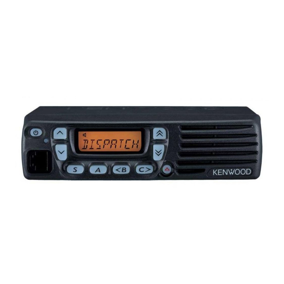
GETTING ACQUAINTED RONT ANEL q q q q q (Power) switch Press to switch the transceiver ON or OFF. w w w w w Press to activate its programmable function {page 8}. The default setting is Volume Up. e e e e e Press to activate its programmable function {page 8}. - Page 12 !1 !1 !1 !1 !1 A key Press to activate its programmable function {page 8}. The default setting is None (no function). !2 !2 !2 !2 !2 <B key Press to activate its programmable function {page 8}. The default setting is Channel Down.
-
Page 13: Display
ISPLAY l l a e l i e l i n i l v i t y t i v i t c i l v i t y l t ANEL Antenna connector External speaker jack Power input connector... -
Page 14: Programmable Functions
PROGRAMMABLE FUNCTIONS , S, A, <B, C>, and keys can be programmed with the functions listed below: • 2-tone Encode Press to enter 2-tone Encode Select mode. Refer to page 19 for details. • Press to activate the auxiliary port. Press again to deactivate the auxiliary port. - Page 15 • None No function is programmed onto the key. • Operator Selectable Tone Press to enter OST (Operator Selectable Tone) Select mode. Refer to page 16 for details. • Public Address Press to activate the Public Address (PA) system. Refer to page 24 for details.
-
Page 16: Basic Operations
BASIC OPERATIONS ON/ OFF WITCHING OWER Press the switch to switch the transceiver ON. • A beep sounds. If programmed, an 8-character power-on message is also momentarily displayed. • If the Transceiver Password function is programmed, “ ” will appear on the display when the power is turned ON. -
Page 17: Selecting A Zone And Channel
ELECTING A ONE AND HANNEL Select the desired zone using the keys programmed as Zone Up and Zone Down. • The default setting for the key is Zone Up. • The default setting for the key is Zone Down. Select the desired channel using the keys programmed as Channel Up and Channel Down. -
Page 18: Scan
SCAN Scan is useful for monitoring signals on the transceiver channels. Scan can be used as either Single Scan or Multi Scan and is programmed by your dealer. • Single Scan monitors only the channels of a single zone. To monitor other zones, press the Zone Up or Zone Down key during Scan. -
Page 19: Add To Scan / Delete From Scan
DD TO ELETE FROM Depending on how your transceiver has been set up, a key may have been programmed with the Scan Del/Add function. This function allows you to scan only those channels which you desire. To add or remove a channel to/from the Scan list, select the desired channel then press the Scan Del/Add key. -
Page 20: Dtmf Calls
DTMF CALLS Note: To make DTMF calls, you must have an optional microphone with a DTMF keypad. & S TORE 1 Enter the desired digits on the microphone keypad. • You can enter a maximum of 16 digits (0 ~ 9, A ~ D, , and #). -
Page 21: Dialing Stored Dtmf Numbers
DTMF N IALING TORED UMBERS 1 Press the microphone key. • “ ” appears on the display. 2 Enter the desired memory location number (1 ~ 9). • The digits stored in the selected location number appear on the display. •... -
Page 22: Quiet Talk (Qt)/ Digital Quiet Talk (Dqt)
QUIET TALK (QT)/ DIGITAL QUIET TALK (DQT) Your dealer may have programmed QT or DQT signaling on your transceiver channels. A QT tone/ DQT code is a sub-audible tone/code which allows you to ignore (not hear) calls from other parties who are using the same channel. When a channel is set up with a QT tone or DQT code, squelch will only open when a call containing a matching tone or code is received. -
Page 23: Code Squelch (Id Code)
CODE SQUELCH (ID CODE) Code Squelch is enabled or disabled by your dealer. This function turns the transceiver squelch OFF only when it receives the DTMF ID code that has been set up in your transceiver. Transceivers that do not transmit the correct code will not be heard. -
Page 24: Selective Call
SELECTIVE CALL Selective Call is enabled or disabled by your dealer. This function is similar to Code Squelch {page 17}. The differences from Code Squelch are: • You can send or receive Status codes containing up to 5 digits. • Selective Call opens the squelch only when the transceiver receives a predetermined DTMF code in the correct sequence (3-digit or 4-digit ID code —... -
Page 25: 2-Tone Signaling
2-TONE SIGNALING 2-tone Signaling is enabled or disabled by your dealer. This function opens the squelch only when the transceiver receives the 2 tones corresponding to the 2-tone code set up on your transceiver. Transceivers that do not transmit the correct tones will not be heard. -
Page 26: Fleetsync: Alphanumeric 2-Way Paging System
FleetSync: ALPHANUMERIC 2-WAY PAGING FUNCTION FleetSync is an Alphanumeric 2-way Paging Function and is a protocol owned by KENWOOD Corporation. FleetSync enables a variety of paging functions on your transceiver, some of which depend on dealer programming. GPS R EPORT... -
Page 27: Status Message
TATUS ESSAGE You can send and receive 2-digit Status messages which may be decided in your talk group. Messages can contain up to 16 alphanumeric characters. Status messages range from 10 to 99 (80 ~ 99 are reserved for special messages). A maximum of 5 received messages can be stored in the stack memory of your transceiver. -
Page 28: Emergency Operation
EMERGENCY OPERATION If your transceiver has been programmed with the Emergency function, you can make emergency calls. 1 Press and hold the key programmed as Emergency. • Depending on the delay time programmed into your transceiver, the length of time you must hold the Emergency key will vary. -
Page 29: Advanced Operations
ADVANCED OPERATIONS ROUND You may occasionally experience an interruption in service (due to a power failure, etc.). During such an occurence, you can continue communication by using the Talk Around feature if it has been programmed by your dealer. Talk Around allows you to communicate directly with other transceivers without the use of a repeater. -
Page 30: Public Address (Pa) System
(PA) S UBLIC DDRESS YSTEM To use the Public Address system, your dealer must install an optional KAP-2 unit and an external speaker. This function causes all audio input via the microphone to be amplified and output from the external speaker. To use the PA system: 1 Press the key programmed as Public Address. -
Page 31: Voice Scrambler
OICE CRAMBLER Note: There are 2 options for using the scrambler. Your dealer can activate or deactivate the built-in scrambler function of the transceiver, or they can add a more secure optional scrambler board to your transceiver. Ask your dealer for details. Although the built-in scrambler function does not offer complete privacy with your calls, it does prevent others from easily listening in on your calls. -
Page 32: Background Operations
BACKGROUND OPERATIONS (TOT) IMER The purpose of the Time-out Timer is to prevent any caller from using a channel for an extended period of time. If you continuously transmit for a period of time that exceeds the programmed time, the transceiver will stop transmitting and an alert tone will sound.