Sharp MX-3500N Service Manual
Digital full color multifunctional system
Hide thumbs
Also See for MX-3500N:
- Brochure & specs (8 pages) ,
- Service manual (6 pages) ,
- User manual (843 pages)
Table of Contents
Advertisement
Quick Links
TopPage
Note For Servicing . . . . . . . . . . . . . . . i
[1]
Product Outline . . . . . . . . . . . . 1-1
[2]
SPECIFICATIONS . . . . . . . . . . . . . . 2-1
[3]
Consumable Parts . . . . . . . . . . 3-1
[4]
UNPACKING AND INSTALLATION
* For how to unpacking and installation,
refer to the installation manual
(00ZMX3500/I1E).
[5]
EXTERNAL VIEW AND INTERNAL
STRUCTURE . . . . . . . . . . . . . . . . . . 5-1
[6]
Adjustments . . . . . . . . . . . . . . . . 6-1
[7]
Simulation . . . . . . . . . . . . . . . . . . 7-1
[8]
Self Diag AND
Trouble Code . . . . . . . . . . . . . . . 8-1
[9]
Maintenance . . . . . . . . . . . . . . . . 9-1
[10] ROM VERSION-UP . . . . . . . . . . . . 10-1
[11] ELECTRICAL SECTION. . . . . . . . . 11-1
[12] OTHERS. . . . . . . . . . . . . . . . . . . . . 12-1
Parts marked with "
" are important for maintaining the safety of the set. Be sure to replace these parts with
specified ones for maintaining the safety and performance of the set.
SERVICE MANUAL
DIGITAL FULL COLOR
MULTIFUNCTIONAL SYSTEM
MX-3500N/4500N
MX-3501N/4501N
MODEL
SHARP CORPORATION
CODE: 00ZMX3500NS2E
● DETAILS OF EACH SECTION
[A] EXTERNAL OUTFIT . . . . . . . . . . . . .A-1
[B] Operation Panel . . . . . . . . . . . .B-1
[C] Scanner Section . . . . . . . . . . . C-1
[D] MANUAL PAPER FEED
SECTION . . . . . . . . . . . . . . . . . . . . D-1
[E] Tray Paper Feed Section . . . .E-1
[F] Paper Transport Section . . .F-1
[G] Duplex Section . . . . . . . . . . . . G-1
[H] Lsu Section . . . . . . . . . . . . . . . . H-1
[i]
PHOTOCONDUCTOR SECTION. . . i-1
[J]
TONER SUPPLY SECTION . . . . . . . J-1
[K] Developing Section . . . . . . . . .K-1
[L]
TRANSFER SECTION . . . . . . . . . . . L-1
REGISTRATION SENSOR
SECTION . . . . . . . . . . . . . . . . . . . . M-1
[N] FUSING SECTION . . . . . . . . . . . . . N-1
[O] PAPER EXIT SECTION . . . . . . . . . O-1
[P] Drive Section . . . . . . . . . . . . . . .P-1
[Q] PWB SECTION. . . . . . . . . . . . . . . . Q-1
[R] FAN AND FILTER SECTION . . . . . R-1
[S] SENSOR, SWITCH SECTION . . . . .S-1
This document has been published to be used
for after sales service only.
The contents are subject to change without notice.
Advertisement
Table of Contents

Related Manuals for Sharp MX-3500N


Summary of Contents for Sharp MX-3500N
-
Page 1: Service Manual
TopPage SERVICE MANUAL CODE: 00ZMX3500NS2E DIGITAL FULL COLOR MULTIFUNCTIONAL SYSTEM MX-3500N/4500N MX-3501N/4501N MODEL CONTENTS ● DETAILS OF EACH SECTION NOTE FOR SERVICING ....i PRODUCT OUTLINE ... . 1-1 [A] EXTERNAL OUTFIT . -
Page 2: Table Of Contents
CONTENTS NOTE FOR SERVICING TRAY PAPER FEED SECTION 1. Precautions for servicing......i 1. Electrical and mechanism relation diagram ..E-1 2. -
Page 3: Note For Servicing
Do not get them in the eyes. If toner, developer, or ink enters you eyes, wash it away with water immediately, and consult a doctor if necessary. The machine has got sharp edges inside. Be careful not to damage fingers when servicing. Place of much vibrations Do not throw toner or a toner cartridge in a fire. - Page 4 Place of direct sunlight. Plastic parts and ink may be deformed, discolored, or may undergo qualitative change. It may cause a breakdown or copy dirt. Place which is full of organic gases such as ammonium The organic photoconductor (OPC) drum used in the machine may undergo qualitative change due to organic gases such as ammonium.
-
Page 5: Product Features
In addition, the employment of ether] are limited to the regulated level or less.) "Auto Color" function, Sharp's unique auto recognition func- tion, reproduces documents of difficult reproduction. The power consumption for FAX standby with the power OFF is 1W or less, reducing energy expenses of nighttime and load to the environment. -
Page 6: Configuration
(MX-PNX1D) 4. Exit tray unit 5. Paper pass unit (MX-TRX2) (MX-RBX1) Copier/Printer Copier/Printer /Scanner model /Scanner model 11. Staple cartridge (MX-3500N) (MX-3501N) (Approx. 5000 x 3) (MX-4500N) (MX-4501N) (AR-SC2) 9. Punch module 2-hole (AR-PN1A) ● 1. Stand/1x500 sheet 2. Stand/2x500 sheet 3. - Page 7 : May 15 2006 B. Machine configuration MX-3500N/MX-4500N MX-3501N/MX-4501N Copier memory (Local memory) (MB) Printer memory (System memory) (MB) Copier GDI printer PCL printer PS printer OP*1 EFI printer Main body LCD MONOCHROME HVGA 8.9" OP*2 Scanner Filing RSPF –...
-
Page 8: Basic Specifications
16K, 16KR, 11 x 17, 8.5 x 14, 8.5 x 13, Color support Full color 8.5 x 11, 8.5 x 11R, 7.25 x 10.5R, 5.5 x 8.5R (Not Envelope, Extra) (2) Engine speed Productivity Non-offset MX-3500N 35cpm a. Tray1 – 4 (Main unit), LCC (A4, 8.5x11) (Normal Color 35cpm output) - Page 9 Standby : 55dB or less Gloss Paper (13) Dimensions Paper capacity Standard paper: 100 sheets Envelope: 20 sheets MX-3500N/MX-4500N MX-3501N/MX-4501N OHP: 20 sheets Heavy paper: 40 sheets Outer dimensions 645 x 670 x 950mm 645 x 670 x 960mm Tab paper: 20 sheets...
- Page 10 (6) Paper exit tray unit (Right tray) Document 1-side Thin paper 35 – 49g/m (9 – 13 lbs) weights * Option (MX-TRX2) Plain paper 50 – 128g/m (13 – 34 lbs) 2-side 50 – 128 g/m (13 – 34 lbs) Form Exit tray unit Document carrying...
- Page 11 (2) Original cover Document 1-side Thin paper 35 – 49g/m (9 – 13 lbs) weights Plain paper 50 – 128g/m (13 – 34 lbs) Scan Range 297 x 432mm 2-side 50 – 128 g/m (13 – 34 lbs) Original Cover Left back as standard Document carrying Maximum: 150 sheets (80g/m...
-
Page 12: Functional Specifications
Heavy paper (Postcard LOW) *1 Heavy paper (Other sizes) *1: Switched by the service simulation setting (2) First copy time (3) Job speed a. Document changing speed (in copy mode) MX-4500N (RSPF), MX-3500N (RSPF), MX-4501N (DSPF) MX-3501N (DSPF) Platen/RSPF/DSPF MX-4500N/MX-4501N MX-3500N/MX-3501N Color... - Page 13 (7) Copy magnification ratio (11) Copy functions Copy Normal: 1:1±0.8% Function Automatic paper Yes (Mixed/random size feeding magnification ratio selection supported) AB series: 25%, 50%, 70%, 81%, 86%, 100%, 115%, 122%, 141%, 200%, 400% Automatic magnification selection Inch series: 25%, 50%, 64%, 77%, 100%, 121%, 129% , 200%, 400% Paper type select Type setting allowed...
- Page 14 B. Image send function Mode Scanner Internet Fax Density adjustment Auto + 5 steps Auto + 5 steps (1) Mode (The image quaity of "Auto" is the same as that Scanner Scan to e-mail of "Manual = 3" when Scan to Desktop selecting full color/ Scan to FTP grayscale.)
- Page 15 Mode Scanner Internet Fax Scanner Internet Fax Other functions Mail footer preset (*2), inhibition of address Automatic reduction registration from the main unit, inhibition of address setting upon receiving registration from a Web screen, inhibition of registration from the network scanner tool, Automatic reduction inhibition of "Resend"...
- Page 16 m. Others Scanner Internet Fax 2 in 1 Mode Scanner Internet FAX (Allowed for Fax / PC-Internet Fax Internet Fax Trial mode broadcast) Scanner: No (Standard) Background removal Meta data: Yes (Only color and gray scale) C. PC-Fax functions Card scan Yes (Equivalent or enlargement up to the paper (1) PC-Fax/PC-Internet Fax operating environment width.
- Page 17 NetWare Gamma adjustment environment Color matching None/For Printer/For CRT/For LCD/ICM UNIX LPR/LPD command-compatible print channel Edge emphasis None/Normal/Sharp/Blur Print channel in compliance with IPP1.0 Black-white inversion PAP: Print channel to be used for Machintosh environment Selection of illuminant Yes (Red/Green/Blue/White)
- Page 18 Custom profile can upload by Web setting. (The attached ICC profile on devices is available.) <Output Profile> There is no user selection for output profile. Sharp provides Custom profile. Upload of profile supports by service. The tool is set on the Web (service setting). The concrete method of profile making is to be considered separately.
- Page 19 (9) Windows driver function b. Paper feed system PCL5-c/6: Standard Function PCL5-c/6 PS: Option (Installation of the PS3 expansion kit (MX-PKX1) are Paper Size A2 (Fit To Page) required.) (PCL6 only) 12 x 18, A3, A4, A5, B4, B5, 11 x 17, 8.5 x 11, 8.5 x 14, a.
- Page 20 Function PCL5-c/6 Saturation (Cannot be specified 0-100 with the monochrome mode) * Some OS may not allow one- number-to-next specification for setup values. Color Balance (RGB) 0-100 (Cannot be specified with the monochrome mode) * Some OS may not allow one- number-to-next specification for setup values.
- Page 21 (10) Macintosh driver functions Function OS9 PPD OSX 10.1 OSX 10.2/3/4 Rendering Intent Perceptual matching a. Frequently used functions * Specification Relative colorimetric depending on OS Saturation matching Function OS9 PPD OSX 10.1 OSX 10.2/3/4 Absolute colorimetric Copies 1-999 ICC Profile Selection Source Source Orientation...
- Page 22 • European ROHS regulations user folder • Chinese ROHS Number of users Depends on the number of user registrations. allowed for registration (Maximum of 200 users) • WEEE (Following to SHARP super green product declaration.) MX3500N SPECIFICATIONS 2 – 15...
-
Page 23: Ambient Conditions
3. Ambient conditions A. Operating environmental conditions (Main unit) Temperature: 10°C – 35°C, Humidity: 20 – 85%RH Air pressure: 590 – 1013hPa (height: 0 – 2000m) Humidity (RH) B. Ambient conditions for transporting (Main unit) –20°C to 45°C (No condensation) Humidity (RH) C. -
Page 24: Supply System Table
MX3500N [3] CONSUMABLE PARTS Service Manual 1. Supply system table A. USA/Canada/South and Central America Item Content Life Model Name Remarks Toner Cartridge (Black) Toner Cartridge (Black) with IC Chip 36K *1 MX-45NTBA * Life: A4/Letter size (Black toner : Net 880g) at Area Coverage 5% (Reference: 30K for A4/Letter 6%) Toner Cartridge (Cyan) -
Page 25: Maintenance Parts List
: Jan. 15 2006, : Jul. 15 2006, : Feb. 15 2007 D. Middle East/Africa/Israel/Philippines/Taiwan Item Content Life Model Name Remarks Toner Cartridge (Black) Toner Cartridge (Black) with IC Chip 36K *1 MX-45FTBA * Life: A4/Letter size (Black toner : Net 880g) at Area Coverage 5% (Reference: 30K for A4/Letter 6%) Toner Cartridge (Cyan) - Page 26 : Jan. 15 2006, : Jul. 15 2006, : Feb. 15 2007 B. Europe/UK/Australia/New Zealand/Taiwan Item Content Life Model name Remarks Upper heat roller kit Upper heat roller 300K MX-450UH Fuser gear Upper separation pawl Upper separation pawl SP-N Upper thermistor sub Upper thermistor side Upper thermistor CJ Upper heat roller bearing...
-
Page 27: Production Number Identification
3. Production number identification C. Toner cartridge The label indicating the management number is attached to the A. Drum cartridge side of the toner cartridge. Part name The lot number is of 10 digits. Each digit indicates the content as Destination follows. -
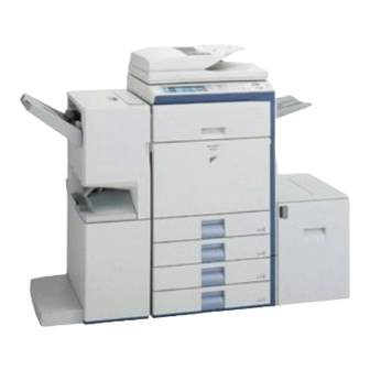
Page 28: Identification Of Each Section And Functions
This automatically feeds and scans multiple originals. Both sides of two-sided Installed standard on the (Reversing single pass feeder) originals can be automatically scanned. MX-3500N/4500N. Front cover Open this cover when turning ON/OFF the main power switch or replacing the toner cartridge. - Page 29 B. Internal structure When using the MX-3500/4500 Series Name Function/ Operation Note Toner cartridge When the toner in a cartridge runs out, the cartridge must be replaced with a new cartridge of the same color. The shape of the toner cartridge varies slightly by model. Fusing section Fuses images transferred on paper by heat.
- Page 30 C. Automatic document feeder • MX-3500N/4500N • MX-3501N/4501N Name Function/ Operation Note Document feed roller Transports a document automatically. Document feed section cover This cover is opened when removing a paper jam or cleaning the document feed roller. Document guide Guides to scan a document properly.
- Page 31 D. Connectors Service-only connector Name Function/ Operation Note USB connector (Type A) Used to connect a USB hub or USB memory. USB connector (Type B) Used to connect a computer to use this machine as a printer. LAN connector Used to connect a LAN cable to use this machine in a network. MX3500N EXTERNAL VIEW AND INTERNAL STRUCTURE 5 –...
- Page 32 E. Operation panel PRINT DOCUMENT READY FILING DATA LINE IMAGE SEND DATA COPY SYSTEM JOB STATUS SETTINGS LOGOUT 14 15 16 Name Function/ Operation Note Touch panel A message or a key is displayed on the LCD screen. Touch the displayed key with your finger to perform various operations.
- Page 33 F. Print and send status (Job status) Complete job status screen SPOOL SPOOL JOB QUEUE SETS / PROGRESS STATUS JOB QUEUE JOB QUEUE COPY 020 / 001 COPYING COMPLETE COMPLETE COPY 020 / 000 PAPER EMPTY DETAIL DETAIL BBB BBB 020 / 000 WAITING PRIORITY...
- Page 34 G. Sensors OCSW MHPS TFD3 HPOS TFD2 POD3 POD2 APPD1 POD1 DSW_ADU 1TUD_CL 1TUD_K REGS_F/R DHPD_CL PCS_CL/K DHPD_K APPD2 TCS_Y TCS_M TCS_C TCS_K MPED MTOP2 PPD2 MTOP1 MPFD MPLD MPWD PPD1 TH_M/HUD_M CLUD1 CPFD1 CPED1 CSS1 CSS11 DSW_C CSS12 CSS13 CSPD1 CSS14 CLUD2...
- Page 35 Signal name Name Function/Operation Type NOTE MPWD Manual paper feed tray paper width Detects the manual paper feed tray paper width. Volume resistor detector MTOP1 Manual paper feed tray pull-out position Detects the manual paper feed tray paper pull-out Transmission type Manual paper detector 1 position (storing position).
- Page 36 H. Switches PWRSW DSW-R DHSW DSW-F 1TNFD Signal name Name Type Function/Operation Note 1TNFD Waste toner full detection switch Mechanical switch Detects the waste toner full. DHSW Dehumidifier heater switch Seesaw switch Turns ON/OFF the power lone of the dehumidifier heaters (Japan only) provided in the scanner (reading) section and the paper feed section.
- Page 37 I. Clutches and solenoids ADUGS 1TURC LSUSS1 PCSS MPGS MPFS MPUC CPUC1 CPFC CPUC2 Signal name Name Type Function/Operation Note 1TURC Primary transfer separation clutch Electromagnetic clutch Controls the primary transfer separation mode. CPFC Tray vertical transport clutch Electromagnetic clutch Controls ON/OFF of the paper transport roller in the paper feed tray section.
- Page 38 J. Drive motors WEBM TNM_Y ADUHM TNM_M TNM_C WTNM DVM_CL TNM_K DM_CL DM_K DVM_K ADULM CPFM CLUM1 CLUM2 Signal name Name Type Function/Operation Note ADULM ADU motor lower Stepping motor Drives the right door section. CLUM1 Paper tray lift-up motor (Paper DC brush-less motor Drives the lift plate of the paper feed tray.
- Page 39 K. Lamps CCFT DL_Y DL_M DL_C DL_K HL_US HL_UM HL_LM Signal name Name Type Function/Operation Note CCFT LCD backlight CCFT cool cathode ray tube Backlight for the CCD Scanner lamp Xenon lamp Radiates lights onto a document for the CCD to scan document images.
- Page 40 : May 15 2006 L. Fans and filters POFM_R POFM_F LSUFAN PCSFM HDDFM CPUFM PSFM OZFM Signal name Name Function/Operation Note CPUFM Controller cooling fan motor Cools the controller PWB. HDDFM HDD cooling fan motor Cools the HDD. OZFM Ozone fan motor Exhausts ozone.
- Page 41 M. PWB control box Name Function/Operation Note RD I/F PWB Detects the sensors in the right door unit. Tray 1 detection PWB Detects the tray 1. Tray 2 detection PWB Detects the tray 2. DC power PWB Outputs the secondary side voltage. Driver main PWB Drives the transport motor and related sections.
- Page 42 Name Function/Operation Note SCAN IN PWB Rectifies the waveform of scanner image data. DOCC PWB Recognizes the document control pattern. Option BOOT ROM PWB Stores the program to boot the printer controller. PROGRAM ROM PWB Stores the program. SCN Flash ROM PWB Stores the scanner control program.
- Page 43 O. Gate Name Function/ Operation Note ADU gate Selects the paper path to transport paper to the duplex (ADU) section or to discharge paper to the right door. MX3500N EXTERNAL VIEW AND INTERNAL STRUCTURE 5 – 16...
- Page 44 P. Rollers Name Function/ Operation Note Paper feed roller (Manual paper feed tray) Feeds paper to the paper transport section. Separation roller (Manual paper feed tray) Separate paper to prevent against double feed. Paper pickup roller (Manual paper feed tray) Feeds paper to the paper feed roller.
- Page 45 Name Function/ Operation Note Transport roller 7 (Drive) Transports paper from the paper feed tray 1, 2, 3, and 4 to the transport roller 8. Transport roller 8 (Idle) Applies a pressure to paper and the transport roller to give paper the transport power of the transport roller.
-
Page 46: General
MX3500N [6] ADJUSTMENTS Service Manual 1. General Each adjustment item in the adjustment item list is associated with Unnecessary adjustments can be omitted. Even in this case, how- a specific Job number. Perform the adjustment procedures in the ever, the sequence from the smallest to the greatest Job number sequence of Job numbers from the smallest to the greatest. -
Page 47: Details Of Adjustment
Job No. Adjustment item list Simulation ADJ 20 Copy color balance/density adjustment ADJ 20I Copy color balance adjustment (Single color copy mode) (Normally 46-25 not required) ADJ 20J Auto color balance adjustment by the user (Copy color balance auto 26-53 adjustment enable setting and adjustment) ADJ 20K Background process condition setting in the color auto copy mode... -
Page 48: Developing Roller Main Pole Position Adjustment
Push the developing doctor in the arrow direction, and tighten Hold the thread and bring the needle near the developing the fixing screw of the developing doctor. (Perform the similar roller. (Do not use a paper clip because it will not provide a cor- procedure for the front frame and the rear frame.) rect position.) Mark the developing roller surface on the extension line of the... - Page 49 When [EXECUTE] key is pressed during rotation, the opera- ADJ 3 Toner density reference control tion is stopped and [EXECUTE] key returns to the normal dis- play. level setting If [EE-EU], [EE-EL], or [EE-EG] is displayed, setting of the ref- This adjustment must be executed in the following cases: erence toner density control value is not completed normally.
-
Page 50: Developing Bias Voltage Adjustment
Adjustment value Monitor (MC/DV high voltage PWB) Actual Item Mode Adjustment Default Monitor voltage voltage Connector range value (Specified value) 53.6 ± 1.61V MIDDLE MIDDLE SPEED GB_K Main charger grid voltage 230 – 850 CNMON –615V (Middle speed mode) 53.6 ± 1.61V MIDDLE SPEED GB_C Main charger grid voltage 230 –... - Page 51 Enter SIM8-1 mode. CLOSE SIMULATION NO.08-01 TEST DV SETTING AND OUTPUT A xxx MIDDLE SPEED DVB_K B xxx MIDDLE SPEED DVB_C MIDDLE SPEED DVB_M C xxx MIDDLE SPEED DVB_Y D xxx MIDDLE EXECUTE EXECUTE 10-key EXECUTE or after 30 sec. CLOSE SIMULATION NO.08-01 TEST...
-
Page 52: Transfer Voltage Adjustment
Remove the main unit rear cover. Check the monitor voltage with the digital multi-meter. If the monitor voltage is not in the range of the specified values shown in the table above, change the adjustment value and adjust again. If the specified value voltage is not obtained even though the adjustment value is changed, the following parts may be defective. -
Page 53: Color Image Density Sensor Calibration
Default Setting Default Actual output value Item Display Content range value setting range Actual output value TC1 LOW SPEED CL K Primary transfer COLOR Low speed 0 to 255 –500V to 5000V 4500V bias reference TC1 MIDDLE SPEED CL K Middle speed 0 to 255 –500V to 5000V... - Page 54 : Feb. 15 2006 Open the right cover unit (secondary transfer unit section). Adjustment Default Display/Item Content Open the process front cover, and pull out the primary transfer value range value belt unit. PCS_CL Color image density sensor 1 – 255 CARB OUT LED current adjustment target value...
-
Page 55: Image Skew Adjustment (Lsu Unit)
Display/Item Content Adjustment value range Default value PRO CON PCS_CL LED ADJ Color image density sensor light emitting quantity adjustment value 1 – 255 PCS _K LED ADJ Black image density sensor light emitting quantity adjustment value 1 – 255 PCS_CL DARK Color image sensor dark voltage 0 –... - Page 56 Check the printed black image for any skew (right angle). b) Measure the shortest distance between the cross pattern on the extended line of the vertical line and the paper side. Measure the right angle level by using the six cross patterns printed in black.
-
Page 57: Opc Drum Phase Adjustment (Auto Adjustment)
(Compare the front and the rear frame positions of the same- OPC drum phase adjustment (Auto color print color patterns. All the highest density sections of all adjustment) the print color patterns may not be aligned on a line. Compare only the same-color patterns.) Enter SIM50-22 mode. -
Page 58: Magnification Ratio Adjustment
OPC drum phase adjustment (Manual adjustment) Enter SIM44-31 mode. CLOSE SIMULATION NO.44-31 TEST DRUM POSITION SETTING PRINT MODE SET VALUE COLOR PAPERSELECT EXECUTE 10-key Each identification number ("1" – "8") is printed on each printed page of 8 adjustment patterns. CLOSE SIMULATION NO.44-31 TEST... - Page 59 Enter SIM50-10 mode. ADJ 9 Image off-center adjustment (Print engine section) CLOSE SIMULATION NO.50-10 TEST This adjustment must be executed in the following cases: PAPER CENTER OFFSET SETUP * When the LSU is replaced or removed. A xxx BK-MAG * When [ADJ8] print engine image magnification ratio (BK) (main scanning direction) is performed.
- Page 60 When the set value is changed by 1, the shift distance is Default Display/Item Content changed by about 0.1mm. range value Print off-center adjustment 1 – 99 Repeat procedures 3) – 7) until the conditions of procedure 5) value (ADU) are satisfied.
-
Page 61: Auto Adjustment
Adjustment Default 10-A Image registration adjustment (Main Display/Item Content value range value scanning direction, sub scanning direction) REGIST MAIN Image registration 1.0 – 199.0 (Auto adjustment) adjustment value (Main scanning direction) In this adjustment, the image registration adjustment in the main (Cyan) (R side) scanning direction and that in the sub scanning direction are exe- Image registration... - Page 62 Select the paper feed tray with A3 (11 x 17) paper in it by changing the value of set item H. Press [EXECUTE] key. The image registration adjustment pattern in the main scan- ning direction is printed. A: Rough adjustment pattern B: Fine adjustment pattern C: Adjustment range (0 ±...
- Page 63 (Measurement of the shift amount and the calculation of Measurement value: –27 (= –20 – 7) the adjustment value) Measurement of the shift amount * Measurement of the fine adjustment pattern The visually highest color density section is regarded as the center, and used as the measurement value.
- Page 64 Yellow Magenta Cyan MX3500N ADJUSTMENTS 6 – 19...
- Page 65 (Example) 10-C Image registration adjustment (Sub scanning direction) (Manual adjustment) Previous value before adjustment New adjustment value A: 100 A: 93 (= 100 – 7) Enter SIM50-21 mode. B: 112 B: 100 (= 112 – 12) C: 95 C: 96 (= 95 + 1) D: 98 D: 109 (= 98 + 11) CLOSE...
- Page 66 Check the rough adjustment and the fine adjustment print pat- Measurement value: –27 (= –20 – 7) tern positions of each color. The visually highest color density section is regarded as the center, and used as the measurement value. Rough adjustment Check that the rough adjustment print pattern is at print pattern check: the center for the rough adjustment reference...
-
Page 67: Scan Image Distortion Adjustment
Adjustment value calculation Add or subtract the shift amount calculated above to or from the current adjustment value, and the result value is used as the new adjustment value. Adjustment value = Current adjustment value + Shift amount (correction value) (When the shift amount (correction value) is plus) Adjustment value = Current adjustment value –... -
Page 68: Scan Image (Sub Scanning Direction) Distortion Adjustment
Turn the scanner drive pulley manually and shift the scanner With the scanner unit B in contact with both stoppers, fit the unit B to bring it into contact with the stopper. When the scan- edge of the scanner unit A with the right edge of the frame, and ner unit B is in contact with the two stoppers on the front and fix the scanner unit A with the fixing screw. -
Page 69: Scan Image (Main Scanning Direction) Distortion Adjustment
Set the test chart prepared in the procedure 1) on the docu- 11-C Scan image (main scanning direction) ment table. (Shift the test chart edge 30mm from the reference distortion adjustment position as shown below.) With the document cover open, make a copy on A3 (11"... -
Page 70: Ccd Unit Position Adjustment
Change the height balance of the scanner rail on the front ADJ 12 Scan image focus adjustment frame side. (CCD unit position adjustment) This adjustment is required in the following cases: * When the CCD unit is removed from the machine. * When the CCD unit is replaced. - Page 71 11) Slide the CCD unit in the arrow direction (CCD sub scanning direction) to change the installing position. When the copy image is longer than the original scale, shift the CCD unit in the direction B. When the copy image is shorter 100mm scale than the original scale, shift the CCD unit in the direction A.
-
Page 72: Scan Image Magnification Ratio Adjustment
Enter the simulation 48-1 mode. 14-A Scan image magnification ratio adjustment (Main scanning direction) (Document table mode) SIMULATION NO.48-01 CLOSE TEST Place a scale on the document table as shown in the figure MAGNIFICATION ADJUSTMENT below. A xx CCD(MAIN) B xx CCD(SUB) C xx SPF(MAIN) - Page 73 Select the adjustment mode OC with the scroll key. ADJ 16 Scan image off-center Enter the adjustment value with 10-key, and press [OK] key. adjustment The entered value is set. When the set value is increased, the main scanning print posi- This adjustment is required in the following cases: tion is shifted to the front side by 0.1mm.
-
Page 74: Copy Image Position, Image Loss Adjustment
Set A4 (11 x 8.5) paper to all the trays, and select the set item Select the adjustment item with the scroll key, and enter the J with the scroll key. Enter the value corresponding to the adjustment value and press [OK] key. adjustment target paper feed tray. - Page 75 Place a scale on the document table as shown in the figure Enter the simulation 50-1 mode. below. Place a scale so that it is in parallel with the scanning direction and that its lead edge is in contact with the document guide CLOSE SIMULATION NO.50-01 TEST...
-
Page 76: Copy Color Balance/Density Adjustment
Enter the simulation 50-05 mode. 18-B Copy image position, image loss adjustment (RSPF mode) (Refer to the MX-RPX1 SM.) SIMULATION NO.50-05 CLOSE TEST LEAD EDGE ADJUSTMENT VALUE (PRINTER) A xxx DEN-C ADJ 19 Print lead edge image position B xxx DEN-B C xxx FRONT/REAR... - Page 77 (The following items affect the copy color balance/density Default Display Content Set range adjustment, and must be checked and adjusted before execu- value tion of the image quality adjustments.) TN_LIFE Toner density life correction Normal Allow YES/NO setting (Inhibit: 1: NO) The following adjustment items must be adjusted properly.
- Page 78 (2) Flowchart of the copy color balance/density adjustment procedures START When in repair, check/maintenance (with replacing consumable parts) When in After After After cleaning After After install/repair/check replacing replacement scanner JOB No Work item Simulation replacing replacing (without replacing developer of the image (reading) OPC drum...
- Page 79 (from Previous page) (from Previous page) Perform ADJ 20B copy color balance/ density auto adjustment. (SIM 46-24) Can the Enter the SIM 46-24 mode and select copy color balance and A3 (11 x 17) paper. (Auto selection) density be adjusted to satisfactory levels with the fine adjustment? Press the EXECUTE key.
- Page 80 NOTE: For the color (gray) balance, use the servicing color test chart (UKOG-0283FCZZ) to check. (Color copy) Patch 1 is SHARP gray chart slightly copied. SHARP GRAY CHART Patch 2 is copied. If the SIT chart is not available, execute SIM 63-5 to set the CCD gamma to the default.
- Page 81 Press [EXECUTE] key. (A3 or 11" x 17" paper is automatically 20-B Copy color balance adjustment (Auto selected.) adjustment) The color patch image (adjustment pattern) is printed out. This adjustment is required in the following cases: Set the color patch image (adjustment pattern) paper printed in * When a consumable part (developer, OPC drum, transfer belt) is procedure 2) on the document table.
- Page 82 Press [OK] key on the operation panel. According to data of this adjustment, the initial setting of the High density Low density half tone image correction is performed. CLOSE CLOSE SIMULATION NO. 46-24 TEST ENGINE HALFTONE AUTO ADJUSTMENT CONFIRM THE ADJUSTED PATCH AND PRESS [OK] TO REGISTER THIS PATCH DATA mixed ,PRESS [REPEAT] TO CONTINUE THIS PROCEDURE.
-
Page 83: Copy Color Balance Adjustment (Manual Adjustment)
(Abnormal end (Auto transition)) b. Note for the color balance adjustment (Manual adjustment) The print engine section must have been adjusted properly. The CCD gamma adjustment must have been adjusted prop- CLOSE erly. SIMULATION NO.44-26 TEST HALF TONE DENSITY CORRECT EXECUTION Set the color patch image adjustment patter on the document [S_VALUE] table, and place 5 sheet of white paper on it. - Page 84 The density level of each color must be almost at the same (Abnormal end (Auto transition)) level. Patch B may not be copied. Patch A must not be copied. CLOSE SIMULATION NO.44-21 TEST When, however, the color balance is adjusted according to a HALF TONE PROCON STANDARD VALUE REGISTER request from the user, there is no need to set to the standard RESULT...
- Page 85 Make a copy of the servicing color test chart (UK0G- In the above three, only the service color balance target can be set 0283FCZZ) and a user's document according to necessity in to a desired level. the Text/Printed Photo mode (Manual) and check the adjust- This adjustment is required in the following cases: ment result again.
- Page 86 • Factory target in the copy color balance adjustment (SIM 46-24) By use of SIM 63-11, one of the following color balances can be set as the factory color balance target. Each of the three color balances cannot be changed. (Fixed) SIM63-8 Factory color balance target (DEF2) = Factory color balance target (DEF2)
- Page 87 Enter the SIM 63-7 mode. (Procedures to set the service color balance target and the color balance target for the user color balance adjustment to the same color balance as the factory color balance target) CLOSE This procedure must not be executed when the copy color balance SIMULATION NO.63-07 TEST was adjusted with SIM 46-21 to a unique color balance requested...
-
Page 88: Copy Density Adjustment (Each Monochrome Copy Mode) (Whole)
Select the copy mode to be adjusted with the scroll key. Enter the SIM 46-2 mode. Adjustment Default Display/Item (Copy mode) value range value CLOSE SIMULATION NO.46-02 TEST AUTO Auto 1 – 99 EXPOSURE ADJUSTMENT(B/W)[COPY] TEXT Text 1 – 99 AUTO1 TEXT/PRINTED Text/Printed Photo... - Page 89 Normally individual adjustments are not required. This adjustment Enter the adjustment value with 10-key and press [OK] key. is executed when there is a request from the user. When the adjustment value is increased, the density is Enter the SIM 46-10 mode. increased.
- Page 90 Enter the adjustment value with 10-key. 20-H Gamma/density adjustment in the text When the adjustment value of item A, C, or E is changed, the image edge section (Normally not required) gamma at the edge area of text and lines is changed. This adjustment is used to change the reproduction level of text When the adjustment value is increased, the image contrast at and outline to an optional level by changing the gamma and the...
- Page 91 Enter the adjustment value with 10-key. Select ENABLE or DISABLE with 10-key. When disabling, set to "0" (NO). Adjustment Default value Display/Item When enabling, set to "1" (Yes). value Press [OK] key. 0 – 255 When set to DISABLE, the menu of the user auto color calibra- GREEN 0 –...
- Page 92 : Feb. 15 2006 Enter the SIM 46-33 mode. Set item A (SW MODE1) – G (SW MODE7): Used to set Enable/Disable of the background delete function for various kinds of documents. When the value of the set item corresponding to the document SIMULATION NO.46 33 CLOSE TEST...
- Page 93 : Feb. 15 2006 Enter the SIM 46-33 mode. 20-L Color document identification level (ACS operation) setting When the machine is used with some adjustment values changed SIMULATION NO.46 33 CLOSE TEST from the default values, this adjustment is required in the following COLOR AUTO MODE ADJUSTMENT(ACS 4DIGIT UNDER) cases.
- Page 94 Large hue area Small hue area Hue area (Device setting ACS setting level (Judgment reference set value in the color auto mode)) Area level 5 Area level 4 Area level 3 Area level 2 Area level 1 ACS color judgment setting Can be set About 10mm x About 5mm x...
- Page 95 (2) Flow of printer color balance/density adjustment procedures Printer color balance/density adjustment START Process correction is forcibly performed. (SIM 44-6) Execute the half tone image correction. (SIM 44-26) Is PCL mode supported? Check the printer color balance/ density. (Check the test pattern of SIM 64-5.) Use SIM 67-25 to the color balance check sheet, and check the patch...
- Page 96 (from Previous page) (from Previous page) Perform ADJ 21B printer color balance/ density auto adjustment. (SIM 67-24) Can the Enter the SIM 67-24 mode and select printer color balance and A3 (11 x 17) paper. (Auto selection) density be adjusted to satisfactory levels with the fine adjustment? Press the EXECUTE key.
- Page 97 (3) Printer color balance/density check The print density must be changed gradually from the lighter level to the darker level. The density changing direction must not be (Note) reversed. Before checking the copy color balance and the density, be sure to The density level of each color must be almost at the same level.
- Page 98 Set the color patch image (adjustment pattern) paper printed in Press [OK] key on the operation panel. procedure 2) on the document table. Place the printed color patch image (adjustment pattern) paper so that the thin lines on the paper are on the left side. Place 5 CLOSE CLOSE SIMULATION NO.67-24...
- Page 99 (Method 2) (Normal end (Auto transition)) By printing the color balance adjustment sheet with SIM 67-25 and comparing each process (CMY) black patch color balance with the black patch, the color balance adjustment can be CLOSE SIMULATION NO.44-26 TEST checked more precisely. HALF TONE DENSITY CORRECT EXECUTION [S_VALUE] #1: 907, #2: 902, #3: 909, #4:921, #5:936...
- Page 100 c. Adjustment procedure Select the color to be adjusted with the color select key, and select the adjustment point with the scroll key. Enter the SIM 67-25 mode. Enter the adjustment value with 10-key and press [OK] key. The adjustment value is set in the range of 245 – 755 (1 – 999).
- Page 101 (Abnormal end (Auto transition)) This adjustment is required in the following cases. * When the copy color balance/density adjustment (manual adjust- ment) is executed with SIM 67-25. CLOSE * When a U2 trouble occurs. SIMULATION NO.44-26 TEST HALF TONE DENSITY CORRECT EXECUTION * When the MFP PWB is replaced.
- Page 102 • Relationship between the factory target and the service target and the color balance target for the user color balance adjustment in the printer color balance adjustment (SIM 67-24) Color balance target in the copy color balance automatic adjustment (SIM 67-24) Use SIM 67-26 to select one of the three kinds of Factory setting...
- Page 103 If a considerable time has passed after completion of the color bal- Press [REPEAT] key, set the second color patch image ance adjustment (Manual) with SIM 67-25, the color balance of the (adjustment pattern), and execute the procedure 5) again. adjustment pattern at the time of adjustment differs from the color balance of the adjustment pattern printed after a considerable time.
- Page 104 * When the MFP PWB is replaced. ADJ 22 Fusing paper guide position * When the EEPROM on the MFP PWB is replaced. adjustment b. Setting procedure Enter the SIM 26-54 mode. This adjustment must be executed in the following cases: * When the fusing section is disassembled.
- Page 105 Slowly tilt the document detection arm unit in the arrow direc- Execute the sensor adjustment without document. tion. Loosen the original cover switch actuator adjustment With the document cover open, without placing a document on screw so that the display OCSW is returned to the normal dis- the table glass, press [EXECUTE] key.
- Page 106 Set the manual paper feed guide to the minimum width posi- pressed. tion. * When pressing the touch panel, never use a sharp tip (such as a needle or a pin). ADJ 27 Image loss, void area, image...
- Page 107 Press [OK] key. 27-A Print image main scanning direction image The adjustment result becomes valid. magnification ratio automatic adjustment Enter the SIM50-28 mode. Select [BK-MAG ADJ] with the key button. CLOSE SIMULATION NO.50-28 TEST AUTO IMAGE POSITION ADJUSTMENT SERVICE BK MAG : ** |**| SIMULATION NO.50-28 CLOSE...
-
Page 108: Automatic Adjustment
Press [EXCUTE] key. Set the adjustment pattern on the document table. (Any direc- tion) The adjustment pattern is printed out. Note: Fit the adjustment pattern correctly with the document Set the adjustment pattern on the document table. (Any direc- guide. tion) Note: Fit the adjustment pattern correctly with the document guide. - Page 109 MX3500N [7] SIMULATION Service Manual 1. General There are the following simulation functions for grasping the machine operating conditions, troubleshooting, early detection of trouble causes, speedy setting and adjustments, and improve- ments in servicing. Various adjustments Setting of the specifications and functions Canceling troubles Operation check Counters check, setting, clear...
-
Page 110: System Settings
Basic operation flowchart START (Copy mode) Press the Program key. Press the asterisk (*) key. Press the clear key. Press the Program key. Standby for entry of Press the SYSTEM SIM code. SETTINGS key Enter the main code of SIM with the 10-key. The main code of SIM is displayed. -
Page 111: List Of Simulation Codes
2. List of simulation codes Code Function (Purpose) Section Purpose Main Used to check the operations of the scanner unit and its control circuit. Optical (Image scanning) Operation test/check Used to check the operation of sensor and detector in the scanning (read) Optical (Image scanning) Operation test/check section and the related circuit. - Page 112 Code Function (Purpose) Section Purpose Main Used to check the system configuration (option, internal hardware). – Adjustment/Setup/Operation data check Used to check the use frequency (send/receive) of FAX. (Only when FAX is Adjustment/Setup/Operation installed) data check Used to check the RSPF/DSPF misfeed positions and the number of misfeed at RSPF/DSPF Adjustment/Setup/Operation each position.
- Page 113 Code Function (Purpose) Section Purpose Main Used to set the FSS functions (initializing, call, toner order auto send). Communication (RIC/ Setting MODEM) Used to set the tag number. Communication (RIC/ Setting MODEM) Used to set YES/NO of the manual service call. Communication (RIC/ Setting MODEM)
- Page 114 Code Function (Purpose) Section Purpose Main Used to check the toner patch image density level of each color in half tone Process Adjustment/Setup/Operation image forming section correction (process correction). (This simulation is used data output/Check (Display/Print) to check that the correction is normally executed or not.) (This simulation is not used in the market.) Process Adjustment/Setup/Operation...
- Page 115 Code Function (Purpose) Section Purpose Main This adjustment is executed when a satisfactory result is not obtained when a RSPF/DSPF/Scanner Adjustment different copy magnification ratio is specified and copying is made after adjustment of the sub scanning direction image magnification ratio with SIM 48- When there is an error in the copy magnification ratio in reduction copy, the adjustment value of high speed mode is adjusted.
- Page 116 Used to check the following values related to shading for RGB and OC/RSPF/ Scanner (Exposure) Adjustment/Setup/Operation DSPF. (3 x 2 = 6 kinds) data output/Check (Display/Print) Used to execute shading forcibly (MX-3500N/4500N). Scanner Adjustment Used to execute shading forcibly (MX-3501N/4501N). Scanner...
-
Page 117: Details Of Simulation
Code Function (Purpose) Section Purpose Main Used to clear the printer calibration value. Printer Data clear Used to set YES/NO of screen color change for each object. – Setting Used to execute the gamma correction between printer screens. (for PCL) Printer Adjustment Used to execute the gamma correction between printer screens. - Page 118 SPLS1 SPLS2 Select the operation mode with the buttons on the touch panel. Select the aging mode with [1SIDE] and [2SIDE] buttons on the touch panel (MX-3500N/4500N only). (MX-3501N/4501N) Select the magnification ratio with [ZOOM] button on the touch panel.
- Page 119 (MX-3500N/4500N) <Saddle finisher (MX-FNX2)> SPFM RSPF transport motor FJPID Interface transport unit entry port detection SPRM_F RSPF paper feed reverse motor normal rotation FJPOD Interface transport unit exit port detection SPRM_R RSPF paper feed reverse motor reverse rotation FJPDD Interface transport unit cover detection...
- Page 120 <Inner finisher punch unit (MX-PNX1A/B/C/D)> <4K finisher saddle unit> FPRPD Punch rear position detection FSPIND Saddle entry port paper detection FPUC Punch unit connection detection FSPDD Saddle paper exit detection FPHPD Punch HP detection FSTPD Saddle tray paper detection FPSHPD Punch horizontal resist HP detection FS1PD Saddle paper detection 1...
- Page 121 <When the 4K saddle finisher/saddle section> Purpose Operation test/check FSIFM Saddle entry port transport motor FSFM Saddle transport motor Function (Purpose) Used to check the operation of the load in FSFOM Paper folding motor the finisher and the control circuit. FSGM Guide motor Section...
- Page 122 [Screen (Saddle finisher (MX-FNX2) installed)] Default Item Display Item Set range value PUNCH HOLE Punch hole position 0 to 100 adjustment CLOSE SIMULATION NO.03-10 TEST <Inner finisher (MX-FNX1)> FINISHER ADJUSTMENT A 200 SADDLE POSITION Default Item Display Item Set range B 200 FOLDING POSITION value...
- Page 123 L24VM LCC 24V power monitor LLSW LCC upper limit SW Purpose Operation test/check LPUSW LCC paper upper surface detection SW Function (Purpose) Used to check the operations of the LRRSW LCC reverse winding detection SW clutches and the related circuits. Section Desk/Large capacity tray (LCC) Item...
- Page 124 The selected discharge lamp is lighted. Purpose Operation test/check DL_K Discharge lamp K DL_C Discharge lamp C Same control Function (Purpose) Used to check the operation of the heater DL_M Discharge lamp M lamp and the control circuit. DL_Y Discharge lamp Y Section Fusing Item...
- Page 125 CLOSE SIMULATION NO.06 01 TEST FEED OUTPUT CHECK POMF POMR Purpose Setting CPFM CPFC 1TURC PCSS Function (Purpose) Used to set the operating conditions of WTNM CLUM1 CPUC1 CLUM2 aging. CPUC2 MPUC Section Other EXECUTE Item Operation Operation/Procedure Select the target to be set with buttons on the touch panel. Purpose Operation test/check Press [EXECUTE] button.
- Page 126 Select a target item to be adjusted with [↑] [↓] buttons. Enter the adjustment value with 10-key. Purpose Operation display Press [EXECUTE] button. Function (Purpose) Used to display the warm-up time. The set value is saved and the voltage corresponding to the set value is outputted for 30 sec.
- Page 127 The set value is saved and the voltage corresponding to the (MX-4500N/ SPEED bias set value at set value is outputted for 30 sec. 4501N only) GB_K high speed When [EXECUTE] button is pressed, the output is terminated. (MX-3500N/3501N) Default Setting Default Actual output value Item Display Content...
- Page 128 Default Setting Default Actual output value Item Display Content range value setting range Actual output value TC2 PLAIN CL SPX Secondary transfer COLOR Normal Front surface 51 to 255 2µA to 45µA 20µA bias reference paper TC2 PLAIN CL DPX Back surface 51 to 255 2µA to 45µA...
- Page 129 TNM_K Toner motor K TNM_C Toner motor C TNM_M Toner motor M 15-- TNM_Y Toner motor Y Purpose Clear/cancel (Trouble etc.) Function (Purpose) Used to cancel the self-diag "U6-09" (large CLOSE SIMULATION NO.10-01 TEST capacity paper feed tray) trouble. TONER MOTOR ACTIVATION Section TNM_K TNM_C...
- Page 130 COPY(BW) Black copy counter COPY(COL) Color copy counter CLOSE COPY(2COL) 2-color copy counter SIMULATION NO.17 TEST COPY(SGL_COL) Single color copy counter PF TROUBLE CANCELLATION PRINT(BW) Black print counter PRINT(COL) Color print counter DOC FIL(BW) Black document filing print counter DOC FIL(COL) Color document filing print counter DOC FIL(2COL) 2-color document filing print counter...
-
Page 131: Paper Jam Code
22-5 Purpose Others CLOSE SIMULATION NO.22-02 TEST Function (Purpose) Used to check the ROM version of each JAM/TROUBLE COUNTER DISPLAY unit (section). MACHINE JAM : 00000000 Section — RSPF/DSPF JAM : 00000000 Item Software TROUBLE : 00000000 Operation/Procedure The ROM version can be checked with [↑] [↓] buttons. When there is any problem in the software, use this simulation to check the ROM version of each section and revise the version if necessary. - Page 132 Press [COLOR] or [BLACK] button to print. MACHINE MX-3500FN Machine MX-4500FN RSPF/DSPF Document feed quantity MX-3501FN SCAN Number of scan MX-4501FN STAPLER Staple counter MX-3500N PUNCHER Puncher counter MX-4500N STAMP Stamp counter MX-3501N SADDLE STAPLER Saddle staple counter MX-4501N OC_OPEN OC open/close counter RSPF/DSPF...
- Page 133 CLOSE SIMULATION NO.22-10 SIMULATION NO.22 12 CLOSE TEST TEST CLOSE MACHINE SYSTEM MACHINE MX-3500N PUNCHER MX-PNX1A RSPF/DSPF MX-RPX1/STANDARD FINISHER MX-FNX1 STAMP AR-SU1 MX-FXX1 DESK MX-DEX3 FAX2 MX-FLX1 MX-LCX1 FAX MEMORY : AR-MM9 22-11 22-13 Purpose Adjustment/Setup/Operation data check Purpose Adjustment/Setup/Operation data check...
- Page 134 22-19 All custom setting list ALL CUSTOM All custom setting list SETTING LIST Purpose Adjustment/Setup/Operation data check Printer test page PCL SYMBOL SET PCL symbol set list Function (Purpose) Used to check the values of the counters LIST related to the scan mode and the internet PCL INTERNAL FONT PCL internal font list FAX mode.
- Page 135 Press [YES] button. The target counter is cleared. MACHINE Machine JAM counter 23-2 RSPF RSPF JAM counter (MX-3500N/4500N only) DSPF DSPF JAM counter (MX-3501N/4501N only) Purpose Adjustment/Setup/Operation data check TROUBLE Trouble counter Function (Purpose) Used to check the trouble history of paper jam and misfeed.
- Page 136 24-5 RSPF/DSPF SPF counter SCAN Scan counter Purpose Data clear STAPLER Staple counter Function (Purpose) Used to clear the developer counter. (After PUNCHER Puncher counter replacement developer, clear STAMP Stamp counter counter.) SADDLE STAPLER Saddle staple counter Section — OC_OPEN OC open/close counter Item Counter...
- Page 137 24-7 24-10 Purpose Data clear Purpose Data clear Function (Purpose) Used to clear the OPC drum counter. (After Function (Purpose) Used to clear the FAX counter. (Only when replacement of the OPC drum, clear the FAX is installed) counter.) Section —...
- Page 138 SCAN TO HDD_CL Scan to HDD record quantity (COLOR) SCAN TO HDD_2CL Scan to HDD record quantity (2-color) SCAN TO HDD_SGL Scan to HDD record quantity (Single color) 25-1 Purpose Operation test/Check CLOSE SIMULATION NO.24 15 TEST Function (Purpose) Used to check the operations of the devel- NETWORK SCANNER COUTNER DATA CLEAR oping section.
- Page 139 Display Default 26-2 Display items Item descriptions range value Purpose Setting AT DEVE ADJ_H_K Automatic developer 1 – 255 (MX-4500N/4501N only) adjustment value at Function (Purpose) Used to set the paper size of the large high speed capacity tray (LCC). (When the paper size AT DEVE VO_L_K Automatic developer 1 –...
- Page 140 Button Item Content Default display COUNTUP FUSER_IN The charging timing is when EXIT_OUT CLOSE SIMULATION NO.26 05 TEST TIMING1 passing the sensor paper lead A3(11 17) COUNTUP edge after fusing. TOTAL(B/W) FUSER_OUT The charging timing is when TOTAL(COL) passing the sensor paper rear MAINTENANCE(B/W) edge after fusing.
- Page 141 Operation/Procedure When the machine enters the simulation, the following screen is displayed. CLOSE SIMULATION NO.26-10 TEST Enter the set value with 10-key. NETWORK SCANNER TRIAL MODE SETUP * Press [C] key to clear the entered value. A : 1 TRIAL MODE (0:YES 1:NO) When [OK] button is pressed, the current entered value is saved to EEPROM and RAM.
- Page 142 * When [COLOR], or [BLACK] key is pressed, the current set value is saved to EEPROM and RAM. CLOSE SIMULATION NO.26-35 TEST <Setting range and default value of each set value> TROUBLE MEMORY MODE SETUP Setting Item Display Content Default value (0:ONCE 1:ANY) range (0:YES...
- Page 143 Destination Setting value A Setting value B 26-50 JAPAN 1 (Display allowed) Purpose Setting AB_B 1 (Display allowed) Function (Purpose) Used to set functions. EUROPE 1 (Display allowed) 0 (Display inhibited) Section — AUS. 1 (Display allowed) Item Specifications (Operation) AB_A 1 (Display allowed) Operation/Procedure...
- Page 144 26-53 26-65 Purpose Setting Purpose Setting Function (Purpose) Used to set YES/NO of the auto color cali- Function (Purpose) Used to set the finisher alarm mode. bration. Section — Section — Item Specifications Item — Operation/Procedure Operation/Procedure When the machine enters Simulation 26-65, the following Enter the set value with 10-key.
- Page 145 * When there is an item over [↑], the display becomes active Enter the set value with 10-key. and shifts to another item. * Press [C] key to clear the entered value. When there is no item over [↑], the display grays out and the When [OK] button is pressed, it is highlighted and the current operation is disabled.
- Page 146 <Initial value/set value liked with the destination> Setting Destination value U.S.A CANADA INCH JAPAN AB_B EUROPE U.K. AUS. AB_A CHINA Time zone –5 (Hour) –5 (Hour) –5 (Hour) 9 (Hour) 8 (Hour) 0 (Hour) 0 (Hour) 10 (Hour) 8 (Hour) 8 (Hour) correction value (hour)
- Page 147 * The numbers of printable sheets specified above are calculated with A4 paper and print ratio 5% (The numbers, therefore, differ depending on the paper size and the print ratio.). CLOSE SIMULATION NO.26-67 TEST NOTE: When the set item B is set to "0" and the toner remaining SUMMER TIME&TIME ZONE ADJUSTMENT quantity reaches toner near end, the toner near end mes- ±:-...
- Page 148 27-2 27-4 Purpose Setting Purpose Setting Function (Purpose) Used to set the FSS function (Sender regis- Function (Purpose) Used to set the FSS functions (initializing, tration number, HOST server TEL number). call, toner order auto send). Section Communication (RIC/MODEM) Section Communication (RIC/MODEM) Item Data (User data)
- Page 149 27-7 Purpose Setting CLOSE SIMULATION NO.27-04 TEST Function (Purpose) Used to set the FSS functions (enable, alert FSS FUNCTION SETUP callout). FSS MODE: NEB2 Section Communication (RIC/MODEM) RETRY Item Specifications TIMER (MINUTE) TONER ORDER TIMING (K): 3 (49% - 25%) Operation/Procedure When the machine enters the simulation, the following screen is displayed.
- Page 150 27-9 27-10 Purpose Setting Purpose Data clear Function (Purpose) Used to set the threshold value for deter- Function (Purpose) Used to clear the trouble prediction history mining whether the paper feed time information. between sensors is recorded or not and the Section Communication (RIC/MODEM) threshold value for determining whether the...
- Page 151 * When [CLOSE] button is pressed, the display shifts to the copy <Display item> basic screen of the simulation. Display item RSPF/ * Press [COLOR]/[BLACK] key to execute copying. Occurrence date DSPF Content Retry Item and time <Display item and content descriptions> number (Display) Occurrence...
- Page 152 * When [CLOSE] button is pressed, the display shifts to the copy basic screen of the simulation. * Press [COLOR]/[BLACK] key to execute copying. <Display item and content descriptions> Occurrence date Code between Passing Display item Content Passing time and time sensors reference time Main...
- Page 153 Code of sensor Sensor name DSW_F Front cover open/close detection DHPD_K K phase detection DHPD_CL CL phase detection 33-1 1TNFD Waste toner full detection Purpose Operation test/Check 1TUD_CL Primary transfer belt separation CL detection Function (Purpose) Used to check the operations of the card 1TUD_K Primary belt separation BK detection reader sensor and the related circuits.
- Page 154 <List of set items> Display Description of item MAX POSITION Manual feed max. width P1 (A4) POSITION Manual feed P1 position width (A4) 41-1 P2 (A4R) POSITION Manual feed P2 position width (A4R) Purpose Operation test/Check MIN POSITION Manual feed min. width Function (Purpose) Used to display the operating state of the <List of result displays>...
- Page 155 Switch B Switch C (Cool-down control YES, default = OFF) Thin plain paper Thick plain paper General plain paper Item Display Content range (Cool-down control YES) MX-3500N/ MX-4500N/ MX-3500N/ MX-4500N/ MX-3500N/ MX-4500N/ MX-3501N MX-4501N MX-3501N MX-4501N MX-3501N MX-4501N Gr. 1 Gr.
- Page 156 Switch B Switch C (Cool-down control YES, default = OFF) Thin plain paper Thick plain paper General plain paper Item Display Content range (Cool-down control YES) MX-3500N/ MX-4500N/ MX-3500N/ MX-4500N/ MX-3500N/ MX-4500N/ MX-3501N MX-4501N MX-3501N MX-4501N MX-3501N MX-4501N Gr. 1 Gr.
- Page 157 Switch B Switch C (Cool-down control YES, default = OFF) Thin plain paper Thick plain paper General plain paper Item Display Content range (Cool-down control YES) MX-3500N/ MX-4500N/ MX-3500N/ MX-4500N/ MX-3500N/ MX-4500N/ MX-3501N MX-4501N MX-3501N MX-4501N MX-3501N MX-4501N Gr. 1 Gr.
- Page 158 If there is no item over [↓], the display grays out and the Default Item Display item Item content operation is invalid. range value Enter the set value with 10-key. HL_E OHP LL Correction value for OHP 1 to 99 TH_E set value under LL * Press [C] key to clear the entered values.
- Page 159 The highlighted section of the set value is switched and dis- Default Item Item display Content of item played on the set setting area. range value * If there is any item over [↑], an active display is made and HL_UM HEAVY Correction value for heavy 1 to 99...
- Page 160 Default Item Display item Item content range value SIMULATION NO.43-21 CLOSE HL_E PLAIN Correction value for upper 1 to 99 TEST CL DUP LL TH_E COLOR plain paper FUSER TEMP ADJUSTMENT (HH) duplex under LL environment HL_UM READY HH PLAIN CL Correction value for COLOR 1 to 99 HL_LM READY HH...
- Page 161 The highlighted set value is switched and the value is dis- Default Item Display item Item content played in the setting area. range value * If there is any item over [↑], an active display is made and HL_E HEAVY Correction value for TH_E 1 to 99 CL DUP HH...
- Page 162 <Set range and default value of each setup> Default Item Display items Item descriptions range value NN_120_ WUP_HL_UM&HL_E WARMUP end temperature 120°C or below when turning Item Sim. 43-1-A, C 1 to 99 correction value on the power under NN NN_120_WUP_HL_LM Item Sim.
- Page 163 <Set items> 43-32 Default Purpose Operation setting Display Content Set range value Function (Purpose) Used to make various settings of the com- Normal operation high- Normal Allow pulsory operations of the web cleaning at a density process control YES/ (Inhibit: 1: NO) job end.
- Page 164 * When an error occurs in the adjustment, "ERROR" is dis- 44-2 played in the value display section at the right of the error Purpose Adjustment item, and the drum motor is stopped. Data saving to EEPROM is not performed at all and the operation is termi- Function (Purpose) Used to perform the light quantity adjust- nated.
- Page 165 Default Item Display content range value CLOSE Y_PAT TARGET Patch density standard 1 to 255 SIMULATION NO.44 02 TEST value (YELLOW) PROCON GAIN ADJUSTM ENT M_PAT TARGET Patch density standard 1 to 255 PCS_CL LED ADJ PCS_ GRND value (MAGENTA) PCS_ LED ADJ PCS_K BELTM AX...
- Page 166 * When [CLOSE] button is pressed, the display shifts to the copy basic screen of simulation. * Copying can be performed also by pressing [COLOR]/[BLACK] key. <Display item and content description> [MX-3500N/3501N] Default Mode Page number Display item (*: correction value)
- Page 167 Default Mode Page number Display item (*: correction value) Content description Display range value OTHER 3/10 MD K REVISE(VG) : L *** M *** Drum membrane decrease grid voltage 0 to 255 correction display (KCMY) MD C REVISE(VG) : L *** M *** MD M REVISE(VG) : L *** M *** MD Y REVISE(VG) : L *** M *** 4/10...
- Page 168 Default Mode Page number Display item (*: correction value) Content description Display range value OTHER 2/12 DRUM Left MD K STEP Drum membrane decrease correction 0 to 4 step display (KCMY) MD C STEP MD M STEP MD Y STEP Right MD K DRUM COUNTER Membrane decrease drum traveling...
- Page 169 44-12 Purpose Adjustment/Setup/Operation data output/ CLOSE SIMULATION NO.44-12 TEST Check (Display/Print) PATCH/TARGET DATA DISPLAY Function (Purpose) Used to check the sampling toner image CARB DATA : 108 TARGET(K) : 0.00 patch density data in the image forming SEAL ADJ DATA : 108 TARGET(C) : 0.00 section correction (high density process ADK SL(K)
- Page 170 44-14 Purpose Adjustment/Setup/Operation data output/ CLOSE SIMULATION NO.44 14 TEST Check (Display/Print) SENSOR DATA DISPLAY MONITOR Function (Purpose) Used to check the output level of the fusing / XXX TH_UM temperature sensor, the machine tempera- 255.0 / XXX TH_UM_AD1 ture sensor, and the humidity sensor. TH_UM_AD2 Section Process...
- Page 171 <Display item and content description> <Toner density> Default Display item Item content range value TONER DEN_LT(M) Current toner density sensor output value 1 to 255 (final value) at middle speed (KCMY) TONER DEN_ST(M) Current toner density reference value (including all the correction values) at middle speed (KCMY) TONER DEN_LT(L) Current toner density sensor output value...
- Page 172 <Display of current humidity area and that in auto developer adjustment> * Common to KCMY Default Display item Item content Content description range value AUTO DEVE AREA Auto developer adjustment area Auto developer adjustment humidity area display 1 to 14 AREA Current area Current humidity area display...
- Page 173 Page 44-24 Category Display item Content number Purpose Adjustment/Setup/Operation data output/ For printer [PRINTER_S_VALUE] Printer half tone Check (Display/Print) process control correction value Function (Purpose) (This simulation is not used in the market.) [PRINTER_BASE_DI Printer half tone Used to display the process control result. THER_VALUE] process control Section...
- Page 174 Default Item Display Content range value 3RD PATCH 0 to 255 Half tone process control CLOSE SIMULATION NO.44 26 TEST 1ST step 3rd patch print HALF TONE DENSITY CORRECT EXECUTION gradation TOUCH [EXECUTE] THEN EXECUTION START. 4TH PATCH 0 to 255 Half tone process control 1ST step 4th patch print gradation...
- Page 175 When [OK], [↑], [↓] button, [COLOR], or [BLACK] key is pressed, the current set data are saved to EEPROM and RAM. <Set range and default value of each setup> Item Display Content Set range Default value Process control SW ON When supplying the power (when canceling sleep.) Allowed 0 to 1...
- Page 176 When [OK] button is pressed, it is highlighted and the current 44-31 set value is saved to EEPROM and RAM. Purpose Adjustment * When [EXECUTE], [↑], [↓], [COLOR], or [BLACK] key is Function (Purpose) Used to perform the phase adjustment for pressed, the current set value is saved to EEPROM and OPC drum deflection.
- Page 177 <List of display items> Display Item Item name Item content Remark range DVCH KIND K K developing unit kind state 1 to 9 (*) Developing unit model identification information saved in EEPROM on the machine side. DVCH KIND C C developing unit kind state 1 to 9 (*) A judgment is made by verifying this information and the model information in DVCH KIND M...
- Page 178 <Display item and content of each item> Category Page number Display item Content Display range Approximation [EX-LOW] EXTRA lowest density area approximation formula A: –10.000 to +10.000 result coefficient B: –255.000 to +255.000 [LOW] Low density approximation formula coefficient A: –10.000 to +10.000 B, C:-255.000 to +255.000 [CONNECT] Approximation formula coefficient when connecting low...
- Page 179 Default Item Display Description range value PHOTOGRAPH Photograph(Color 1 to 99 (COLOR TONE tone enhancement) 46-1 ENHANCEMENT) Purpose Adjustment MAP (COLOR TONE Map (Color tone 1 to 99 ENHANCEMENT) enhancement) Function (Purpose) Used to set the default exposure (color SINGLE COLOR Single color 1 to 99 copy) for every document mode.
- Page 180 Default Item Display Content range value CLOSE PHOTOGRAPH Photograph 1 to 99 SIMULATION NO.46 04 TEST CLOSE 1 to 99 EXPOSURE ADJUSTMENT(COLOR)[ SCANNER] TEXT (COPY TO COPY) Text (Copy 1 to 99 TEXT document) EXT/PRINTED PHOTO TEXT/PHOTO TEXT/PRINTED PHOTO Text/Printed Photo 1 to 99 (COPY TO COPY) (Copy document)
- Page 181 * If there is any item over [↑], an active display is made and item is shifted. <Set range and default value of each setup> [MX-3500N/4500N] If there is no item over [↑], the display grays out and the operation is invalid.
- Page 182 If there is no item over [↓], the display grays out and the Default Item Button Display Content operation is invalid. range value DSPF COPY DSPF copy mode 1 to 99 Enter the set value with 10-key. SIDEB: LOW exposure * When [C] key is pressed, the input value is cleared.
- Page 183 [BLACK] key is pressed, the data are saved to EEPROM AE_FILTER Auto exposure filter setup SOFT NORMAL and RAM. NORMAL SHARP * After completion of self print, [EXECUTE] button returns to the normal display. <Set range and default value of each setup> SIMULATION NO.46 19 TEST Item...
- Page 184 If there is no item over [↓], the display grays out and the operation is invalid. Enter the set value with 10-key. CLOSE SIMULATION NO.46 23 TEST * Press [C] key to clear the entered values. ENGINE MAXIMUM DENSITY ADJUSTMENT MODE * The set values can be collectively changed by pressing [ ] (0:ENABLE 1:DISABLE) [ ] buttons.
- Page 185 [Cancel during execution of the operation] (Completion of all the processes) • To cancel and resume the operation, press [EXECUTE]. (Initial screen) CLOSE SIMULATION NO. 46-24 TEST ENGINE HALFTONE AUTO ADJUSTMENT COMPLETED THIS PROCEDURE. CLOSE SIMULATION NO.46-24 TEST ENGINE HALFTONE AUTO ADJUSTMENT PRESS [EXECUTE] TO PRINT THE TEST PATCH.
- Page 186 * Copying can be performed also by pressing [COLOR]/[BLACK] 46-26 key. Purpose Adjustment * When [CLOSE] button is pressed, the display is shifted to the Function (Purpose) Used to reset the single color mode color copy basic screen of simulation. balance set value to the default.
- Page 187 * Copying can be performed also by pressing [COLOR]/[BLACK] * When [NEXT] button is pressed under the final category data dis- key. play state, the head category data are displayed. * When [CLOSE] button is pressed, the display is shifted to the * Pressing [NEXT] button displays the next category data regard- copy basic screen of simulation.
- Page 188 Set range/ Category Detail of category Display Content Number of Remark digits ORG RECOG STATISTICS HTHSTDG Mesh pixel histogram value (GREEN) Max. 10 digits #1 to #32 display A3 (Document type (Image process pixel number HTHSTDB Mesh pixel histogram value (BLUE) Max.
- Page 189 (Initial screen) When [SET] button is pressed, setting is revised. * The display in the frame of [NEW] is deleted, and the value entered in the procedure 6 is displayed in the column of [PRESENT]. CLOSE SIMULATION NO.46-28 TEST * If a new value if less than 9 digits, revision is not made. AUTO EXPOSURE/ORG AUTO RECOG/MESH LINE RECOG OF CONFIRM PRESS [EXECUTE] TO SCAN START * Switch the category sequentially with [NEXT] and [BACK]...
- Page 190 <Set range and default value of each setup> Default Screen Category Item Content Set range/Number of digits Display value type 4 digits or THCLMK_1 Pixel judgment threshold value 0 – 9 less setting THCLBK_1 Final pixel judgment threshold 0 – 3 value (1) ACSMSK_1 ACS mask size select (1)
- Page 191 Default Screen Category Item Content Set range/Number of digits Display value type ORG RECOG 4 digits or MVSTRSEL REDUCE Text pixel judgment result 0 – 2 less setting select register (for reduction) MVSTRSEL ENLARGE Text pixel judgment result 0 – 2 select register (for enlargement) PSEL1 REDUCE...
- Page 192 Default Screen Category Item Content Set range/Number of digits Display value type ORG RECOG 4 digits or TH_HTFE Threshold value of high 0 – 3 less setting number of lines SW_TSCR Text-on-mesh judgment switch 0 – 1 TH_SUM_PHOTO_RGB Threshold value of all divisions 0 –...
- Page 193 Default Screen Category Item Content Set range/Number of digits Display value type SCR RECOG 4 digits or THBAVEM3 ENLARGE Threshold value 3 for 13 x 7 0 – 255 less setting mask average value (for enlargement) CMSUB1 REDUCE Adjustment value 1 for 13 x 7 0 –...
- Page 194 Default Screen Category Item Content Set range/Number of digits Display value type SEGMENT 4 digits Chroma COLOR_PRINT MODE Print mode 0 – or less saturation/ (THROUGH) (THROUGH) setting No Chroma 1(OFF) saturation COLOR_PHOTO MODE Photographic paper mode 2(ON1) judgment 3(ON2) level COLOR_CHECK1 Check button for investigation...
- Page 195 Default Screen Category Item Content Set range/Number of digits Display value type SEGMENT 4 digits Text-on- BKUCR_ACTA (– – 99% 0 – THROUGH or less mesh blur 99%) setting adjustment BKUCR_ACTA 100% – 199% 0 – THROUGH (100% – 199%) BKUCR_ACTA 200% –...
- Page 196 <Set range and default value of each setup> Default value Color Category Item Display Content button range RANGE (Red judgment range) PARAMETER O Red adjustment coefficient O — 0 to 6 PARAMETER M Red adjustment coefficient M — 0 to 6 PARAMETER INTENSITY Chroma saturation emphasis coefficient —...
- Page 197 If there is any item under [↓], an active display is made and item is shifted. If there is no item over [↓], the display grays out and the CLOSE SIMULATION NO.46 39 TEST operation is invalid. IMAGE SEND SHARPNESS ADJUSTMENT Enter the set value with 10-key.
- Page 198 If there is no item over [↓], the display grays out and the After completion of printing, [EXECUTE] button returns to the operation is invalid. normal display. Enter the set value with 10-key. * When [↑], [↓], [OK] button, [COLOR], or [BLACK] key is pressed, the data are saved to EEPROM and RAM.
- Page 199 <Set range and default value of each setup> Item Display item & Detail of display Content Set range Default value AUTO Super Fine/Auto 1 to 99 EXPOSURE1 Super Fine/Exposure 1 1 to 99 EXPOSURE2 Super Fine/Exposure 2 1 to 99 EXPOSURE3 Super Fine/Exposure 3 1 to 99...
- Page 200 Item Display item & Detail of display Content Default value Default value EXECUTE MODE AUTO Print mode Ultra Fine/Auto 1 to 12 1 (AUTO) EXP1 Ultra Fine/Exposure 1 EXP2 Ultra Fine/Exposure 2 EXP3 Ultra Fine/Exposure 3 EXP4 Ultra Fine/Exposure 4 EXP5 Ultra Fine/Exposure 5 AUTO H_TONE...
- Page 201 <Reflection to item M after settlement of values> 46-47 When [EXECUTE] key is pressed after changing and settlement of Purpose Setting exposure adjustment values A to L, the data are saved to EEPROM Function (Purpose) Used to set the JPEG compression rate in and RAM and set to item M at the same time.
- Page 202 <Set range and default value of each setup> * Item B, D, F: When the set value is increased by 1, the magnifi- [MX-3500N/4500N] cation ratio is increased by 0.01%. * When D is adjusted, F is varied accordingly. (The individual...
- Page 203 <Reference speed> Default Item Display Content Mode select HI=314mm/sec range value Paper exit motor correction value COLOR 1 to 99 MID=157mm/sec LO=78.5mm/sec FUSER Fusing speed switch timing HEAVY 1 to 99 <Reference calculation formula> SETTING Employed speed = MID speed x {100 + [(Sim48-01 set value - 50) *1: Common to COLOR, MONO, and HEAVY paper.
- Page 204 * If there is a page over [↑], an active display is shown and the Number of Display item Item description page moves up. If there is no page upward, the display digits grays out and the operation is invalid. ANIMATION Animation data 8 digits...
- Page 205 * "<DIR>" is displayed at the head. If the folder name is of more than 34 characters, only 34 characters are displayed. * When [ .. ] button is pressed on the folder selection screen 2, 50-1 the display is shifted to the folder selection screen 1. On the Purpose Adjustment folder or file selection screen, the keys are disabled.
- Page 206 <Set range and default value of each setup> Item Display item Description Set range Default value Lead edge adjustment RRCA Document lead edge reference position (OC) 0 to 99 value The timing from start of document scan to recognition of the image lead edge is adjusted.
- Page 207 <Set range and default value of each setup> Item Display item Description Set range Default value Actual measured Distance between the image lead edge and the scale of 10mm (Platen 400%, 0 to 999 – value unit of 0.1mm) Distance between the paper lead edge and the image lead edge (unit of 0.1mm) 0 to 999 –...
- Page 208 <Description of item> Display item & Default Item Description of item Set range Remark Detail of display value DEN-C Printer print lead edge 1 to 99 Adjustment value to fit with the print lead edge for the printer. adjustment When the adjustment value of this item is decreased by 1, the printer print start position is shifted toward the lead edge in the paper transport direction by 0.1mm.
- Page 209 <DSPF back surface> SIMULATION NO.50-06 CLOSE TEST LEAD EDGE ADJUSTMENT VALUE(SPF) A : 50 SIDE1 B : 50 SIDE2 C : 20 LEAD EDGE 99 ] D : 20 FRONT_REAR 50-7 Purpose Adjustment Function (Purpose) Used to adjust the copy image position on print paper in the copy mode and to adjust the void area (image loss).
- Page 210 Enter the set value with 10-key. 50-10 * When [C] key is pressed, the entered value is cleared. Purpose Adjustment When [EXECUTE] button is pressed, it is highlighted and print- Function (Purpose) Used to adjust the print off-center for each ing for adjustment is started with the current set value.
- Page 211 50-12 50-20 Purpose Adjustment Purpose Adjustment Function (Purpose) Used to execute the scan image off-center Function (Purpose) Used to execute the manual adjustment of position adjustment. (Adjusted for each the main scanning direction registration scan mode.) (color shift). (Backup value input) Section Section Item...
- Page 212 <Description of item> Item Display item & Detail of display Description of item Set range Default value Writing CYAN (FRONT) Registration adjustment value main scanning direction 1 to 199 (Cyan laser writing position F side) CYAN (REAR) Registration adjustment value main scanning direction 1 to 199 (Cyan laser writing position R side) MAGENTA (FRONT)
- Page 213 Operation/Procedure Select the mode. (In this example, [REGIST] is selected.) CLOSE SIMULATION NO.50 21 * Press the button to select a category. The selected button is TEST highlighted. The set item of the selected button is displayed. REGISTRATION ADJUSTMENT : SCANNING DIRECTION * Only one button can be selected.
- Page 214 <Error displays and contents in error end> Error Error display Error content Detail of content code Compulsory SUSPENDED Door open end Door open during operation end error SUSPENDED CA end Pressing [CA] button during operation OFF end Unconfirmed operation (power OFF) during operation Basic error TONER EMPTY Toner empty...
- Page 215 Error Error display Error content Detail of content code Main scan MAIN BLACK FRONT Number error main scan BLACK F The number of pitch data is not the specified number. adjustment MAIN BLACK FRONT Pitch error main scan BLACK F The pitch data is not in the specified allowable range.
- Page 216 Press [NEXT] button to display the next category. 50-24 Press [BACK] button to display the previous category. Purpose Adjustment Sampling status check (6) (KCMY) Function (Purpose) Used to display the data acquired with the Press [K][C][M][Y] button to display the initial screen (K/C/M/ auto registration adjustment simulation (SIM50-22).
- Page 217 * When [CLOSE] button is pressed, the display is shifted to the copy basic screen of simulation. * Copying can be performed also by pressing [COLOR]/[BLACK] key. <Set range and default value of each setup> Item Display item Description Set range Default value FAX send Image loss...
- Page 218 <Adjustment item> Adjustment Adjustment item menu • OC document lead edge adjustment Engine – BK main scan BK-MAG ADJ • OC document off-center adjustment magnification ratio • OC sub scan magnification ratio adjustment Print off-center SETUP/PRINT The adjustment result is displayed. Print lead edge Print off-center The value of this time is displayed together with the difference...
- Page 219 After completion of calculation, the display is shifted to the After completion of calculation of the front surface adjust- result display screen. ment value, the display is shifted to the RSPF/DSPF adjust- ment pattern (back surface) scan start screen. <Adjustment item> <Adjustment item>...
- Page 220 * When [BACK] button is pressed, the display returns to the result 50-28 display screen. Purpose Adjustment <List of adjustment items> Function (Purpose) Used to execute the print lead edge adjust- Menu display item Content ment and the all-cassette print off-center LEAD Print lead edge adjustment (individual cassette, ADU) adjustment.
- Page 221 * When [OK] button is pressed, the display is shifted to the top menu screen. <Data display item and description> Adjustment item Display range (difference from the Item display Display content Unit (page) previous value) OC⋅SPF OC (1) ADJ_OC OC adjustment value, correction 1 to 99 (–99 to +99) STEP (SCAN/LEAD/OFST)
- Page 222 If there is any item under [↓], an active display is made and 51-2 item is shifted. Purpose Adjustment If there is no item over [↓], the display grays out and the Function (Purpose) Used to adjust the contact pressure of operation is invalid.
- Page 223 Description of item (Mode, document, paper feed Default Item Button Display item Transport direction speed) range value ENGIN TRAY1(S) Main unit cassette 1 (upper stage), deflection LT size or less 1 to 99 adjustment value (small size) TRAY1(L) Main unit cassette 1 (upper stage), deflection Longer size than the above 1 to 99 adjustment value (large size)
- Page 224 <Set range and default value of each set value> * DSPF model Description of item (Mode, document, paper feed Default Item Button Display item Transport direction speed) range value REGI1 NORMAL_PLAIN_ DSPF deflection quantity adjustment value 1 (normal, – 1 to 99 HIGH plain paper, HIGH) NORMAL_PLAIN_...
- Page 225 Description of item (Mode, document, paper feed Default Item Button Display item Transport direction speed) range value ENGIN TRAY1(S) Main unit cassette 1 (upper stage), deflection LT size or less 1 to 99 adjustment value (small size) TRAY1(L) Main unit cassette 1 (upper stage), deflection Longer size than the above 1 to 99 adjustment value (large size)
- Page 226 <Adjustment item and content> <Display item, set range, and default values> Display Content Display Default Item Guide plate position Set range item value TRAYVOLMAX Tray size volume maximum value AD_MAX Maximum position 0 to 1023 RSPF: 948 TRAYVOLA4R Tray volume A4R size adjustment value DSPF: 66 TRAYVOLA5R Tray volume A5R size adjustment...
- Page 227 After completion of setting, [EXECUTE] button returns to the normal display. 55-1 CLOSE SIMULATION NO.55-02 TEST Purpose Setting SCANNER SOFT SW. SETTING. Function (Purpose) Used to set the engine soft SW. SW NO. (SW No.1-16) Section DATA 1 2 3 4 5 6 7 8 1 2 3 4 5 6 7 8 Item Operation (Specifications)
- Page 228 * When another button is selected, the newly selected button * If a USB memory is not inserted, "INSERT A STORAGE TO is highlighted and "ENABLE" is displayed in the correspond- THE USB PORT" is displayed. When [OK] button is pressed, ing display section.
- Page 229 SLOT-3 test completed 60-2 SLOT-4 test completed Purpose Setting [EXECUTE] button returns to the normal display. Function (Purpose) Used to set the data of onboard SDRAM. When the test is normally completed,"OK"is displayed. Section <Result display> Item Result display Detail Operation/Procedure Success Select the set item with [↑] and [↓] buttons.
- Page 230 TOTAL NUMBER OF MBYTES ONBOARD DDR NONE Total capacity of onboard DDR 128MBYTE 256MBYTE NUMBER OF ONBOARD-DDR CS-BANK Total capacity of onboard DDR 1CHIP SELECT 2CHIP SELECT <Error list> (MX-3500N/3501N) CLOSE SIMULATION NO.60 02 TEST Display Content Operation SDRAM SETTING LSU TESTRESULT...
- Page 231 61-4 Purpose Adjustment Function (Purpose) Used to execute self-print of the LSU posi- 62-1 tion adjustment. Purpose Data clear Section Function (Purpose) Used to execute the hard disk format Item Adjustment (except operation manual area). Operation/Procedure * Be sure to format the HDD in FAT32. Select the set item with [↑] and [↓] buttons.
- Page 232 * When the procedures (Write → Retrieve → Abnormality check) are completed normally, [EXECUTE] button returns 62-6 to the normal display and [YES] and [NO] buttons gray out. Purpose Operation test/Check * When [CA] key is pressed during the procedures (Write → Function (Purpose) Used to execute the HDD self-diagnostics.
- Page 233 * When [NO] button or [EXECUTE] button is pressed, [EXE- CUTE] button returns to the normal display, and [YES] and [NO] buttons gray out. CLOSE SIMULATION NO.62-07 TEST * During delete operation of the job log data [EXECUTE] but- SMART ERROR LOG PRINT OUT ton is highlighted and "EXECUTING..."...
- Page 234 Section MFP (HDD) * Copying can be performed also by pressing [COLOR]/[BLACK] Item Clear key. Operation/Procedure <Display item and description> (MX-3500N/4500N) Press [EXECUTE] button. [EXECUTE] button is highlighted and [YES] and [NO] buttons Display item Description Remark become active. GAIN ODD Gain adjustment value Press [YES] button.
- Page 235 Display item Description Remark RSPF WHITE Second and later scan, LEVEL 2ND RSPF white reference CLOSE SIMULATION NO.63 01 TEST level SHADING DATA DISPLAY <Display item and description> (MX-3501N/4501N) GAIN GAIN EVEN Button Display item Description Remark OFFSET ODD GAIN ODD Gain adjustment value (ODD) OFFSET EVEN...
- Page 236 CCD. Gamma correction the initial screen. (The calculation result of normal completion is 1 of the SCAN ASIC and the set value of displayed.) color correction are set by calculating from (MX-3500N/4500N) the image data. Section Scanner (scan) Item...
- Page 237 Function (Purpose) Used to display and register the engine and [YES] and [NO] buttons gray out. auto density adjustment scanner target value (for servicing). <Standard value reset item> * MX-3500N/4500N Section Image process (ICU) Copy gamma correction 1 and color correction...
- Page 238 63-8 Purpose Setting CLOSE SIMULATION NO.63 11 TEST Function (Purpose) Used to execute the standard value reset of STANDARD SCANNER TARGET SELECT OF ENGINE HALFTONE AUTO ADJUSTMENT MODE the engine auto adjustment scanner target TARGET TBL DEF2 DEF3 DEF1 value (for servicing). Section Image process (ICU) Item...
- Page 239 <Set item description> Item Display item Description of item Set range Default value Writing PRINT PATTERN (1, 2, 9 ~ 11, 14 ~ 19) Print pattern specification 1 to 20 (* For details, refer to the following.) (Only 1, 2, 9 to 11, and 14 to 19 can be printed.) DOT1 (DOT1>=2 IF A : 2, 11)
- Page 240 <Detailed descriptions of print pattern at item A> Pattern Color select M parameter N parameter Pattern Gradation Exposure forming Content Remark When Enable/ Default Enable/ Default size select select Condition section Disable value Disable value Grid pattern LSU-ASIC K only •...
- Page 241 Pattern Color select M parameter N parameter Pattern Gradation Exposure forming Content Remark When Enable/ Default Enable/ Default size select select Condition section Disable value Disable value All background Half tone (up to K only • When all colors are (Half tone) surface (IMG-ASIC...
- Page 242 Enter the set value with 10-key. * When [OK], [↑], [↓] button, [COLOR], or [BLACK] key is pressed, the value is set to the set item. (The value is not * When [C] key is pressed, the entered value is cleared. saved to EEPROM and RAM.) When [EXECUTE] button is pressed, it is highlighted and print- * When [C], [CA], [SYSTEM SETTINGS], or [EXECUTE] key...
- Page 243 <Detailed description on each print pattern of item A> M parameter N parameter Pattern Pattern Gradation Exposure Content forming Remark Enable/ Default Enable/ Default size select select section Disable value Disable value Grid pattern All surface LSU-ASIC • When all colors are selected in the print width of 100 or more, print is made in CMY (3 colors).
- Page 244 Select the set item with [↑] and [↓] buttons. The highlighted set value is switched and the value is dis- played in the setting area. CLOSE SIMULATION NO.64-03 TEST * If there is any item over [↑], an active display is made and SELF PRINT(BW) item is shifted.
- Page 245 Bit number 1 bit 0 to 1 1 (4BIT) 4BIT 4 bit INTENT SHARP COLOR Rendering indent Sharp color 0 to 4 0 (SHARP COLOR) PERCEPTUAL Perceptual COLORIMETRIC Color metric SATURATION Saturation GRAY COMPENSATION Gray compensation K only 0 to 1...
- Page 246 Bit number 1 bit 0 to 1 1 (4BIT) 4BIT 4 bit INTENT SHARP COLOR Rendering intent Sharp color 0 to 4 0 (SHARP COLOR) PERCEPTUAL Perceptual COLORIMETRIC Color metric SATURATION Saturation GRAY COMPENSATION Gray compensation K only 0 to 1...
- Page 247 <Detailed description for each print pattern in item A> Color select Gradation select Content Remark dither select Condition When NO PS inspection pattern (COLOR) 1:Straight 2:Calibration PS inspection pattern (B/W) K only 1:Straight Rounded to K only regardless of COLOR SELECT status. Print is made at the B/B mode process speed.
- Page 248 Place the printed 48-patch pattern on the glass table, and (During the 16-patch self-printing) press [FACTORY] or [SERVICE] button to select the process mode. Press [EXECUTE] button. [EXECUTE] button is highlighted CLOSE SIMULATION NO.67-24 TEST and the set 48-patch pattern is scanned. PRINTER ENGINE HALFTONE AUTO ADJUSTMENT MODE Check to insure that there is A3 paper in the paper feed tray.
- Page 249 <Set range and default value of each setup> User request Black Cyan Magenta Yellow Item content Set value Target setting Cyan-rich (increase) decrease decrease Target value table DEF1 Standard adjustment setting Magenta-rich decrease (increase) decrease setting DEF2 5% reduced red setting (Color balance Yellowish decrease decrease...
- Page 250 CLOSE SIMULATION NO.67-27 CLOSE SIMULATION 67 30 TEST TEST SCANNER TARGET OF PRINTER COLOR CALIB SETUP SERVICE CALIBRATION DATA RELEASE ADJUSTMENT 91, #C 2944, #D: 3227, #E: 5822, #F: 8600 (0:YES 1:NO) #G: 28935, #H: 54344, #I: 86968, #J: 122678, #K: 151198 #L: 169731, #M: 195950, #N: 201249, #:O: 207112 SETUP 67-28...
- Page 251 <Set range and default value of each setup> When [OK], [↑], [↓] button, [COLOR], or [BLACK] key is pressed, the current entered value is saved to EEPROM and Default value RAM. Item Display Description SCREEN1 SCREEN10 range – 9 (KCMY) , 11 (K) <Set range and default value of each setup>...
- Page 252 67-33 Purpose Adjustment Function (Purpose) Used to execute the gamma correction between printer screens. (for GDI) Section Printer Item Adjustment Operation/Procedure Use [K][C][M][Y] buttons to select a color. (The selected color button is highlighted.) Use [SCREEN] button to select a screen. (In this example, SCREEN2 is selected.) Select the set item with [↑] and [↓] buttons.
-
Page 253: Self Diag
MX3500N [8] SELF DIAG AND TROUBLE CODE Service Manual C. Self diag operation and related work flow 1. Self diag The machine always monitors its own state. When a trouble occurs in the machine or when the life of a consum- When the machine recognizes a trouble, it stops the operation and able part is nearly expired or when the life is expired, the machine displays the trouble message. - Page 254 D. Breakdown sequence (1) Breakdown mode list There are following cases of the breakdown mode. Operatable mode Judgment Copy scan Scan Notification Kind of trouble Trouble code Scan List block (including Scan pull Print to FAST push send print print interruption) host FAX board trouble...
- Page 255 Operatable mode Judgment Copy scan Scan Notification Kind of trouble Trouble code Scan List block (including Scan pull Print to FAST push send print print interruption) host Connection trouble (SCU E7 (70, 75), detection) A0 (22) SCU color system UC (02) troubles Document control trouble UC (20)
-
Page 256: Trouble Code List
(2) Power ON trouble detection sequence. • When the power is turned ON and each trouble of H3, H4, H5, U1, U2, PF, U6 (09) is stored, it is judged as a trouble immediately. MFP event Each block manager (Power ON sequence) ·... - Page 257 Trouble code Trouble Trouble code content Remarks Mechanism Option Electricity Supply Main detection code code LSU BD detection trouble LSU LD deterioration trouble LSU control ASIC connection abnormality LSU-ASIC frequency abnormality Engine connection trouble PWB information sum error (Engine detection) Controller connection trouble (Engine detection) Controller connection trouble (Engine) Controller connection trouble (Scanner)
- Page 258 Trouble code Trouble Trouble code content Remarks Mechanism Option Electricity Supply Main detection code code Toner cartridge improper cartridge detection (YELLOW) Toner cartridge CRUM error (BLACK) Toner cartridge CRUM error (CYAN) Toner cartridge CRUM error (MAGENTA) Toner cartridge CRUM error (YELLOW) Registration exclusive image density sensor trouble (Transfer belt surface reflection ratio abnormality) Half tone process control 1st patch reference value...
-
Page 259: Details Of Trouble Code
Trouble code Trouble Trouble code content Remarks Mechanism Option Electricity Supply Main detection code code Controller fan/HDD fan motor trouble Paper exit cooling fan/Toner hopper fan trouble Power cooling fan/ozone exhaust fan trouble LSU cooling fan trouble Polygon motor lock detection LSUcnt No full wave signal Full wave signal width abnormality... - Page 260 A0-12 IF version discrepancy (CTL-SCU) CE-02 Not-specified mail/FTP server error Trouble content Combination error between CTL and SCU Trouble content The specified mail server, FTP server, and SMB server are not found Section Section Case 1 Cause Combination error between CTL and SCU Case 1 Cause Network cable connection trouble...
- Page 261 CE-05 FTP server directory input error E6-10 Back-face shading trouble black correction (DSPF) Trouble content The entered FTP server directory is invalid. The entered SMB server folder is invalid. Trouble content CCD black scan level abnormality when the copy Section lamp is turned off.
-
Page 262: Hdd Trouble
Cause The HDD does not work properly. Check Replace the HDD. remedy * The error occurs when a DIMM which is not recommended by remedy Sharp. Case 3 Cause MFPcnt PWB trouble Check Replace the MFPcnt PWB. remedy MX3500N SELF DIAG AND TROUBLE CODE 8 – 10... -
Page 263: Lsu Ld Deterioration Trouble
E7-09 Local memory combination error E7-11 Shading trouble (White correction) Trouble content Local memory slot combination error Trouble content CCD white scan level abnormality when the copy lamp is on. Section Section Scanner Case 1 Cause DIMM of other than 256MB is installed to the default slot. - Page 264 E7-28 LSU control ASIC connection abnor- E7-60 Controller connection trouble mality (Engine detection) Trouble content Access error between the CPU of the PCU PWB Trouble content Unknown PWB kind information is detected in the and the LSU control ASIC MFPcnt PWB. A PWB/firmware which is not compatible with the Section machine specifications is connected.
- Page 265 E7-75 PWB information sum error EE-EL Auto developer adjustment trouble (Scanner detection) (overtoner error) Trouble content EEPROM PWB information sum error Trouble content The sample level is 76 or below, or the control voltage is 208V or above. <Detection only with Section SIM25-2, no trouble memory, only display>...
- Page 266 F1-03 Finisher paddle motor trouble (MX- F1-20 Finisher after-alignment motor FNX2), finisher swing motor trouble abnormality (MX-FNX1) Trouble content After-alignment motor trouble Section Trouble content Paddle motor operation trouble (MX-FNX2) Case 1 Cause Motor lock, motor RPM abnormality, motor Swing motor operation trouble (MX-FNX1) overvoltage, finisher control PWB trouble Section Check and...
-
Page 267: Process Thermistor Trouble
F1-34 Finisher punch motor trouble F1-39 Finisher punch dust sensor trouble (MX-FNX2) Trouble content Punch motor operation abnormality Section Trouble content Punch dust sensor detection trouble Case 1 Cause Motor lock, motor RPM abnormality, motor Section overvoltage, finisher control PWB trouble, punch Case 1 Cause Sensor breakage, harness disconnection, finisher... - Page 268 F2-41 Toner empty sensor abnormality F2-44 Black exclusive image density sensor (CYAN) trouble (Transfer belt surface reflection ratio abnormality) Trouble content Toner empty sensor output abnormality. Sample level 25 or less or 231 or above. Trouble content The transfer belt surface is scanned by the image Section density sensor before starting the process control, and Case 1...
- Page 269 F2-50 K phase sensor sensing trouble F2-64 Toner supply abnormality (BLACK) Trouble content Detection is made by interruption of light in the sensor Trouble content Toner end with the remaining quantity of 50% or more. section of the projection rib on the drum drive gear to The toner supply time exceeds 3 times as much as control the BK drum phase.
- Page 270 F2-67 Toner supply abnormality (YELLOW) F2-74 Toner cartridge CRUM error (BLACK) Trouble content Toner end with the remaining quantity of 50% or more. Trouble content CRUM cannot be read or written. The toner supply time exceeds 3 times as much as Section the specified time.
- Page 271 F2-77 Toner cartridge CRUM error F2-81 Half tone process control 1st patch (YELLOW) reference value trouble (CYAN) Trouble content CRUM cannot be read or written. Trouble content The low-density rising point or the high-density saturation point cannot be calculated because of a Section calculation error in the primary approximation formula Case 1...
- Page 272 F2-84 Half tone process control 2nd patch F2-87 Half tone process control 2nd patch reference value trouble (BLACK) reference value trouble (YELLOW) Trouble content The low-density section output is greater than the Trouble content The low-density section output is greater than the middle-density section output when connecting the middle-density section output when connecting the low-density section approximation formula and the...
- Page 273 F2-94 High-density process control density H2-00 Non-contact thermistor detection correction error (YELLOW) thermistor open (TH_UM_AD2) Trouble content The patch density value is not in the range of the Trouble content Thermistor open density correction reference density value (STD Section value) ±30% at the upper limit or the lower limit bias Case 1 Cause Thermistor trouble, control PWB trouble, fusing...
- Page 274 H3-00 Fusing section high temperature H3-04 Fusing section high temperature trouble (TH_UM) trouble (TH_US) Trouble content The fusing temperature inside the PWB exceeds the Trouble content The temperature of the hung-up prevention thermistor specified level. exceeds the specified level. Section Section Case 1 Cause...
- Page 275 H4-02 Sub thermistor fusing section low L3-00 Mirror return trouble temperature trouble (TH_US) Trouble content Mirror return is not completed within the specified time. Trouble content The temperature does not reach the specified level Section Scanner within the specified time after turning on the power Case 1 Cause Mirror unit trouble, mirror wire disengagement...
-
Page 276: Shift Motor Trouble
L4-06 Transfer belt separation position L4-31 Paper exit cooling fan/Toner hopper sensor trouble fan trouble Trouble content When separating the primary transfer belt unit, Trouble content When the paper exit cooling fan/toner hopper fan change in the separation position sensor are operated, the fan operation signal is not characteristics is not detected within the specified detected within the specified time. -
Page 277: Full Wave Signal Width Abnormality
L8-01 No full wave signal U2-00 EEPROM read/write error (MFP detection) Trouble content No full wave signal is detected. Section Trouble content EEPROM device read/write error Case 1 Cause Harness trouble Section Check and Check connection of the harness and the Case 1 Cause EEPROM device trouble... - Page 278 U2-23 MFPC section SRAM memory U2-50 HDD section individual data check individual data check sum error sum error Trouble content MFPcnt PWB SRAM memory individual data Trouble content MFPcnt HDD individual data check sum error check sum error (Communication management (One-touch, group, program, etc.) table, sender registration data, etc.) Section...
- Page 279 U2-90 EEPROM read/write error U5-30 SPF lift-up trouble (PCU detection) Trouble content Lift-up trouble is detected 5 times continuously. (MX-3501N/4501N) Trouble content EEPROM version error, write error to EEPROM Section Scanner Section Case 1 Cause STUD/STLD trouble Case 1 Cause EEPROM trouble, installation of EEPROM which Check and Check STUD/STLD and its harness and connector.
- Page 280 U6-09 LCC lift motor trouble U6-50 Desk incompatibility trouble Trouble content • The encoder input value is not changed in Trouble content Detection of desk connection incompatible with the 0.13sec (1st time)/0.5sec (2nd time and later) MX-3500/4500/3501/4501 ** after rotation of the motor. Section •...
-
Page 281: Maintenance System Table
MX3500N [9] MAINTENANCE Service Manual 1. Maintenance system table : Adjust ✩: Lubricate : Check (Clean, replace, or adjust according to necessity.) : Clean : Replace : Shift the position. Monochrome Remark/Refer to the 1050 1200 1350 1500 1650 1800 supply/ Parts Guide. - Page 282 : Jul. 15 2006 Remark/Refer to the Monochrome Parts Guide. supply/ When 1050 1200 1350 1500 1650 1800 Unit name Part name Block/Item No. Mechanical calling (Only the replacement parts parts are described.) Dust proof glass Mechanical parts Cleaning base (P/G No.: [2]-35) Transfer Primary transfer belt...
- Page 283 : Oct. 15 2006 Remark/Refer to the Monochrome Parts Guide. supply/ When 1050 1200 1350 1500 1650 1800 Unit name Part name Block/Item No. Mechanical calling (Only the replacement parts parts are described.) Fusing Upper Supplied Mechanical section by Web parts roller unit...
-
Page 284: Details Of Maintenance
2. Details of maintenance A. Drum peripheral : Adjust ✩: Lubricate : Check (Clean, replace, or adjust according to necessity.) : Clean : Replace : Shift the position. Monochrome Remark/Refer to supply/ 1050 1200 1350 1500 1650 1800 the Parts Guide. Mechanical When Block/Item No. - Page 285 * The PM cycle means the replacement timing of periodic replace- "Life meter" indicates the remained life (%) of the drum with the ment consumable parts which are required for maintaining the entire drum life as 100%. performance. (Example) If the used number of rotations is 550K: * The PM cycle is specified only for B/W output.
- Page 286 C. Developing section : Adjust ✩: Lubricate : Check (Clean, replace, or adjust according to necessity.) : Clean : Replace : Shift the position. Monochrome Remark/Refer to 1050 1200 1350 1500 1650 1800 supply/ the Parts Guide. Mechanical parts When Block/Item No.
- Page 287 : Jul. 15 2006 D. Transfer section : Adjust ✩: Lubricate : Check (Clean, replace, or adjust according to necessity.) : Clean : Replace : Shift the position. Remark/Refer to Monochrome the Parts Guide. supply/ When 1050 1200 1350 1500 1650 1800 Block/Item No.
- Page 288 : Jul. 15 2006, : Oct. 15 2006 E. Fusing section : Adjust ✩: Lubricate : Check (Clean, replace, or adjust according to necessity.) : Clean : Replace : Shift the position. Remark/Refer to the Parts Guide. Monochrome Block/Item No. supply/ When 1050...
- Page 289 : Oct. 15 2006 Apply 0.2g of grease to the both ends (bearing sections) of the upper and the lower heat rollers evenly. MX3500N MAINTENANCE 9 – 9...
- Page 290 F. Optical section : Adjust ✩: Lubricate : Check (Clean, replace, or adjust according to necessity.) : Clean : Replace : Shift the position. Remark/Refer to Monochrome the Parts Guide. supply/ When 1050 1200 1350 1500 1650 1800 Block/Item No. Part name Mechanical calling...
- Page 291 G. Filters : Adjust ✩: Lubricate : Check (Clean, replace, or adjust according to necessity.) : Clean : Replace : Shift the position. Remark/Refer to the Monochrome Parts Guide. supply/ When 1050 1200 1350 1500 1650 1800 Block/Item No. Part name Mechanical calling (Only the...
- Page 292 H. Paper feed section : Adjust ✩: Lubricate : Check (Clean, replace, or adjust according to necessity.) : Clean : Replace : Shift the position. Remark/Refer to the Monochrome Parts Guide. supply/ When 1050 1200 1350 1500 1650 1800 Part name Block/Item No.
- Page 293 I. Transport section/Paper exit reverse section : Adjust ✩: Lubricate : Check (Clean, replace, or adjust according to necessity.) : Clean : Replace : Shift the position. Remark/Refer to the Monochrome Parts Guide. supply/ When 1050 1200 1350 1500 1650 1800 Block/Item No.
- Page 294 J. Drive section : Adjust ✩: Lubricate : Check (Clean, replace, or adjust according to necessity.) : Clean : Replace : Shift the position. Remark/Refer to the Monochrome Parts Guide. supply/ When 1050 1200 1350 1500 1650 1800 Part name Block/Item No.
-
Page 295: Other Related Items
: Feb. 15 2006, : Apr. 15 2006 3. Other related items e. Developer cartridge system counters A. Maintenance timing display Print job Code Content Enable/Disable The message of maintenance execution timing is displayed when The developer print counter (K) reaches Enable each counter reaches the set value. -
Page 296: Version-Up Procedure
C. Update procedures and kinds of firmware MX3500N [10] ROM VERSION-UP Service Manual There are following methods of downloading of the firmware. Firmware download using USB 1. General Firmware download using media A. Cases where version-up is required Firmware download using FTP ROM version-up is required in the following cases: Firmware download using Web page When there is a necessity to upgrade the performance. - Page 297 B. Firmware download using USB device Media Adapter Firmware. Firmware. USB Host The machine recognizes the Firmware. USB Memory media and automatically executes processing. Firmware.sfu (1) Firmware update from USB memory device Select the button of the firmware to be updated. The button will be highlighted.
- Page 298 Go to Simulation 22-05 and confirm the firmware has upgraded successfully. Note: If the Imager locks up or loses power during the CLOSE SIMULATION NO.49-01 TEST upgrade, it could corrupt the firmware, preventing the FIRMWARE UPDATE imager from booting up normally. If this occurs, you can ERROR PLEASE PLEASE TURN MAIN POWER OFF THEN ON POWER...
- Page 299 After selecting the file, click the “Submit” button to send the firmware to the Renaissance machine. Update processing begins. While processing takes place, “Firmware Update, now processing...” appears. When the firmware update is finished, “Firmware Update completed. Please reboot the MFP.” appears. Pressing the [Reboot] key, the machine will restart to complete the update.
-
Page 300: Block Diagram
MX3500N [11] ELECTRICAL SECTION Service Manual 1. Block diagram A. System block diagram MX3500N ELECTRICAL SECTION 11 – 1... - Page 301 B. MFP controller PWB I2C(Ch.0) connector RM7065C UART IDE bus RM7965 for Debug DDR bus 2 SYSAD bus ASIC 32bits width DDR bus 3 64bits width PCI bus 2 DDR bus 1 LSU IF SYSTEM 64bits width VIDEOIF SCAN IN IF ASIC SCAN OUT IF ASIC...
- Page 302 C. PCU PWB MX3500N ELECTRICAL SECTION 11 – 3...
- Page 303 D. Scanner control PWB MX3500N ELECTRICAL SECTION 11 – 4...
- Page 304 E. Serial communication MX3500N ELECTRICAL SECTION 11 – 5...
- Page 305 F. AC power line diagram (120V series) MX3500N ELECTRICAL SECTION 11 – 6...
- Page 306 G. AC power line diagram (200V series) MX3500N ELECTRICAL SECTION 11 – 7...
- Page 307 H. DC power line diagram MX3500N ELECTRICAL SECTION 11 – 8...
-
Page 308: Actual Wiring Chart
: Feb. 15 2007 2. Actual wiring chart A. Power supply section (P1) MX3500N ELECTRICAL SECTION 11 – 9... - Page 309 : Feb. 15 2007 B. Front section (P2) MX3500N ELECTRICAL SECTION 11 – 10...
- Page 310 : Feb. 15 2007 C. Fusing unit section (P3) MX3500N ELECTRICAL SECTION 11 – 11...
- Page 311 : Feb. 15 2007 D. High voltage section (P4) MX3500N ELECTRICAL SECTION 11 – 12...
- Page 312 : Feb. 15 2007 E. Main drive unit section 1/2 (P5) MX3500N ELECTRICAL SECTION 11 – 13...
- Page 313 : Feb. 15 2007 F. Main drive unit section 2/2 (P6) MX3500N ELECTRICAL SECTION 11 – 14...
- Page 314 : Feb. 15 2007 G. DL & DV section (P7) MX3500N ELECTRICAL SECTION 11 – 15...
- Page 315 : Feb. 15 2007 H. LSU section (P8) MX3500N ELECTRICAL SECTION 11 – 16...
- Page 316 : Feb. 15 2007 I. Paper feed unit section (P9) MX3500N ELECTRICAL SECTION 11 – 17...
- Page 317 : Feb. 15 2007 J. Paper feed drive unit section (P10) MX3500N ELECTRICAL SECTION 11 – 18...
- Page 318 : Feb. 15 2007 K. PS unit & process control unit section (P11) MX3500N ELECTRICAL SECTION 11 – 19...
- Page 319 : Feb. 15 2007 L. Right door unit section (P12) MX3500N ELECTRICAL SECTION 11 – 20...
- Page 320 : Feb. 15 2007 M. Paper out unit section (P13) MX3500N ELECTRICAL SECTION 11 – 21...
- Page 321 : Feb. 15 2007 N. PCU PWB-other PWB (P14) MX3500N ELECTRICAL SECTION 11 – 22...
- Page 322 : Feb. 15 2007 O. DESK & LCC (P15) MX3500N ELECTRICAL SECTION 11 – 23...
- Page 323 : Feb. 15 2007 P. Finisher & coin vendor (P16) MX3500N ELECTRICAL SECTION 11 – 24...
- Page 324 : Feb. 15 2007 Q. Scanner section 1/2 (P17) MX3500N ELECTRICAL SECTION 11 – 25...
- Page 325 : Feb. 15 2007 R. Scanner section 2/2 (P18) MX3500N ELECTRICAL SECTION 11 – 26...
- Page 326 : Feb. 15 2007 S. FAX section (P19) MX3500N ELECTRICAL SECTION 11 – 27...
- Page 327 : Feb. 15 2007 T. MFP board section 1/2 (P20) MX3500N ELECTRICAL SECTION 11 – 28...
- Page 328 : Feb. 15 2007 U. MFP board section 2/2 (P21) MX3500N ELECTRICAL SECTION 11 – 29...
-
Page 329: Signal List
3. Signal list Connector level Connector Signal Name Function/Operation Note name name “L” “H” 1TNFD Waste toner full detection switch Detects the waste toner full. [Mechanical switch] 1TUD_CL Transfer belt separation CL Detects the transfer belt separation detection 1TUD_K Transfer belt separation BK Detects the transfer belt separation detection 1TURC... - Page 330 Connector level Connector Signal Name Function/Operation Note name name “L” “H” DSW_C Tray 1 and 2 transport cover Detects the tray 1 and 2 transport open/close detection cover open/close. DSW-F Front door open/close switch Detects open/close of the front door, [Micro switch] and turns ON/OFF the power line of the fusing motor and the LSU laser.
- Page 331 Connector level Connector Signal Name Function/Operation Note name name “L” “H” MPUC Manual paper feed clutch Controls ON/OFF of the manual paper [Electromagnetic clutch] feed roller in the manual paper feed section. MPWD Manual paper feed tray paper Detects the manual paper feed tray width detector [Volume resistor] paper width.
- Page 332 Connector level Connector Signal Name Function/Operation Note name name “L” “H” VR204 Volume +5VN output adjustment DC power VR205 Volume +3.3V output adjustment DC power VR402 Volume +5VO, +5VL output adjustment DC power WTNM Waste toner drive motor Stirs waste toner. [Synchronous motor] MX3500N ELECTRICAL SECTION 11 –...
-
Page 333: System Settings
MX3500N [12] OTHERS Service Manual Factory default setting Item Page User Type 6 1. System settings User Type 7 Auto Tray Switching Enable A. System settings (General) Address Control (1) When User Authentication is not Enabled Direct Address / Program Individual Press the [SYSTEM SETTINGS] key. -
Page 334: System Settings List
(4) System Settings (Administrator) List Factory default setting Item Page Item Factory default setting Document Filing Control User Control Custom Folder Registration User Authentication Setting Folder Name User Authentication Disable Initial Authentication Method Setting Authenticate a User by Password Login Name and User Name Password Amend/Delete Custom Folder... - Page 335 Item Factory default setting Item Factory default setting Customize 3 Quick File Disabling Deletion of Job Programs Disable USB Memory Scan Disabling of Bypass-Tray in Duplex Disable Copy Customize 1 Special Modes Disabling of Auto Paper Selection Disable Customize 2 Erase Auto Selection Setting of Tray that is Disable...
- Page 336 Item Factory default setting Item Factory default setting Disable Switching of Display Order Disable Internet Fax Own Name and Address Set Hold Setting for Received Data Print Auto Wake Up Print Enable Received Data Hold Disable Internet Fax Speaker Volume Password Setting Settings Settings to Disable the Registration of Destination...
- Page 337 Item Factory default setting Item Factory default setting Scan to HDD Disable Disabling of Offset Disable Administrator Authority Setting Disabling of Stapler*9 Disable Delete File Disable Disabling of Punch*11 Disable Delete Folder Disable Disabling of Colour Mode*12 Disable Default Colour Mode Settings Disabling of Master Machine Mode Disable Colour...
-
Page 338: Paper Jam Code
Item Factory default setting Code Code content Internet Fax Expansion Kit PPD1_S3 PPD1 remaining JAM (Desk 1 feed paper) E-mail Alert and Status PPD1_S4 PPD1 remaining JAM (Desk 2 feed paper) Application Integration Module PPD1_SM PPD1 remaining JAM (Manual 2 feed paper) Serial Number PPD1_SL PPD1 remaining JAM (Side LCC feed paper) - Page 339 (2) SCU JAM cause Code Code content NO_JAM_CAUSE No JAM. Also used for JAM canceling. NO_MATCH Parameter no matching STOP_JAM Emergency stop request JAM (Controller request) SPPD1_N SPPD1 not-reached JAM SPPD1_S SPPD1 remaining JAM SPPD2_N SPPD2 not-reached JAM SPPD2_S SPPD2 remaining JAM SPPD3_N SPPD3 not-reached JAM SPPD3_S...
-
Page 340: Disassembly And Assembly
MX3500N [A] EXTERNAL OUTFIT Service Manual (2) Rear cabinet Remove the screws, and remove the rear cabinet. 1. Disassembly and assembly A. Cabinet (18) (15) (12) (16) (17) (13) (14) (3) Paper exit cover Disengage the pawl, and remove the paper exit cover. (11) (10) Parts... - Page 341 (10) Upper cabinet rear cover (6) Paper exit tray cabinet Remove the upper cabinet rear cover lid (A). Remove the (7) Left cabinet rear screws, and remove the upper cabinet rear cover (B). Remove the paper exit cover. Open the front cabinet and remove the screws. Remove the screws, and remove the paper exit tray cabinet (A).
- Page 342 (13) Frame cover Pull out the knob (A). Remove the screws, and remove the right cabinet front (B). Remove the screws, and remove the Remove the waste toner box, and open the drum positioning right connection cabinet (C). Remove the ozone filter cover unit.
- Page 343 MX3500N [B] OPERATION PANEL Service Manual 1. Electrical and mechanism relation diagram OCSW TOUCH PANEL BACK LIGHT PWRSW LCD INVERTOR MFP OPE-P LVDS-P PWB SCN-CNT PWB MX3500N OPERATION PANEL B – 1...
-
Page 344: Operational Descriptions
Signal Name Function/Operation OCSW Original cover SW Timing switch for document size detection PWRSW Operaton panel power supply switch Outputs the DC power supply ON/OFF control signal. Name Function/Operation MFP OPE-P PWB Detects the key pressed on the operation panel. LCD INV PWB/LVDS PWB Drives LCD and the backlight, and controls the touch-panel. - Page 345 e. POWER SW PWB c. LCD module Remove the operation panel unit. Remove the operation panel unit. Remove the POWER SW PWB. Remove the LCD holder. Remove the LCD module. f. MFP OPE-P PWB Remove the operation panel unit. Remove the POWER SW PWB. d.
- Page 346 MX3500N [C] SCANNER SECTION Service Manual 1. Electrical and mechanism relation diagram MHPS CCD PWB 501190-4017 501190-2017 INVERTOR CN134 CN130 CN148 501190-4017 CN147 501190-2017 CN137 SCN-CNT Signal Name Function/Operation Scanner lamp Illuminates the document. (Xenon lamp) MHPS Scanner home position sensor Detects the home position of the copy lamp unit.
- Page 347 2. Operational descriptions A. Outline This section functions and operates as follows: The copy lamp radiates light onto the document, and the reflected light is scanned by the three line (RGB) CCD element and then converted into image signals (analog). The image signals (analog) are converted into 10bit digital sig- nals by the A/D converter.
- Page 348 3. Disassembly and assembly (1) Scanner unit Remove the upper cabinet rear cover and the upper cabinet A. Optical system rear. Remove the table glass and the SPF glass. (1)-o Remove the upper cabinet right and the upper cabinet left. Disconnect the connector and remove the snap band.
- Page 349 Shift the lamp unit to the right end. Loosen the screws and c. Lens remove the wire. d. CCD Remove the glass holder and the table glass. Remove the dark box cover (A) and the lens cover (B). While rotating the lamp unit, lift the lamp unit. Remove the har- ness holder and the flat cable.
- Page 350 Remove the CL inverter PWB. k. Scanner home position sensor Remove the upper cabinet rear cover and the upper cabinet rear. Disconnect the connector, and remove the scanner home posi- tion sensor. i. CCD unit Remove the dark box. Disconnect the connector and remove the CCD unit.
- Page 351 n. Document detection light emitting PWB p. Drive wire Remove the upper cabinet rear. q. Drive belt Remove the screws, and remove the light emitting unit. * Install the drive wire in the sequence shown in the figure below. Wind the drive wire 10 turns around the winding pulley. The 9th turn must be fixed with a screw.
- Page 352 4. Maintenance A. Optical Section When moving the copy lamp unit manually for cleaning or adjusting the scanner section and the mirror section, be sure to turn OFF the main power source (the power switch inside the front cover) and confirm that the power LED on the operation panel is OFF. If the copy lamp unit is manually moved with the main power ON, the trouble code "F6-30"...
- Page 353 MX3500N [D] MANUAL PAPER FEED SECTION Service Manual 1. Electrical and mechanism relation diagram PSFMA// PSFMA// INT24V1 INT24V1 DRIVER PSFMB// PSFMB// MAIN PWB PSFMA/ PSFMA/ INT24V1 INT24V1 PSFMB/ PSFMB/ B6B-PH-K-S INT24V2 AC PWB B3P-PH-K-S CN17 SM18P /CLUM2 /CLUM2 P-GND P-GND /CLUM1 /CLUM1 P-GND...
- Page 354 Signal name Name Function/Operation CPFM Paper feed motor Paper feed section drive MPED Manual feed paper empty detection Manual paper feed tray paper empty detection MPFD Manual feed paper entry detection Manual paper feed tray paper empty detection MPDS Paper pickup solenoid Paper pickup solenoid (Manual paper feed) MPGS Manual paper feed gate solenoid...
- Page 355 (1) Manual paper feed tray unit Remove the ADU cabinet R. Open the right door unit. Remove the MF harness cover and disconnect the connector. Remove the screws, and remove the connector cover. Remove the screws, then remove the ADU inner cover. Remove the MF tray installing shaft, and remove the manual paper feed tray unit.
- Page 356 Disengage the pawl. Lift the MF tray upper and the MF tray 2, Manual feed paper length detector and disconnect the connector. (2) Manual paper feed unit Temperature/humidity sensor (A), manual paper feed tray pull- Open the right door unit. out position detector 1 (B), manual paper feed tray pull-out Remove the manual paper feed tray unit.
- Page 357 c. Separation roller e. Transport roller 12 (Drive) Remove the MF pickup cover. Remove the manual paper feed unit. Remove the paper pickup roller and the paper feed roller. Remove the MF base guide supporting plate and the spring. Open the MF lower maintenance cover, remove the separation Remove the parts, and remove the transport roller 12 (Drive).
- Page 358 g. Torque limiter i. Paper pickup solenoid Remove the manual paper feed unit. Remove the manual paper feed unit. Remove the MF base guide supporting plate and the spring. Remove the MF base guide supporting plate and the spring. Remove the transport roller 12 (Drive). Remove the transport roller 12 (Drive).
- Page 359 4. Maintenance : Check (Clean, replace, or adjust according to necessity.) : Clean : Replace : Adjust ✩: Lubricate : Shift the position. Remark/Refer to the Monochrome Parts Guide. supply/ When 1050 1200 1350 1500 1650 1800 Part name Block/Item No. Mechanical calling (Only the replacement...
- Page 360 MX3500N [E] TRAY PAPER FEED SECTION Service Manual 1. Electrical and mechanism relation diagram /CLUM2 P-GND B2P-PH-K-S AC PWB INT24V2 /CLUM1 B3P-PH-K-S P-GND B2P-PH-K-S CN17 SM18P 24V3 /CLUM2 /CLUM2 /CPUC2 P-GND P-GND PHNR-2-H /CLUM1 /CLUM1 BU02P-TR-P-H P-GND P-GND 24V3 24V3 24V3 /CPUC1 /CPUC2...
- Page 361 Signal name Name Function/Operation CLUD1 Tray 1 upper limit detection (Lift HP detection) Tray 1 upper limit detection CLUD2 Tray 2 upper limit detection (Lift HP detection) Tray 2 upper limit detection CLUM1 Paper tray lift-up motor (Paper feed tray 1) Drives the paper tray lift plate.
- Page 362 2. Operational descriptions A. Preliminary operation before paper feed • When the paper is set and the paper feed tray is inserted, the pickup roller moves down and the paper feed tray sensor turns • The lift-up motor operates to lift the rotating plate. •...
- Page 363 3. Disassembly and assembly (1) Remove the tray paper feed unit 1 and 2. Remove the right cabinet front. A. Tray paper feed section Remove the tray 1 and 2. (1)-e (1)-k (1)-i (1)-h (1)-a (1)-b (1)-g (1)-d (1)-j (1)-c (1)-f Remove the right lower door unit.
- Page 364 a. Paper pickup roller d. Tray 1 transport cover opening detection Remove the tray paper feed unit 1. b. Paper feed roller Remove the tray 1 and 2. Remove the paper guide. e. Transport roller 7 (Drive) Remove the tray paper feed unit 1. Remove the paper pickup roller (a) and the paper feed roller Remove the screws.
- Page 365 Remove the separation roller. Remove the E-ring and the sep- f. Transport roller 4 (Drive) aration shift. Remove the torque limiter. Remove the tray paper feed unit 2. Remove the grounding plate. Remove the parts. Remove the transport roller 4 (drive). h.
- Page 366 j. Tray 1, 2 transport detection Remove the connector and the screws, then remove the tray 1, 2 paper remaining quantity detector. Remove the paper feed unit 1, 2. Remove the paper feed reverse PG unit. (Tray paper feed unit 1 only) Remove the paper feed vertical transport PG unit.
- Page 367 4. Maintenance : Check (Clean, replace, or adjust according to necessity.) : Clean : Replace : Adjust ✩: Lubricate : Shift the position. Remark/Refer to the Monochrome Parts Guide. supply/ When 1050 1200 1350 1500 1650 1800 Block/Item No. Part name Mechanical calling (Only the...
- Page 368 MX3500N [F] PAPER TRANSPORT SECTION Service Manual 1. Electrical and mechanism relation diagram PSFMA// PSFMA// INT24V1 INT24V1 DRIVER PSFMB// PSFMB// PSFMA/ PSFMA/ MAIN PWB INT24V1 INT24V1 PSFMB/ PSFMB/ B6B-PH-K-S PPD2 PHNR-6-H BU06P-TR-P-H CN17 PPD1 D-GND D-GND D-GND PPD1 PPD1 PPD1 5VNPD 5VNPD 5VNPD...
- Page 369 2. Operational descriptions Remove the connector and the screws, then remove the resist roller unit. A. Paper transport section Paper is fed from each paper feed section and transported to the resist roller by the transport rollers. ON/OFF control of each trans- port roller is made by the paper transport clutch.
- Page 370 c. Resist roller (Drive) e. Resist roller (Idle) Remove the resist roller unit. Remove the resist roller unit. Remove the spring and the E-ring. Remove the JAM release Remove the PS stay. handle. Clean the resist roller (idle). Remove the parts. Slide the resist roller (Drive) to the front side.
- Page 371 4. Maintenance : Check (Clean, replace, or adjust according to necessity.) : Clean : Replace : Adjust ✩: Lubricate : Shift the position. Remark/Refer to Monochrome the Parts Guide. supply/ When 1050 1200 1350 1500 1650 1800 Block/Item No. Part name Mechanical calling (Only the...
- Page 372 MX3500N [G] DUPLEX SECTION Service Manual 1. Electrical and mechanism relation diagram DF1B-26p ADMHA// ADMHA// ADMHA// ADMHA/ DRIVER ADMHA/ ADMHA/ ADMHB/ ADMHB/ ADMHB/ ADMHB// ADMHB// ADMHB// INT24V1 INT24V1 INT24V1 INT24V1 INT24V1 INT24V1 B7B-PH-K-S ADUHM PHNR-2-H + BU02P-TR-P-H 24V3 /ADUGS TFD3 TFD3 TFD3 D-GND...
- Page 373 Signal name Name Function/Operation ADULM ADU motor lower Drives the right door section. APPD1 ADU transport path detection 1 Detects paper pass in the upstream of the duplex (ADU). APPD2 ADU transport path detection 2 Detects paper pass in the midstream of the duplex (ADU). DSW_ADU ADU transport open/close detection Duplex (ADU) cover open/close detection...
- Page 374 (1) Right door unit b. Manual paper feed clutch Open the right door unit. Open the right door unit. Remove the connector cover ADU inner cover. Remove the ADU cabinet R. Remove the right door unit. Remove the MF drive connection plate. Disconnect the con- nector, then remove the manual paper feed clutch unit.
- Page 375 Remove the lock block. Disengage the right door lock pawl. Remove each sensor mounting plate. Right tray paper exit full detection (A), right tray paper exit detection (B) f. ADU transport open/close detection Open the right door. Remove the ADU inner cover. Remove the reverse PG unit.
- Page 376 ADU transport path detection. i. Transport roller 10 (Drive) j. Transport roller 11 (Drive) Open the right door unit. Remove the connector cover ADU inner cover. Remove the ADU cabinet R. Remove the ADU cabinet F. Open the ADU open/close door. h.
- Page 377 Remove the ADU trasnsport path detector 2. n. ADU gate solenoid Open the right door. Remove the connector cover ADU inner cover. Disconnect the connector, and remove the ADU gate solenoid unit. Remove the ADU gate solenoid unit. l. Transport roller 13 (Drive) Open the right door.
- Page 378 4. Maintenance : Check (Clean, replace, or adjust according to necessity.) : Clean : Replace : Adjust ✩: Lubricate : Shift the position. Remark/Refer to the Monochrome Parts Guide. supply/ When 1050 1200 1350 1500 1650 1800 Block/Item No. Part name Mechanical calling (Only the...
- Page 379 MX3500N [H] LSU SECTION Service Manual 1. Electrical and mechanism relation diagram LSUSS LSU FAN LSU PWB MOTHER PWB MX3500N LSU SECTION H – 1...
- Page 380 (2) Composition (Primary system) (On the polygon mirror) Model Number of mirror Rotating speed Bearing Remark surfaces MX-3500N 7 surfaces 33813 rpm MX-3501N (color/35 sheets) MX-4500N 45556 rpm MX-4501N (Monochorome/ 45 sheets) (3) Outline of LSU specifications...
- Page 381 3. Disassembly and assembly Remove the LSU slant adjustment plate screw (A), and loosen the screw (B). A. LSU section Remove the LSU shaft fixing plate. Remove the screws. (2)-a (1)-c (1)-b (1)-a (2)-b Shift the front side of the LSU shaft from (A) to (B), and remove the LSU shaft.
- Page 382 Insert the LSU cleaning rod and slide it back and forth a few Remove the screws, then lift up the LSU CNT PWB cover F times to clean the dust-proof glass. (A). Remove the screws, and lift up the polygon motor unit (B). b.
- Page 383 Remove the screws, and remove the LSU shutter solenoid 1. b. Cleaning base * When installing, engage the solenoid pin with the shutter Remove the waste toner box. lever arm. Remove the LSU cleaning stick from the front cover. Remove the cleaning base from the LSU cleaning rod. 4.
- Page 384 MX3500N PHOTOCONDUCTOR SECTION Service Manual 1. Electrical and mechanism relation diagram PCU PWB DRIVER SUB PWB 1st TC PWB MC PWB DMCL DMBK DL_Y DL_M DL_C DL_BK MX3500N PHOTOCONDUCTOR SECTION i – 1...
- Page 385 Signal name Name Function/Operation DMCL Drum motor (Color) Color photoconductor drive DMBK Drum motor (Black) Black photoconductor drive Discharge lamp (Y, M, C, BK) Light is passed to the discharge lens to drive the OPC drum surface. Main charge (Y, M, C, K) The OPC drum surface is charged negatively.
- Page 386 3. Disassembly and assembly The whole surface of the OPC drum is discharged. A. Process drum unit (1)-c (1)-d (1)-e (1)-a (1)-c By radiating the discharge lamp light to the discharge lens, light is radiated through the lens to the OPC drum surface. (1)-b When the discharge lamp light is radiated to the OPC drum CGL, positive and negative charges are generated.
- Page 387 Remove the waste toner bottle unit. Hold the lock lever, and pull out each color drum unit slowly, and support the lower section of the unit with both hands to remove. a. OPC drum Loosen the blue screw. Check to confirm that lock is released, Remove each drum unit from the machine.
- Page 388 Disengage the lock pawl with a screwdriver, and remove the e. Cleaner blade MC cleaner shaft. Remove each drum unit from the machine. Remove the OPC drum. Remove the MC charger unit. Remove the side seal F/R and the toner reception seal. Remove the screws, and remove the cleaner blade.
- Page 389 b. Waste toner full detection switch Remove the screw and the spring, and remove the waste toner box empty lever. Remove the frame cover. (Refer to Frame Cover in External Outfit Section.) Disengage the connector and the pawl, and remove the waste toner full detection switch.
- Page 390 8,10 MX3500N PHOTOCONDUCTOR SECTION i – 7...
- Page 391 : Feb. 15 2007 [J] TONER SUPPLY SECTION MX3500N Service Manual 1. Electrical and mechanism relation diagram A. Toner supply section TNM_Y CRUM(Y) TNM_M TNM_C CRUM(M) CRUM(C) CRUM(K) TNM_K PCSFM INT24V1 INT24V1 LOCK LOCK /PCSFM /PCSFM CRUM(BLACK) CN12 5V_CRUM 5V_CRUM INT24V2 5V_CRUM CRM_K_DT#...
- Page 392 Signal name Name Function/Operation Toner motor (Y, M, C, K) Toner supply motor to the develping unit CRUM CRUM (Y,M,C,K) Data memory for the toner cartridge Name Function/Operation Toner transport pipe Toner supply pipe from the toner cartridge to the developing unit 2.
- Page 393 3. Maintenance : Check (Clean, replace, or adjust according to necessity.) : Clean : Replace : Adjust ✩: Lubricate : Shift the position. Monochrome Remark/Refer to 1050 1200 1350 1500 1650 1800 supply/ the Parts Guide. Mechanical parts When Block/Item No. Part name calling (Only the...
- Page 394 MX3500N [K] DEVELOPING SECTION Service Manual 1. Electrical and mechanism relation diagram DVM_CL DVM_K BS_Y DVTYP_Y BS_M DVTYP_M TCS_Y BS_C DVTYP_C TCS_M BS_K DVTYP_K TCS_C TCS_K PCU PWB MX3500N DEVELOPING SECTION K – 1...
- Page 395 Signal name Name Function/Operation DVM_CL Developer motor (color) Color developing unit drive DVM_K Developer motor (black) Black developing unit drive Developer bias (Y, M, C, K) Developer bias Toner density sensor (Y, M, C, K) Controls the toner density in the developing unit. DVTYP DV initial detection PWB (Y, M, C, K) Detection of a new developing unit (machine exclusive for CRU)
- Page 396 Check that the lock is released as shown in (A). a. Developer Loosen the blue screw, and open the drum positioning unit. Remove the developing unit. * When the lock is not released, use a screwdriver to turn the Remove two fixing screws of the DV cover. screw (B) counterclockwise so that it is fit as (A).
- Page 397 b. DV seal c. DV side seal F d. DV side seal R Remove the old DV seal (A), DV side seal F (B), R (C). Attach the new DV seal, DV side seal F (B), DV side seal R (C) * When replacing developer, use an extreme care not to drop to the reference position.
- Page 398 g. Toner filter Remove the developing unit. Remove the toner filter cover and the toner filter. 4. Maintenance : Check (Clean, replace, or adjust according to necessity.) : Clean : Replace : Adjust ✩: Lubricate : Shift the position. Monochrome Remark/Refer to 1050 1200...
- Page 399 MX3500N [L] TRANSFER SECTION Service Manual 1. Electrical and mechanism relation diagram INT24V2 1st TC PWB P-GND 1TC_YMC 1TC-CMY 1TC_K MC_YMC 1TC-K HV_REM 1TC_CL B7P-PH-K-S 1TC_CL HV_REM MC_YMC 1TC_K 1TC_YMC P-GND INT24V2 MC PWB B7P-PH-K-S INT24V2 CN26 P-GND P-GND /HV_DATA# /HV_DATA# /HV_CLK# /HV_CLK#...
- Page 400 Name Functions and operations Primary transfer blade Cleans residual toner on the primary transfer belt. Primary transfer belt Transfers toner on the OPC drum to form toner images on the belt. Primary transfer roller Transfers toner images on the OPC drum to the primary transfer belt. Transfer drive roller Drives the transfer belt.
- Page 401 3. Disassembly and assembly Open the right door unit. A. Primary transfer (2)-a (1)-a (1)-c (2)-b (1)-p (1)-b (1)-i (1)-d (1)-q (1)-p Loosen the blue screw. (1)-l (1)-e (1)-k (1)-m (1)-h (1)-f (1)-n (1)-r (1)-g (1)-j Turn the blue screw (A) counterclockwise. Making sure that (1)-e the lock is released (B), open and then pull out the drum posi- tioning unit.
- Page 402 Turn the belt twice (in the direction described in step 3). a. Primary transfer belt * There may be some traces of strontium titanate left on the * Do not replace the belt, blade, and primary transfer CL roller sep- surface of the belt.
- Page 403 b. Primary transfer CL roller Remove the TC blade supporting plate and the transfer guide plate, and remove the primary transfer blade. Remove the primary transfer unit. * When installing, apply stearic acid onto the primary transfer Remove the transfer guide plate left unit. blade (A).
- Page 404 e. Primary transfer roller k. Transfer follower roller f. Primary transfer conduction collar l. Tension roller Remove the primary trasnfer unit. g. Primary transfer roller bearing Remove the cleaner unit. h. Y auxiliary roller Remove the primary transfer belt. Remove the primary trasnfer unit. Clean the trasnfer follower roller (A) and the tension roller (B).
- Page 405 o. Cleaner seal r. Waste toner screw Remove the primary trasnfer unit. p. Cleaner seal R Remove the cleaner unit. Remove the primary trasnfer unit. Remove the screw, the cleaner cover, and the waste toner Remove the cleaner unit. shutter. Remove the cleaner seal (A) and the cleaner seal R (B).
- Page 406 B. Secondary transfer a. Secondary trasnfer drive idle gear b. Secondary belt follower roller (1)-f c. Secondary transfer belt (1)-c Remove the secondary trasnfer unit. Remove each parts, and remove the secondary drive plate. Remove each parts, and remove the secondary transfer drive (1)-a (1)-e and the idle gear (A).
- Page 407 d. Secondary transfer roller Remove the secondary trasnfer unit. Remove the secondary transfer belt. Remove the bearing on the front side, and remove the second- ary transfer roller. e. Secondary belt drive roller Remove the secondary trasnfer unit. Remove the secondary transfer belt. Remove each parts, then remove the secondary belt drive roller.
- Page 408 : Jul. 15 2006 4. Maintenance : Adjust ✩: Lubricate : Check (Clean, replace, or adjust according to necessity.) : Clean : Replace : Shift the position. Remark/Refer to Monochrome the Parts Guide. supply/ When 1050 1200 1350 1500 1650 1800 Block/Item No.
- Page 409 MX3500N [M] PROCESS CONTROL SENSOR, REGISTRATION SENSOR SECTION Service Manual 1. Electrical and mechanism relation diagram DF11-6DP-SP1 CN17 24V3 /PCSS 24V3 24V3 /PCSS /PCSS SM2P REGS_R_LED# 5VNPD REGS_R_LED# REGS_R REGS_R D-GND REGS_R D-GND REGS_R D-GND 5VNPD 5VNPD REGS_R_LED# PCSS RESI SENSOR R PCS_LED# 5VNPD PCS_LED#...
- Page 410 3. Disassembly and assembly a. Registration sensor b. Process control sensor A. Process control sensor, registration sensor Remove the process control sensor unit. section Push up the shutter operation plate, and clean the registration sensor (A) and the process control sensor (B). (1)-c (1)-a (1)-b...
- Page 411 4. Maintenance : Check (Clean, replace, or adjust according to necessity.) : Clean : Replace : Adjust ✩: Lubricate : Shift the position. Remark/Refer to Monochrome the Parts Guide. supply/ When 1050 1200 1350 1500 1650 1800 Block/Item No. Part name Mechanical calling (Only the...
- Page 412 MX3500N [N] FUSING SECTION Service Manual 1. Electrical and mechanism relation diagram PHNR-5-H,BU05P-TR-P-H SM-12p INT24V1 INT24V1 INT24V1 P-GND P-GND P-GND /FUMCK /FUMCK /FUMCK /FUMD /FUMD /FUMD FUMLD FUMLD FUMLD ADMHA// ADMHA/ ADMHB/ ADMHB// INT24V1 INT24V1 WEB_M1out WEB_M1out WEB_M2out WEB_M2out D-GND D-GND D-GND D-GND...
- Page 413 Signal name Name Function/Operation TH_UM Upper thermistor C (Non-contact) Controls the surface temperature of the upper heat roller. TH_LM Lower thermistor Controls the surface temperature of the lower heat roller. HLOUT_UM Upper thermostat main Shuts conduction to the heater lamp when the temperature rises abnormally. [For the upper heat roller] HLOUT_LM Lower thermostat Shuts conduction to the heater lamp when the temperature rises abnormally.
- Page 414 D. Fusing temperature control Unit Parts Maintenance Fusing unit Sub roller The temperature sensors are provided at the center and the edges Heater lamp lower main of the upper heat roller, and at the center of the lower heat roller. Upper heat roller The heat roller temperature is detected by the temperature sensors Fusing gear...
- Page 415 a. Upper thermostat main e. Upper thermistor C (Non-contact) Remove the fusing unit. Remove the fusing unit. Remove the screws and remove the fusing cover. Disconnect Remove the screws, and remove the cover. Disconnect the the connector, and remove the screws, the washer, and then connector, and remove the screws, then remove the upper remove the upper thermostat main.
- Page 416 Heater lamp upper sub g. Lower thermistor Remove the fusing unit. Remove the fusing unit. Remove the fusing cover F. Remove the fusing lower cover. Remove the web unit. Disconnect the connector, and remove the lower thermistor. Disconnect the connectors. Remove the spring. h.
- Page 417 j. Sub roller bearing m. Upper heat roller k. Sub roller n. Fusing gear Remove the fusing unit. o. Upper heat roller bearing Remove the fusing cover F. Remove the fusing unit. Remove the web unit. Remove the web unit. Remove the sub roller unit.
- Page 418 Remove the roller stopper (A). Remove the fusing gear (C), r. Upper separation pawl and the upper heat roller bearing (D) from the upper heat roller Remove the fusing unit. (B). Remove the web unit. Remove the screw. Remove the upper separation pawl mount- ing plate, and remove the upper separation pawl.
- Page 419 t. Transport roller 9 (Drive) (2) Web roller Remove the fusing unit. Remove the fusing unit. Remove the fusing upper cover F. Remove the screw, and remove the web unit. Remove the fusing upper cover R. * When installing, engage the web unit with the pawl (A) of the fusing paper entry cover.
- Page 420 : Jul. 15 2006, : Oct. 15 2006 Remove the web spring and the pressure roller bearing (A). Remove the upper web roller (A). Remove the web brake col- Remove the pressure roller (B). Remove the web tension shaft lar (B), and the web break rubber (C) from the upper web (C).
- Page 421 : Oct. 15 2006 Apply 0.2g of grease to the both ends (bearing sections) of the upper and the lower heat rollers evenly. MX3500N FUSING SECTION N – 10...
- Page 422 MX3500N [O] PAPER EXIT SECTION Service Manual 1. Electrical and mechanism relation diagram DF11-4DP-SP1 DF11-8DP-SP2 PHNR-4-H,BU04P-TR-P-H DF1B-26p CN13 POFM_V POFM_V POFM_V /POFM_CNT /POFM_CNT /POFM_CNT P-GND P-GND P-GND POFM_LD1 POFM_LD1 POFM_LD1 PHNR-4-H,BU04P-TR-P-H POFM_LD2 POFM_LD2 POFM_V /POFM_CNT P-GND POFM_LD2 SM6P 24V2 24V2 24V2 /OSM_XB /OSM_XB...
- Page 423 2. Operational descriptions a. Exit paper full detection sensor b. Shifter home position detection sensor A. Paper exit section Remove the paper exit unit. • Paper transported from the fusing section is passed to the trans- port roller 13 which is driven by the paper exit drive motor and to the paper exit roller 1, then discharged to the inner tray.
- Page 424 Disconnect the connector, and remove the paper exit cooling g. Shifter motor fan motor. Remove the paper exit unit. * When installing, be sure to note the fan direction. Remove the harness from the saddle (A) and the saddle (B). Remove the screw, and remove the earth terminal.
- Page 425 h. Fusing web cleaning motor j. Fusing drive motor Remove the paper exit unit. Remove the paper exit unit. Remove the exhaust fan duct. Disconnect the connector, and remove the screws, and then remove the fusing drive motor. Disconnect the connector, and remove the screws, and then remove the fusing web cleaning motor.
- Page 426 m. Paper exit filter Open the right door. Open the filter holding sheet, and remove the paper exit filter. 4. Maintenance A. Paper exit section : Check (Clean, replace, or adjust according to necessity.) : Clean : Replace : Adjust ✩: Lubricate : Shift the position.
- Page 427 MX3500N [P] DRIVE SECTION Service Manual Remove the connectors. 1. Disassembly and assembly A. Main drive section (1)-a (1)-a (1)-a (1)-h (1)-a (1)-c (1)-e (1)-b (1)-g (1)-i (1)-d (1)-f (1)-g Unit Parts Main drive unit Toner motor Developer drive motor (K) Developing drive motor (CL) Drum motor (K) Drum motor (CL)
- Page 428 b. Developer drive motor (K) f. Resist motor Remove the rear cabinet. (Refer to Rear Cabinet in External Remove the rear cabinet. (Refer to Rear Cabinet in External Outfit Section.) Outfit Section.) Open the control box. Open the control box. Remove the flywheel.
- Page 429 i. Belt motor Remove the connector and the screws. Release the pawl, then remove the filter box unit. Remove the rear cabinet. (Refer to Rear Cabinet in External Outfit Section.) Open the control box. Remove the flywheel. Remove the connector and the screws, then remove the belt motor.
- Page 430 b. Paper feed motor d. Paper feed clutch (Paper feed tray 1) Remove the rear cabinet. (Refer to Rear Cabinet in External Remove the paper tray lift-up motor unit. Outfit Section.) Remove the paper feed motor. Open the control box. Remove the paper feed drive unit.
- Page 431 e. Paper feed clutch (Paper feed tray 2) f. Tray vertical transport clutch Remove the paper tray lift-up motor unit. Remove the paper tray lift-up motor unit. Remove the paper feed motor. Remove the paper feed motor. Remove the paper feed drive unit. Remove the paper feed drive unit.
- Page 432 2. Maintenance A. Drive Section : Adjust ✩: Lubricate : Check (Clean, replace, or adjust according to necessity.) : Clean : Replace : Shift the position. Remark/Refer to the Monochrome Parts Guide. supply/ When 1050 1200 1350 1500 1650 1800 Part name Block/Item No.
- Page 433 (1)-a DIMM4 (1)-b DIMM1 Unit Parts Control Box BOOT ROM PWB PROGRAM ROM PWB MFP cht PWB PCU Flash ROM PWB MX-3500N/4500N PCU PWB DIMM1 — SCAN IN PWB DIMM2 512MB Mother PWB DIMM3 512MB Power supply unit AC Power PWB...
- Page 434 Press the section ( ) of the memory PWB with both c. MFP cnt PWB hands. Remove the right rear cabinet. * When handling the memory PWB, do not touch the Remove the BOOT ROM PWB and the PROGRAM ROM pins.
- Page 435 e. PCU Flash ROM PWB g. SCAN IN PWB Remove the screws, and remove the rear cabinet cover. Remove the rear cabinet. Remove the connector and the screws, then remove the SCAN IN PWB. Remove the PCU Flash ROM PWB. h.
- Page 436 Remove the screws and the connector, and remove the AC Remove the screws and the connector, and remove the filter power PWB. box unit. Remove the screws and the connector, then remove the DC power PWB. b. DC Power PWB Remove the rear cabinet.
- Page 437 b. DSPF memory PWB d. HL PWB Remove the upper cabinet rear cover. c. Scanner Control PWB Remove the screws and the connector, and remove the HL Remove the upper cabinet rear cover. PWB. Remove the snap band. Remove the screws, and pull out the scanner control PWB unit.
- Page 438 Remove the screw, and remove the grounding wire. Remove g. Driver Main PWB the screws and the connector, then remove the primary trans- Remove the rear cabinet. fer PWB unit. Remove the screws and the connector, and remove the driver main PWB.
- Page 439 MX3500N [R] FAN AND FILTER SECTION Service Manual 1. Disassembly and assembly B. Fans A. Filters Parts Controller cooling fan motor HDD cooling fan motor Parts Maintenance Ozone fan motor Ozone filter PA Power supply cooling fan motor (1) Ozone Filter (1) Controller cooling fan motor Remove the ozone filter cover, then remove the ozone filter Remove the rear cabinet.
- Page 440 (2) HDD cooling fan motor Remove the connector and the screws, and remove the ozone fan motor from the filter box unit. Remove the rear cabinet. (Refer to Rear Cabinet in External Outfit Section.) Open the control box. (4) Power supply cooling fan Remove the rear cabinet.
- Page 441 2. Maintenance A. Filters : Adjust ✩: Lubricate : Check (Clean, replace, or adjust according to necessity.) : Clean : Replace : Shift the position. Remark/Refer to Monochrome the Parts Guide. supply/ When 1050 1200 1350 1500 1650 1800 Block/Item No. Part name Mechanical calling...
- Page 442 MX3500N [S] SENSOR, SWITCH SECTION Service Manual Remove the screws, then remove the main switch unit. 1. Disassembly and assembly A. Sensors, Switches Remove the connector and the pawl, then remove the main switch. * Take care of connecting the connectors when installing. Parts Main Switch Dehumidifier Heater Switch...
- Page 443 (2) Dehumidifier Heater Switch (4) Right Door Open/Close Switch Remove the rear cabinet. (Refer to Rear Cabinet in External Remove the rear cabinet. Outfit Section.) Open the control box. Disconnect the connector. Release the pawl, and remove the Open the right door unit. dehumidifier heater switch.
- Page 444 Memo...
- Page 445 Memo...
- Page 446 LEAD-FREE SOLDER The PWB’s of this model employs lead-free solder. The “LF” marks indicated on the PWB’s and the Service Manual mean “Lead-Free” solder. The alphabet following the LF mark shows the kind of lead-free solder. Example: <Solder composition code of lead-free solder> Solder composition Solder composition code Solder composition...
- Page 447 CAUTION FOR BATTERY REPLACEMENT (Danish) ADVARSEL ! Lithiumbatteri – Eksplosionsfare ved fejlagtig håndtering. Udskiftning må kun ske med batteri af samme fabrikat og type. Levér det brugte batteri tilbage til leverandoren. (English) Caution ! Danger of explosion if battery is incorrectly replaced. Replace only with the same or equivalent type recommended by the manufacturer.
- Page 448 Adobe Systems Incorporated. • PCL is a registered trademark of the Hewlett-Packard Company. • All other trademarks and copyrights are the property of their respective owners. • Sharpdesk is a trademark of Sharp Corporation. SHARP CORPORATION Digital Document System Group...