Table of Contents
Advertisement
This service information is designed for experienced repair technicians only and is not designed for use by the general public.
It does not contain warnings or cautions to advise non-technical individuals of potential dangers in attempting to service a product.
Products powered by electricity should be serviced or repaired only by experienced professional technicians. Any attempt to
service or repair the products dealt with in this service information by anyone else could result in serious injury or death.
In order to avoid frostbite, be assured of no refrigerant leakage during the installation or repairing of refrigerant circuit.
TABLE OF CONTENTS
1. Safety Precautions.............................................3
2. Specification .......................................................5
3. Features ..............................................................7
4. Tank Dimensions & Components.....................8
4.1
WH-TD20E3E5 WH-TD30E3E5-1 ..............8
4.2
5. Water Cycle Diagram .......................................10
6. Installation Instruction.....................................11
6.1
WH-TD20E3E5 WH-TD30E3E5-1 ............11
WARNING
PRECAUTION OF LOW TEMPERATURE
7. Operation Control.............................................20
8. Troubleshooting Guide....................................21
9. Disassembly Instructions................................22
WH-TD20E3E5-UK
WH-TD30E3E5-UK
6.2
7.1
Safety Valve ...............................................20
7.2
Thermostat .................................................20
7.3
3-Way Valve ...............................................20
9.1
Replacing the Heating Element..................22
9.2
Replacing the Thermostat ..........................22
9.3
Replacing the Sacrificial Anode .................22
Order No: RAC1309001CE
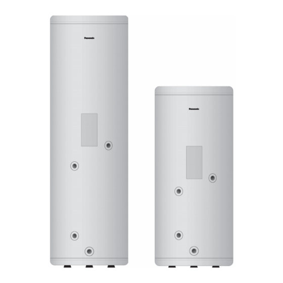
WH-TD20E3E5
WH-TD30E3E5-1
© Panasonic Corporation 2013.
Advertisement
Table of Contents

Related Manuals for Panasonic WH-TD20E3E5


Summary of Contents for Panasonic WH-TD20E3E5
-
Page 1: Table Of Contents
PRECAUTION OF LOW TEMPERATURE In order to avoid frostbite, be assured of no refrigerant leakage during the installation or repairing of refrigerant circuit. TABLE OF CONTENTS WH-TD20E3E5-UK WH-TD30E3E5-UK ...15 1. Safety Precautions..........3 7. Operation Control..........20 2. Specification ............5 Safety Valve ..........20... - Page 2 10. Technical Data ..........23 10.1 Tank Thermistor .........23 11. Replacement Parts List........24 11.1 WH-TD20E3E5 WH-TD30E3E5-1.....24 12. Replacement Parts List........25 12.1 WH-TD20E3E5-UK WH-TD30E3E5-UK ...25...
-
Page 3: Safety Precautions
1. Safety Precautions Read the following “SAFETY PRECAUTIONS” carefully before installation of Domestic Hot Water Tank Unit (hereafter referred to as “Tank Unit”). Electrical works and water installation works must be done by licensed electrician and licensed water system installer respectively. - Page 4 CAUTION 1. Installation work. Three people are required to carry out the installation work. The weight of Tank Unit might cause injury if carried by one person. 2. Do not install Tank Unit at place where leakage of flammable gas may occur. In case gas leaks and accumulates at surrounding of the Tank unit, it may cause fire.
-
Page 5: Specification
2. Specification Model WH-TD20E3E5 WH-TD30E3E5-1 Phase, Hz Single, 50 Power Supply Connection inch Stainless Steel 5/4 (CW602N brass quality) Material Incoloy 825 Electric Element Capacity Btu/h 10243 kJ/h 10800 Material Stainless Steel F18MT / AISI 444 / DIN 1.4521 Pressure vessel... - Page 6 Sensor pocket inch 2 × 1/2 BSP Anode inch 3/4 BSP Temperature & Pressure inch 3/4 × 1/2 BSP valve Design pressure Design data Design temperature °C This T&P valve (TPR15) for WH-TD20E3E5-UK and WH-TD30E3E5-UK must be used 75°C and under.
-
Page 7: Features
3. Features A hot water storage tank with capacity of 300Litres and 200Litres High Efficiency High Durable Made of clean stainless steel, the tank is designed to provide long lasting durability and toughness and exceptional resistance to rust. ... -
Page 8: Tank Dimensions & Components
4. Tank Dimensions & Components WH-TD20E3E5 WH-TD30E3E5-1 Unit: mm 1,8m 1,4m WH-TD20E3E5 WH-TD30E3E5-1 Main Components 1. Hot water outlet – 19.05 mm (3/4"BSP) 2. Electrical box lid 3. Sensor socket – 12.70 mm (1/2"BSP) 4. Flow inlet – 19.05 mm (3/4"BSP) 5. -
Page 9: Wh-Td20E3E5-Uk Wh-Td30E3E5-Uk
WH-TD20E3E5-UK WH-TD30E3E5-UK Unit: mm 1,8m 1,4m WH-TD20E3E5-UK WH-TD30E3E5-UK Main Components T & P Valve Dimension 1. Hot water outlet – 19.05 mm (3/4"BSP) 2. Electrical box lid 3. Sensor socket – 12.70 mm (1/2"BSP) 4. Flow inlet – 19.05 mm (3/4"BSP) 5. -
Page 10: Water Cycle Diagram
5. Water Cycle Diagram Connection for WH-SDH series or equivalent. Connection for WH-SDF / SDC series or equivalent. -
Page 11: Installation Instruction
6. Installation Instruction WH-TD20E3E5 WH-TD30E3E5-1 Dimension (mm) Capacity Model (Litre) Height Diameter WH-TD20E3E5 1150 WH-TD30E3E5-1 1600 Main components 1. Hot water outlet – 19.05 mm (3/4"BSP) 2. Electrical box lid 3. Sensor socket – 12.70 mm (1/2"BSP) 4. Flow inlet – 19.05 mm (3/4"BSP) 5. - Page 12 WARNING This section is for authorized and licensed electrician / water system installer only. Be sure to switch off all power supply (Tank Unit power supply, indoor unit power supply, heater power supply etc.) before performing installation. Install adjustable legs at bottom of tank (3 locations) then adjust the height until the unit stable. Fix the anode bar into socket.
- Page 13 6.1.1.1 Wiring at Tank Unit (Electrical box) WH-S*H MODELS WH-S*F / WH-S*C / WH-M*F / WH-M*C MODELS Cap tire cable (2.5 mm × 5 cable) Earth BOOSTER HEATER Earth 14 13 Cap tire cable (2.5 mm × 3 wires) BOOSTER TANK HEATER Must not change the volume knob.
- Page 14 6.1.2 Charge the Water WARNING Make sure Tank Unit filled up with water before switch on the power. 1) Make sure all the piping installations are properly done. 2) Set the water supply valve “OPEN” and all hot water tap “OPEN”. 3) Start filling water to the Tank Unit.
-
Page 15: Wh-Td20E3E5-Uk Wh-Td30E3E5-Uk
WH-TD20E3E5-UK WH-TD30E3E5-UK Dimension (mm) Weight (kg) Capacity Model Height Diameter Empty Full WH-TD20E3E5-UK 1150 WH-TD30E3E5-UK 1600 Main components 1. Hot water outlet – 19.05 mm (3/4"BSP) 2. Electrical box lid 8 10 3. Sensor socket – 12.70 mm (1/2"BSP) 4. Flow inlet – 19.05 mm (3/4"BSP) 5. - Page 16 Positioning the unit The water heater should be fitted level on a hard surface with sufficient load strength to take the full weight of cylinder. Adjustable feet are fitted to ensure the unit can be adjusted to a level position. There is no limitations regarding the fitting distance from walls etc., but it is strongly recommended to ensure easy access to all pipe fitting etc.
- Page 17 6.2.1.1 Wiring at Tank Unit (Electrical box) We are following UK Regulation KIWA Guidance. The tank is only for connection to Panasonic heat pumps in below model list. WH-SxFxxxxxx WH-SxCxxxxxx Cap tire cable WH-MxFxxxxxx (2.5 mm × 5 cable) WH-MxCxxxxxx...
- Page 18 6.2.2 Charge the Water WARNING Make sure Tank Unit filled up with water before switch on the power. 1) Make sure all the piping installations are properly done. 2) Set the water supply valve “OPEN” and all hot water tap “OPEN”. 3) Start filling water to the Tank Unit.
- Page 19 Temp./pressure Safety valve Exp. Vessel Product code pressure CW feed & coil Primary heater Relief valve Pressure/conn. pre charge WH-TD20E3E5-UK 8bar CW in 2bar, coil 2bar 0.09bar 90 - 95°C/10bar 8bar/15mm-1/2" 3.5bar WH-TD30E3E5-UK 8bar CW in 2bar, coil 2bar 0.11bar 90 - 95°C/10bar...
-
Page 20: Operation Control
7. Operation Control Safety Valve Use commercial T-joint to joint connection (D) of safety valve. Please install between water supply inlet and water supply tube at below of front side of Safety valve main unit. Please connect discharge drain at connector (R). Drain connection water During boiling, when pressure is above 9bar, discharge (3/4"BSP) -
Page 21: Troubleshooting Guide
8. Troubleshooting Guide Type of failure Possible cause Diagnostic and what to do Check if there is any power on the No power supply to the water power supply terminal on the Heater. No hot water thermostat. The fuse or safety cut-off to operate. Press the reset button. -
Page 22: Disassembly Instructions
9. Disassembly Instructions Replacing the Heating Element 1. Disconnect the power cable. 2. Remove the electric box lid (1). 3. Open Safety Relief valve (2) for a few seconds to relieve some of the pressure. This is done by turning knob counter-clockwise. Close the valve by turning the knob fully counter-clockwise until snaps shut. -
Page 23: Technical Data
10. Technical Data 10.1 Tank Thermistor Minimum Standard Maximum Temperature (°C) -
Page 24: Replacement Parts List
11. Replacement Parts List 11.1 WH-TD20E3E5 WH-TD30E3E5-1 SAFETY REF. NO. PART NAME & DESCRIPTION WH-TD20E3E5 WH-TD30E3E5-1 REMARK ANODE 26200 26250 ELECTRIC BOX LID 74050 ← THERMOSTAT KIT 80060 ← 5/4" HEATING ELEMENT 1 × 240V 71257 ← THERMISTOR POCKET 81020 ←... -
Page 25: Replacement Parts List
12. Replacement Parts List 12.1 WH-TD20E3E5-UK WH-TD30E3E5-UK SAFETY REF. NO. PART NAME & DESCRIPTION WH-TD20E3E5-UK WH-TD30E3E5-UK REMARK ANODE 56200 56250 ELECTRIC BOX LID 74050 ← THERMOSTAT KIT 80011 ← 5/4" HEATING ELEMENT 1 × 240V 71257 ← THERMISTOR POCKET 81020 ←...