Table of Contents
Advertisement
Service
Manual
AUDIO SYSTEM
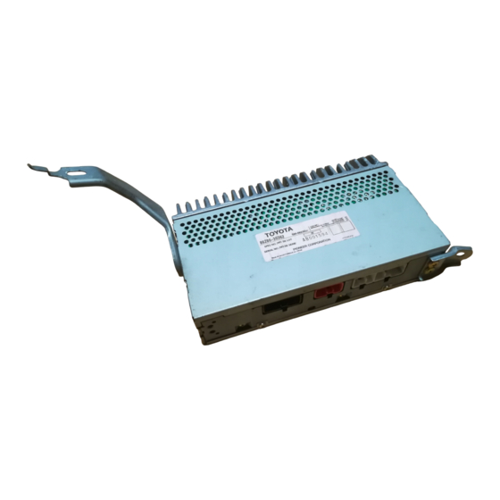
POWER AMPLIFIER
VEHICLE
DESTINATION
LEXUS GS300,430
USA,EUROPE
Manufactured for TOYOTA
by PIONEER CORPORATION
GS300,430
PRODUCED AFTER
TOYOTA PART No.
August 2000
86280-30372
86280-30362
ORDER NO.
CRT2497
ID No.
PIONEER MODEL No.
GM-8506ZT/E
GM-8506ZT-91/E
GM-8606ZT/E
GM-8606ZT-91/E
CRT2497
PUB. NO.
Advertisement
Table of Contents

Related Manuals for Pioneer GS300


Summary of Contents for Pioneer GS300
-
Page 1: Service Manual
Manual ORDER NO. CRT2497 GS300,430 AUDIO SYSTEM POWER AMPLIFIER VEHICLE DESTINATION PRODUCED AFTER TOYOTA PART No. ID No. PIONEER MODEL No. LEXUS GS300,430 USA,EUROPE August 2000 86280-30372 GM-8506ZT/E GM-8506ZT-91/E 86280-30362 GM-8606ZT/E GM-8606ZT-91/E Manufactured for TOYOTA CRT2497 by PIONEER CORPORATION PUB. NO. -
Page 2: Table Of Contents
GM-8506ZT,8506ZT-91,8606ZT,8606ZT-91 GM-8606ZT/E GM-8506ZT/E NOTE: - The GM-8506ZT-91/E and GM-8606ZT-91/E are supplementally genuine part for a TOYOTA vehicle, and a Pioneer product for recycling stock. - As for the structure and electrical system, there is no difference between the GM-8506ZT-91/E, GM-8606ZT-91/E and GM-8506ZT/E, GM-8606ZT/E. -
Page 3: Exploded Views And Parts List
GM-8506ZT,8506ZT-91,8606ZT,8606ZT-91 2. EXPLODED VIEWS AND PARTS LIST 2.1 EXTERIOR (GM-8506ZT/E) NOTE: - Parts marked by “*”are generally unavailable because they are not in our Master Spare Parts List. ∇ mark on the product are used for disassembly. - Screws adjacent to - EXTERIOR SECTION PARTS LIST Mark No. - Page 4 GM-8506ZT,8506ZT-91,8606ZT,8606ZT-91 2.2 EXTERIOR (GM-8606ZT/E) - EXTERIOR SECTION PARTS LIST Mark No. Description Part No. Mark No. Description Part No. 1 Screw BMZ30P060FMC 16 Screw(M3x6) CBA1393 2 Screw BMZ50P060FMC 17 Bracket CNC6807 3 Screw(M3x5) CBA1327 18 Holder CNC6808 4 Chassis CNA1852 19 Connector(CN901) CKM1222 5 Case...
-
Page 5: Block Diagram And Schematic Diagram
GM-8506ZT,8506ZT-91,8606ZT,8606ZT-91 3. BLOCK DIAGRAM AND SCHEMATIC DIAGRAM 3.1 BLOCK DIAGRAM DSP UNIT AMP UNIT... -
Page 6: Schematic Diagram
GM-8506ZT,8506ZT-91,8606ZT,8606ZT-91 3.2 SCHEMATIC DIAGRAM Note: When ordering service parts, be sure to refer to “EXPLODED VIEWS AND PARTS LIST” or “ELECTRICAL PARTS LIST”. 4.9V 4.9V Large size SCH diagram Guide page 5.0V Detailed page 2.3V 4.9V 4.9V 3.4V 4.9V 3.5V 3.5V 7.9V 3.0V... - Page 7 GM-8506ZT,8506ZT-91,8606ZT,8606ZT-91 DSP UNIT 4.9V 4.3V 7.9V 7.9V 4.3V 4.3V 4.9V 2.5V 4.3V TAPE: -10.05dBs CD: -3.55dBs 2.5V 4.3V 5.0V 4.9V 4.9V 4.3V 4.3V 4.9V 4.3V 2.5V 4.9V 4.3V 4.3V 4.3V 4.9V 2.5V TAPE: +0.2dBs CD: +8.2dBs TUNER(EW): -7.8dBs TUNER(UC):-12.8dBs 13.2V 12.7V 13.2V 0.3mH...
- Page 8 GM-8506ZT,8506ZT-91,8606ZT,8606ZT-91...
- Page 9 GM-8506ZT,8506ZT-91,8606ZT,8606ZT-91 A-a B...
- Page 10 GM-8506ZT,8506ZT-91,8606ZT,8606ZT-91...
- Page 11 GM-8506ZT,8506ZT-91,8606ZT,8606ZT-91 A-b B...
-
Page 12: Pcb Connection Diagram
GM-8506ZT,8506ZT-91,8606ZT,8606ZT-91 4. PCB CONNECTION DIAGRAM 4.1 DSP UNIT NOTE FOR PCB DIAGRAMS 1. The parts mounted on this PCB 2. Viewpoint of PCB diagrams include all necessary parts for several destination. Capacitor Connector For further information for SIDE A respective destinations, be sure to check with the schematic dia- gram. - Page 13 GM-8506ZT,8506ZT-91,8606ZT,8606ZT-91 SIDE A CN905...
- Page 14 GM-8506ZT,8506ZT-91,8606ZT,8606ZT-91 DSP UNIT...
- Page 15 GM-8506ZT,8506ZT-91,8606ZT,8606ZT-91 SIDE B...
- Page 16 GM-8506ZT,8506ZT-91,8606ZT,8606ZT-91 4.2 AMP UNIT AMP UNIT CN51...
- Page 17 GM-8506ZT,8506ZT-91,8606ZT,8606ZT-91 SIDE A CN52...
- Page 18 GM-8506ZT,8506ZT-91,8606ZT,8606ZT-91 AMP UNIT...
- Page 19 GM-8506ZT,8506ZT-91,8606ZT,8606ZT-91 SIDE B...
-
Page 20: Electrical Parts List
GM-8506ZT,8506ZT-91,8606ZT,8606ZT-91 5. ELECTRICAL PARTS LIST NOTE: - Parts whose parts numbers are omitted are subject to being not supplied. - The part numbers shown below indicate chip components. Chip Resistor RS1/_S___J,RS1/__S___J Chip Capacitor (except for CQS..) CKS.., CCS.., CSZS..=====Circuit Symbol and No.===Part Name Part No. - Page 21 GM-8506ZT,8506ZT-91,8606ZT,8606ZT-91 =====Circuit Symbol and No.===Part Name Part No. =====Circuit Symbol and No.===Part Name Part No. ------ ------------------------------------------ ------------------------- ------ ------------------------------------------ ------------------------- (GM-8606ZT/E) RS1/10S473J RS1/10S472J RS1/10S102J RS1/10S682J RS1/10S102J RS1/10S103J RS1/10S102J RS1/10S154J RS1/10S473J RS1/10S472J RS1/10S104J RS1/10S473J RS1/10S473J RS1/10S392J RS1/10S102J RS1/10S103J RS1/10S473J RS1/10S102J RS1/10S473J RS1/10S473J RS1/10S393J...
-
Page 22: Amp Unit
GM-8506ZT,8506ZT-91,8606ZT,8606ZT-91 =====Circuit Symbol and No.===Part Name Part No. =====Circuit Symbol and No.===Part Name Part No. ------ ------------------------------------------ ------------------------- ------ ------------------------------------------ ------------------------- CKSQYB104K50 CEJA330M10 CKSQYB224K16 CEAL220M10 CEAL100M16 CEALNP100M10 CKSQYB103K50 CEALNP100M10 CKSQYB103K50 CKSQYB823K25 CEAL101M10 CEALNP220M16 CKSQYB104K50 CEALR68M50 CEALNP1R0M50 CEAL100M16 CEALNP1R0M50 CEJA470M10 CEALNP1R0M50 CEAL100M16 CEALNP1R0M50 CEALNP100M10... - Page 23 GM-8506ZT,8506ZT-91,8606ZT,8606ZT-91 =====Circuit Symbol and No.===Part Name Part No. =====Circuit Symbol and No.===Part Name Part No. ------ ------------------------------------------ ------------------------- ------ ------------------------------------------ ------------------------- Diode UDZ20(B) RS1/10S620J Diode UDZ20(B) RS1/10S302J Diode UDZ20(B) RS1/10S302J Choke Coil 0.3mA CTH1079 RS1/10S1R0J RS1/10S1R0J RESISTORS RS1/10S473J RS1/10S153J RS1/10S104J RS1/10S153J RS1/8S222J RS1/10S333J...
- Page 24 GM-8506ZT,8506ZT-91,8606ZT,8606ZT-91 =====Circuit Symbol and No.===Part Name Part No. =====Circuit Symbol and No.===Part Name Part No. ------ ------------------------------------------ ------------------------- ------ ------------------------------------------ ------------------------- CEJA100M16 CKSQYB102K50 CEJA2R2M50 CKSQYB102K50 CEANLR47M50 CKSQYB102K50 CEANLR47M50 CKSQYB102K50 CEANL4R7M50 CKSQYB102K50 CEANL4R7M50 CKSQYB102K50 CKSQYB102K50 CKSQYB102K50 CFTNA154J50 CFTNA154J50 CFTNA154J50 CFTNA154J50 CEAS221M16 1µF/50V CCH1296 1µF/50V...
-
Page 25: Adjustment
GM-8506ZT,8506ZT-91,8606ZT,8606ZT-91 6. ADJUSTMENT - Connection Diagram KEX-M8506ZT/UC KEX-M9506ZT/UC KEX-M8606ZT/EW Display KEX-M8706ZT/EW GGD1236 DSP AMP GM-8506ZT/E GM-8606ZT/E GGD1167 GGD1144 GGD1148 CD Changer CDX-M8076ZT/E... - Page 26 GM-8506ZT,8506ZT-91,8606ZT,8606ZT-91 KEX-M8406ZT/UC KEX-M9406ZT/UC KEX-M9006ZT/EW KEX-M9106ZT/EW GGD1236 DSP AMP GM-8506ZT/E GM-8606ZT/E GGD1167 GGD1144 CD Changer GGD1148 CDX-M8076ZT/E CDX-M8106ZT/E...
- Page 27 GM-8506ZT,8506ZT-91,8606ZT,8606ZT-91 - Jig GGD1153...
- Page 28 GM-8506ZT,8506ZT-91,8606ZT,8606ZT-91 ASL SECTION Preset conditions 1. Set VR601 and VR602 around the center of the adjustable range. 2. Ground pins 3 and 16 of IC601. Step Input Output Adjustment (MIC) (Pin 22) Adj.point Spec. Conditions By using an oscillator, apply a sine Observe the output at VR602 1.2±0.3V...
-
Page 29: General Information
GM-8506ZT,8506ZT-91,8606ZT,8606ZT-91 7. GENERAL INFORMATION 7.1 DIAGNOSIS 7.1.1 DISASSEMBLY Case Removing the Case(Fig.1) Heat Sink 1. Remove the Seal marked with arrows. 2. Remove the seven screws A, seven screws B, and then remove the Case and Heat Sink. Fig. 1 Shield Removing the DSP Unit(Fig.2) 1. -
Page 30: Connector Function Description
GM-8506ZT,8506ZT-91,8606ZT,8606ZT-91 7.1.2 CONNECTOR FUNCTION DESCRIPTION SFL+ SFR+ SRL+ SRR+ TLMT GND SRR- SRL- N-MU SFL- SFR- CDR+ TXM+ CDL+ CDL- SGND CDMT CDR- TXM- MUTE SGND BUS+ BUS-... - Page 31 GM-8506ZT,8506ZT-91,8606ZT,8606ZT-91 7.2 IC PD2055A...
- Page 32 GM-8506ZT,8506ZT-91,8606ZT,8606ZT-91 - Pin Functions (PD5584B) Pin No. Pin Name Format Function and Operation ASLIN Difference of noise and signal input TLMT TEL mute input AVCIN AVC-LAN data input AVCOUT AVC-LAN data output AVCPW AVC-LAN driver power supply output DSPACK DSP-IC ACK input DSPCK DSP serial clock output DSPDT...
-
Page 33: Explanation
GM-8506ZT,8506ZT-91,8606ZT,8606ZT-91 7.3 EXPLANATION 7.3.1 OPERATIONAL FLOW CHART Reset Start---OFF ---Power ON START | Hard ware reset cancel <<JUDGMENT>> TESTIN LOW input Test program check(Unit checker) - TESTIN HI/LOW input ASENS LOW input BSENS LOW input TESTIN HI input ASENS HI input BSENS HI input Unit checker program <<JUDGMENT>>... - Page 34 GM-8506ZT,8506ZT-91,8606ZT,8606ZT-91 - DSP error check (Normal) DSPERR1 DSPERR2 Both terminals confirmation every 4mS DSPCS1 DSPCS2 DSPCK 4mS interval (Periodical communication) DSPCS1 DSPCS2 DSPCK - Electronic volume refresh (Normal) Electronic VR IF About 500mS interval VCK1 VCK2 - DSP error check ---Error continuation DSPRST About 1S interval...
-
Page 35: System Block Diagram
GM-8506ZT,8506ZT-91,8606ZT,8606ZT-91 7.3.2 SYSTEM BLOCK DIAGRAM POWER SUPPLY(+B, ACC) SIGNAL(SOUND, VISION) - NAVIGATION SYSTEM(7SP) +B, ACC GM-8506ZT/E GM-8606ZT/E +B, ACC KEX-M8506ZT/UC KEX-M8606ZT/EW KEX-M8706ZT/EW VISION NAVIGATION (OTHER MAKERS) CDX-M8076ZT/E (OTHER MAKERS) CDX-M8176ZT/E +B, ACC - (7SP) +B, ACC GM-8506ZT/E GM-8606ZT/E +B, ACC KEX-M8406ZT/UC KEX-M9006ZT/EW KEX-M9106ZT/EW... -
Page 36: Service Mode For Dsp Amplifier
GM-8506ZT,8506ZT-91,8606ZT,8606ZT-91 7.3.3 Service Mode For DSP Amplifier 1. Outline This specifications details operation according to our suggestion for answering complaint about sound quality in audio systems. It is based on an assump- tion that a dealer or service person operate the prod- uct to solve the problem. - Page 37 GM-8506ZT,8506ZT-91,8606ZT,8606ZT-91 Sound Quality Service mode Displaying "AUDIO" FM1/2 TAPE Displaying "P1 XXX" Displaying "F XX" FM1/2 TAPE Displaying "P2 XXX" Displaying "R XX" FM1/2 TAPE Displaying "L XX" Displaying "W XX" FM1/2 TAPE Frequency characteristics Level adjustment function adjustment function Flowchart of displays in Sound Quality Adjustment mode...
- Page 38 GM-8506ZT,8506ZT-91,8606ZT,8606ZT-91 5. Details 1 Frequency characteristics adjustment function 2 level adjustment function • The system changes submodes cyclically every • The system changes submodes cyclically every time the [FM1/2] button is pressed when time the [TAPE] button is pressed when "AUDIO" "AUDIO"...
-
Page 39: Specifications
GM-8506ZT,8506ZT-91,8606ZT,8606ZT-91 8. SPECIFICATIONS Power source ... . .13.2±0.1V(10.5-16.0V) Grounding ....NEGATIVE TYPE Electrode dark current ..1mA or less(13.2V) Dimensions (No bracket) . - Page 40 GM-8506ZT,8506ZT-91,8606ZT,8606ZT-91 PIONEER CORPORATION 4-1, Meguro 1-Chome, Meguro-ku, Tokyo 153-8654, Japan PIONEER ELECTRONICS SERVICE INC. P.O.Box 1760, Long Beach, CA 90801-1760 U.S.A. PIONEER EUROPE NV Haven 1087 Keetberglaan 1, 9120 Melsele, Belgium PIONEER ELECTRONICS ASIACENTRE PTE.LTD. 253 Alexandra Road, #04-01, Singapore 159936 C PIONEER CORPORATION 2000 K-ZZB.