Table of Contents
Advertisement
SERVICE MANUAL
TECHNICAL INFORMATION
FOR SERVICE PERSONNEL ONLY
SPECIFICATIONS
TYPE
MODEL
POWER SOURCE
TOTAL INPUT
TOTAL AMPERES
COOLING
CAPACITY
TOTAL INPUT
TOTAL AMPERES
HEATING
CAPACITY
DIMENSIONS (mm)
NET WEIGHT (kg)
SPECIFICATIONS AND PARTS ARE SUBJECT TO CHANGE FOR IMPROVEMENT
ROOM AIR CONDITIONER
MARCH 2004
RAC-07CH4
RAC-09CH4
INDOOR UNIT
RAS-07CH4
(W)
(A)
(kW)
(B.T.U./h)
(W)
(A)
(kW)
(B.T.U./h)
W
785
H
265
D
168
7
INDOOR UNIT + OUTDOOR UNIT
PM
RAS-07CH4/RAC-07CH4
RAS-09CH4/RAC-09CH4
REFER TO THE FOUNDATION MANUAL
SPECIFICATIONS ............................................................... 5
HOW TO USE ..................................................................... 6
CONSTRUCTION AND DIMENSIONAL DIAGRAM ........ 32
MAIN PARTS COMPONENTS ......................................... 33
WIRING DIAGRAM ........................................................... 35
BASIC MODE .................................................................... 41
REFRIGERATING CYCLE ................................................ 46
AUTO SWING FUNCTION ............................................... 47
PARTS LIST AND DIAGRAM ........................................... 53
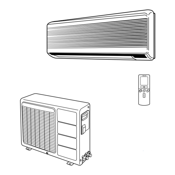
WALL TYPE
OUTDOOR UNIT
INDOOR UNIT
RAC-07CH4
RAS-09CH4
1Ø, 220 V, 50 Hz
680
3.15
2.05
7,000
630
3.0
2.15
7,850
700
570
210
26
NO. 0205E
CONTENTS
OUTDOOR UNIT
RAC-09CH4
870
4.1
2.50
8,500
860
4.1
2.65
10,000
785
700
265
570
168
210
7
26
H.A.P.M.
Advertisement
Table of Contents

Related Manuals for Hitachi RAS-07CH4


Summary of Contents for Hitachi RAS-07CH4
-
Page 1: Table Of Contents
NO. 0205E RAS-07CH4/RAC-07CH4 RAS-09CH4/RAC-09CH4 SERVICE MANUAL REFER TO THE FOUNDATION MANUAL TECHNICAL INFORMATION FOR SERVICE PERSONNEL ONLY CONTENTS SPECIFICATIONS ............... 5 HOW TO USE ..............6 CONSTRUCTION AND DIMENSIONAL DIAGRAM ..32 MAIN PARTS COMPONENTS ......... 33 WIRING DIAGRAM ............35 RAS-07CH4 BASIC MODE .............. - Page 2 SAFETY DURING REPAIR WORK 1. In order to disassemble and repair the unit in question, be sure to disconnect the power cord plug from the power outlet before starting the work. 2. If it is necessary to replace any parts, they should be replaced with respective genuine parts for the unit, and the replacement must be effected in correct manner according to the instructions in the Service Manual of the unit.
- Page 3 WORKING STANDARDS FOR PREVENTING BREAKAGE OF SEMICONDUCTORS 1. Scope The standards provide for items to be generally observed in carrying and handling semiconductors in relative manufacturers during maintenance and handling thereof. (They apply the same to handling of abnormal goods such as rejected goods being returned).
- Page 4 (6) Use a three wire type soldering iron including a grounding wire. Metal plate (of aluminium, stainless steel, etc.) Working table Resistor of 1 MΩ (1/2W) Staple Earth wire Bare copper wire (for body earth) Fig. 3. Grounding of the working table Soldering iron Grounding wire Screw stop at the screwed...
- Page 5 CAUTION 1. In quiet or stop operation, slight flowing noise of refrigerant in the refrigerating cycle is heard occasionally, but this noise is not abnormal for the operation. 2. When it thunders near by, it is recommend to stop the operation and to disconnect the power cord plug from the power outlet for safety.
- Page 6 The Length of Indoor Unit Connecting Cord about about 1.6m 0.9m Figure showing the Installation Do not alter the power cord. of Indoor and Outdoor unit. Cut away shaded portion, and finish the edge of the opening so that there is no burr. above 50mm Be sure to completely...
-
Page 7: Ras-07Ch4
SPECIFICATIONS MODEL RAS-07CH4 RAC-07CH4 RAS-09CH4 RAC-09CH4 FAN MOTOR 10 W 20 W 10 W 20 W FAN MOTOR CAPACITOR 1 µF, 400 V 1.5 µF, 400 V 1 µF, 400 V 1.5 µF, 400 V FAN MOTOR PROTECTOR YES (INTERNAL) YES (INTERNAL) YES (INTERNAL) YES (INTERNAL) -
Page 8: Safety Precaution
SAFETY PRECAUTION Please read the “Safety Precaution” carefully before operating the unit to ensure correct usage of the unit. Pay special attention to signs of “ Warning” and “ Caution”. The “Warning” section contains matters which, if not observed strictly, may cause death or serious injury. The “Caution” section contains matters which may result in serious consequences if not observed properly. - Page 9 PRECAUTIONS DURING OPERATION The product shall be operated under the manufacturer specification and not for any other intended use. Do not attempt to operate the unit with wet hands, this could cause fatal accident. When operating the unit with burning equipments, regularly ventilate the room to avoid oxygen insufficiency.
-
Page 10: Names And Functions Of Each Part
OUTDOOR UNIT Drain pipe Condensed water drain to outside. Connecting cord Air inlet (Back and left side) Air outlet Blow out warm air. MODEL NAME AND DIMENSIONS MODEL WIDTH (mm) HEIGHT (mm) DEPTH (mm) RAS-07CH4, RAS-09CH4 RAC-07CH4, RAC-09CH4 – 8 –... -
Page 11: Indoor Unit Indicators
OPERATION INDICATOR TEMPORARY SWITCH Temporary Switch about 7mm Press Non-conductor Stick Use this switch to start and stop when the remote controller does not work. [Use non-conductor stick (example toothpick)] RAS- By pressing the temporary switch, the operation is done in previously set operation mode. -
Page 12: Names And Functions Of Remote Control Unit
NAMES AND FUNCTIONS OF REMOTE CONTROL UNIT REMOTE CONTROLLER This controls the operation of the indoor unit. The range of control is about 7 meters. If indoor lighting is controlled electronically, the range of control may be shorter. This unit can be fixed on a wall using the fixture provided. Before fixing it, make sure the indoor unit can be controlled from the remote controller. -
Page 13: Automatic Operation
AUTOMATIC OPERATION The device will automatically determine the mode of operation, HEAT, COOL or DEHUMIDIFY depending on the initial room temperature. The selected mode of operation will not change when the room temperature varies. Press the FUNCTION selector so that the display indicates the (AUTO) mode of operation. -
Page 14: Heating Operation
HEATING OPERATION Use the device for heating when the outdoor temperature is under 21°C. When it is too warm (over 21°C), the heating function may not work in order to protect the device. Press the FUNCTION selector so that the display indicates the (HEAT). -
Page 15: Dehumidifying Operation
DEHUMIDIFYING OPERATION Use the device for dehumidifying when the room temperature is over 16°C. When it is under 15°C, the dehumidifying function will not work. ˚ Press the FUNCTION selector so that the display indicates (DEHUMIDIFY). The FAN SPEED is set at LOW automatically. The FAN SPEED button does not work. -
Page 16: Cooling Operation
COOLING OPERATION Use the device for cooling when the outdoor temperature is 22-42°C. If humidity is very high (over 80%) indoors, some dew may form on the air outlet grille of the indoor unit. Press the FUNCTION selector so that the display indicates the (COOL). -
Page 17: Fan Operation
FAN OPERATION You can use the device simply as an air circulator. Use this function to dry the interior of the indoor unit at the end of summer. Press the FUNCTION selector so that the display indicates the (FAN). Press the (FAN SPEED) button. -
Page 18: How To Set The Timer
HOW TO SET THE TIMER Time, Day, Month Set the current month and TIME, DAY, day with the TIMER control After you change the MONTH button. batteries; (current time, day, month) OFF TIMER RESET ON TIMER OFF-Timer Press the (OFF-TIMER) button. - Page 19 Press the Set the current time with Press the (TIME) button again. (TIME) button. the TIMER control button. The time indication starts lighting instead of flashing. The time indication will disappear automatically in 10 second. To check the current time setting, press the (TIME) button twice.
-
Page 20: How To Set The Sleep Timer
HOW TO SET THE SLEEP TIMER Set the current time at first if it is not set before (see the pages for setting the current time). Press the (SLEEP) button, and the display changes as shown below. Mode Indication 1 hour 2 hours 3 hours 7 hours... - Page 21 Explanation of the sleep timer The device will control the FAN SPEED and room temperature automatically so as to be quiet and good for people’s health. You can set the sleep timer to turn off after 1, 2, 3 or 7 hours. The FAN SPEED and room temperature will be controlled as shown below.
-
Page 22: Adjusting The Air Deflectors
ADJUSTING THE AIR DEFLECTORS Adjustment of the conditioned air in the upward and downward directions. According to “Dehumidifying” and “Cooling” operation, the horizontal air deflector is automatically set to the proper angle suitable for each operation. The deflector can be swung up and down and also set to the desired angle using the “... -
Page 23: How To Exchange The Batteries In The Remote Controller
HOW TO EXCHANGE THE BATTERIES IN THE REMOTE CONTROLLER Remove the cover as shown in the figure and take out the old batteries. Push and pull to the direction of arrow Install the new batteries. The direction of the batteries should match the marks in the case. - Page 24 THE IDEAL WAYS OF OPERATION Suitable Room Temperature Install curtain or blinds Warning It is possible to Freezing temperature is reduce heat bad for health and a entering waste of electric power. room through windows. Ventilation Effective Usage Of Timer At night, please use the “OFF or ON timer Caution operation mode”, together with your wake up...
- Page 25 FOR USER’S INFORMATION The Air Conditioner And The Heat Source In The Room Caution If the amount of heat in the room is above the cooling capability of the air conditioner (for example: more people entering the room, using heating equipments and etc.), the preset room temperature cannot be achieved.
- Page 26 MAINTENANCE CAUTION Before the cleaning, stop operation and disconnect the power supply. 1. AIR FILTER Clean the air filter, as it removes dust inside the room. In case the air filter is full of dust, the air flow will decrease and the cooling capacity will be reduced. Further, noise may occur. Be sure to clean the filter following the procedure below.
- Page 27 3. MAINTENANCE AT BEGINNING OF LONG OFF PERIOD Running the unit setting the operation mode to (FAN) and the fan speed to HI for about half a day on a fine day, and dry the whole of the unit. Disconnect the power plug. Blow REGULAR INSPECTION PLEASE CHECK THE FOLLOWING POINTS EVERY EITHER HALF YEARLY...
- Page 28 AFTER SALES SERVICE AND WARRANTY WHEN ASKING FOR SERVICE, CHECK THE FOLLOWING POINTS. CONDITION CHECK THE FOLLOWING POINTS Is the fuse all right? When it does not operate Is the voltage extremely high or low? Is the circuit breaker “ON”? Was the air filter cleaned? Does sunlight fall directly on the outdoor unit? Is the air flow of the outdoor unit obstructed?
- Page 29 HOW TO REPLACE NEW UV-LED AND FILTER Open the front cover. Cut the binder. Lift up the left side of the evaporator. – 27 –...
- Page 30 Rear view Remove tape at the Remove aluminium tape Remove tape at the cabinet. at the cabinet. electrical box. Disconnect the connector between UV-LED and electrical box. Remove the K-spring. Pull up the ACL-holder. – 28 –...
- Page 31 Remove the UV-LED. If necessary, change the ACL filter (SPX-CFH9). After replace new UV-LED and filter, make sure to reattach the aluminium tape. Put back the K-spring. Connect the connector between UV- LED and electrical box. – 29 –...
- Page 32 Rear view Reattach tape at the Reattach tape at the cabinet. electrical box. Reattach the evaporator to its place. Reattach the binder. – 30 –...
- Page 33 Put back the front cover. – 31 –...
-
Page 34: Construction And Dimensional Diagram
CONSTRUCTION AND DIMENSIONAL DIAGRAM MODEL RAS-07CH4, RAS-09CH4 17.5 Wireless remote controller Wireless remote controller Front cover Top Air suction grill Mounting Air suction grill plate Cabinet Cabinet Discharge grill Horizontal air deflector Vertical air deflector Drain cap connection part (167.5) 167.5... -
Page 35: Main Parts Components
MAIN PARTS COMPONENTS THERMOSTAT Thermostat Specifications MODEL RAS-07CH4, RAS-09CH4 THERMOSTAT MODEL 17.6 (63.7) INDICATION 16.6 (61.8) TEMPERATURE 25.6 (78.1) INDICATION °C (°F) 24.6 (76.3) 33.6 (92.5) INDICATION 32.6 (90.7) FAN MOTOR Fan Motor Specifications RAS-07CH4, RAS-09CH4 RAC-07CH4, RAC-09CH4 MODEL PHASE... - Page 36 COMPRESSOR MOTOR Compressor Motor Specifications MODEL RAC-07CH4 RAC-09CH4 COMPRESSOR MODEL G333DB2Z G533QB9Z PHASE SINGLE SINGLE RATED VOLTAGE 220 – 240 V 220 – 240 V RATED FREQUENCY 50 Hz 50 Hz LOCKED ROTOR CURRENT 22 A 22 A POLE NUMBER WHITE ORANGE CONNECTION...
-
Page 37: Wiring Diagram
WIRING DIAGRAM MODEL RAS-07CH4, RAC-07CH4 COMPRESSOR : REVERSING VALVE : FAN MOTOR : POWER RELAY : POWER SWITCH : THERMAL FUSE FOR TERMINAL BOARD : 1,000 PF CAPACITOR : SURGE ASSORBER : FAN MOTOR PROTECTOR (INTERNAL) : THERMISTOR : 1 µF CAPACITOR : TRANSFORMER : 35 µF CAPACITOR... - Page 38 – 36 –...
- Page 39 MODEL RAS-07CH4, RAS-09CH4 RESISTOR SYMBOL RESISTANCE TOLERANCE POWER FORM RESISTANCE TOLERANCE POWER SYMBOL RESISTANCE TOLERANCE POWER FORM SYMBOL FORM ±5% ±5% ±5% 1/16W R201 1/10W R401 1/16W R601 ±5% ±5% ±5% R202 1/16W R402 1/16W R603 1/16W ±5% ±5% ±5%...
- Page 40 R901 UV LED MODEL RAS-07CH4, RAS-09CH4 BOARD HP BOARD TERMINAL POWER BOARD LINE CORD POWER RELAY SWITCH (BROWN) BROWN AC240V (BLUE) BLUE 50Hz (YELLOW/ BLACK GREEN) WHITE OUTDOOR FAN RELAY SSR-H REVERSING VALVE RELAY CN11 SSR-L (XH-6P) WHITE SSR-S (HIGH)
-
Page 41: Basic Mode
BASIC MODE Operation mode Cooling Sensor dehumidification Heating Automatic Control function Start/stop button, Start/stop button Operation and stop are repeated TEMPERATURE OF INDOOR HEAT basic mode operation lamp independent of timer reservations EXCHANGER THERMISTOR Start/stop button Reservation Cancel OFF timer Operation lamp Timer lamp Timer memory... - Page 42 Operation mode Cooling Sensor dehumidification Heating Automatic Control function "Strong" circulation 15sec 30 sec 30 sec 30 sec 30 sec • At the time of heating Other detailed specifications operation mode, the same Start/stop switch Table 1 Specifications operation as for heating is Thermostat signal 1.
- Page 43 Timer-Lamp, break-down checking in blinking sign. Check the break-down factor from the frequency of timer-lamp blinking. Mode of Timer-Lamp blinking Indication Factor Estimated Break-Down Part Forced cool operation (1) Service switch at Indoor has been set to “COOL” position. Running force-cool operation by (2) Control P.W.B.
-
Page 44: Refrigeration Cycle
REFRIGERATION CYCLE COOLING DEFROST ø6.35 Outdoor Unit Indoor Unit Suction Cooling Tank Reversing Defrost Comp Valve Service Valve Union (3/8) (3/8) 9.52 9.52 11.0 9.52 6.35 9.52 6.35 Service Valve (1/4) 6.35 6.35 Union 6.35 Strainer (1/4) Capillary 6.35 6.35 4.76 Strainer Charging Pipe... - Page 45 – 47 –...
-
Page 46: Service Call Q & A
SERVICE CALL Q & A Cooling operation Check whether frost sticks on If cooling is performance While cooling, the com- the heat exchanger of unit or when the room tem- pressor sometimes stops not. perature is low, frost may abruptly. Wait for 3 - 4 minutes until the stick on the heat exchanger frost melts. - Page 47 Heating operation It is not a trouble. The fan is When starting the operation, Air does not come out when stopped to avoid cold wind. the heat exchanger is cold starting a heating operation. and, therefore, the fan is stopped. Wait 2–3 minutes.
- Page 48 Automatic operation How is the automatic According to the room operation mode determined? temperature, cooling, heating or dehumidifying operation automatically selected. Cooling: When room temperature is approx. 27°C or higher. Dehumidifying: When room temperature is between approx. 23°C and 27°C. Heating: When room temperature is approx.
- Page 49 Common, etc. There is a difference There may be a difference between room between room temperature setting and temperature setting and actual room temperature. actual room temperature on account room structure, air flow, etc. If there is a difference, adjust the set temperature to keep living space at a comfortable temperature.
- Page 50 Wireless remote controller When the room temperature The room temperature os setting is “16”, pressing the settable within the range of room temperature control 16 - 32 and not beyond. button “ V ” causes no transmission. “32”, pressing “ ”...
-
Page 51: Parts List And Diagram
PARTS LIST AND DIAGRAM MODEL RAS-07CH4, RAS-09CH4 – 53 –... - Page 52 MODEL RAS-07CH4 PART NO. Q’TY / UNIT PARTS NAME RAS-07CH4 PMRAS-07CH4 CABINET PMRAS-07CH4 LOW-COVER PMRAS-07CH2 10W MOTOR PMRAS-09C1 TANGENTIAL FLOW FAN PMRAS-05C P-BEARING ASSEMBLY PMRAS-05C BEARING COVER PMRAS-26CHAI FAN MOTOR SUPPORT PMRAS-07CH4 DRAIN PAN ASSEMBLY PMRAS-07CH4 FRONT COVER ASSEMBLY PMRAS-05C...
- Page 53 MODEL RAS-09CH4 PART NO. Q’TY / UNIT PARTS NAME RAS-09CH4 PMRAS-07CH4 CABINET PMRAS-07CH4 LOW-COVER PMRAS-07CH2 10W MOTOR PMRAS-09C1 TANGENTIAL FLOW FAN PMRAS-05C P-BEARING ASSEMBLY PMRAS-05C BEARING COVER PMRAS-26CHAI FAN MOTOR SUPPORT PMRAS-07CH4 DRAIN PAN ASSEMBLY PMRAS-07CH4 FRONT COVER ASSEMBLY PMRAS-05C MOUNTING PLATE PMRAS-07CH4 REMOTE CONTROL...
- Page 54 MODEL RAC-07CH4, RAC-09CH4 – 56 –...
- Page 55 MODEL RAC-07CH4 PART NO. Q’TY / UNIT PARTS NAME RAC-07CH4 PMRAC-07CH2 OVERLOAD PROTECTOR RA-226 O.L.R. COVER RA-226 COVER SUPPORT PMRAC-05CV FAN MOTOR SUPPORT PMRAC-07G1 FAN MOTOR 20W PMRAC-05CV PROPELLER FAN PMRAC-07CH2 CABINET PMRAC-07CH2 ELECTRICAL COVER ASSEMBLY PMRAC-05CV SIDE PLATE (R) PMRAC-05CV SIDE PLATE (L) PMRAC-05CV...
- Page 56 MODEL RAC-09CH4 PART NO. Q’TY / UNIT PARTS NAME RAC-09CH4 PMRAC-09CH2 OVERLOAD PROTECTOR RA-226 O.L.R. COVER RA-226 COVER SUPPORT PMRAC-05CV FAN MOTOR SUPPORT PMRAC-07G1 FAN MOTOR 20W PMRAC-05CV PROPELLER FAN PMRAC-07CH2 CABINET PMRAC-07CH2 ELECTRICAL COVER ASSEMBLY PMRAC-05CV SIDE PLATE (R) PMRAC-05CV SIDE PLATE (L) PMRAC-05CV...
- Page 57 PM NO. 0205E RAS-07CH4 / RAC-07CH4 RAS-09CH4 / RAC-09CH4 Printed in Malaysia – 59 –...