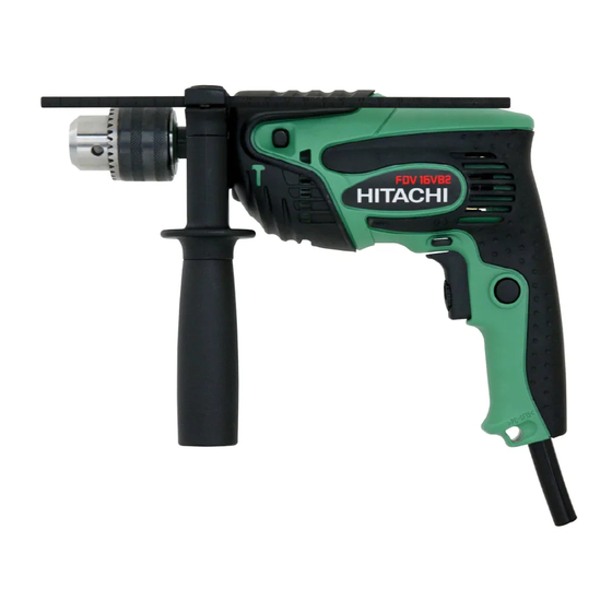
Hitachi FDV 16VB2 Technical Data And Service Manual
Impact drill
Hide thumbs
Also See for FDV 16VB2:
- Manual (82 pages) ,
- Instruction manual (44 pages) ,
- Handling instructions manual (44 pages)

Related Manuals for Hitachi FDV 16VB2


Summary of Contents for Hitachi FDV 16VB2
- Page 1 MODEL FDV 16VB2 Hitachi Power Tools TECHNICAL DATA IMPACT DRILL FDV 16VB2 SERVICE MANUAL LIST No. F895 Jan. 2004 SPECIFICATIONS AND PARTS ARE SUBJECT TO CHANGE FOR IMPROVEMENT...
- Page 2 REMARK: Throughout this TECHNICAL DATA AND SERVICE MANUAL, a symbol(s) is(are) used in the place of company name(s) and model name(s) of our competitor(s). The symbol(s) utilized here is(are) as follows: Competitors Symbols Utilized Company Name Model Name MAKITA HP1500 MAKITA HP1501...
-
Page 3: Table Of Contents
8-3. Lubrication ..........................12 8-4. Tightening Torque ........................12 8-5. Wiring Diagram and Lead Wire Arrangements ................13 8-6. Insulation Tests .......................... 16 8-7. No-Load Current Values ......................16 9. STANDARD REPAIR TIME (UNIT) SCHEDULES ..............17 Assembly Diagram for FDV 16VB2... -
Page 4: Product Name
Hitachi Impact Drill, Model FDV 16VB2 2. MARKETING OBJECTIVE The new Model FDV 16VB2 is the upgraded version of the previous Model FDV 16VB, developed under the concept for more convenient model. Thanks to the nonskid large soft grip and the push-button type forward/ reverse changeover switch, the Model FDV 16VB2 is easier to operate than the previous model. -
Page 5: Selling Point Descriptions
(2) Nonskid large soft grip Most of the conventional soft grips cover only the handle. The Model FDV 16VB2 is equipped with the nonskid grip that largely covers both the handle and the housing (drill chuck side) to prevent slipping even if the operator holds the Model FDV 16VB2 in various ways. - Page 6 (6) Easy-to-operate push-button type forward/reverse changeover switch The Model FDV 16VB2 is equipped with the push-button type forward/reverse changeover switch that is more convenient and reliable than the lever-type switch. In addition, this switch is properly shaped and located not to make the pushing button an obstruction at drilling.
-
Page 7: Specifications
5. SPECIFICATIONS 5-1. Specifications Capacities Masonry 16 mm (5/8") Steel 13 mm (1/2") Wood 25 mm (1") Drill chuck Type Keyless With chuck key Mount type UNF 1/2" --- 20 1.5 --- 13 mm (1/16" to 1/2") Capacity Power source AC single phase 50/60 Hz Current (A) Voltage (V) -
Page 8: Comparisons With Similar Products
6. COMPARISONS WITH SIMILAR PRODUCTS 6-1. Specification Comparisons HITACHI C-1/C-2 FDV 16VB2 FDV 16VB 16 (5/8") 16 (5/8") 15 (5/8") Capacity Masonry 13 (1/2") 13 (1/2") 13 (1/2") Steel 25 (1") 25 (1") Wood 25 (1") Type With key Keyless... -
Page 9: Drilling Speed Comparisons
The data shown below were obtained in actual factory tests, and are for reference only. Actual drilling speeds may vary in accordance with operating conditions, operator skill, etc. HITACHI HITACHI C-1, C-2 FDV 16VB FDV 16VB2 16 dia. 10 dia. 8 dia. 12 dia. 14.5 dia. -
Page 10: Precautions In Sales Promotion
7. PRECAUTIONS IN SALES PROMOTION In the interest of promoting the safest and most efficient use of the Model FDV 16VB2 Impact Drill by all of our customers, it is very important that at the time of sales the salesperson carefully ensures that the buyer seriously recognizes the importance of the contents of the Handling Instructions, and fully understands the meaning of the precautions listed on the Caution Plate attached to each tool. - Page 11 (2) Speed control switch The switch allows adjustment of the motor rotation within a range of about 10 % to 80 % of the full rotation speed by changing the trigger stroke. The trigger stroke can be set to a desired position by means of the stopper and micro-adjust knob.
-
Page 12: Precautions In Disassembly And Reassembly
8. PRECAUTIONS IN DISASSEMBLY AND REASSEMBLY Please follow the precautions below for disassembly and reassembly procedures. The [Bold] numbers in the descriptions below correspond to the item numbers in the Parts List and exploded assembly diagram. 8-1. Disassembly 8-1-1. Removal of the drill chuck (1) For keyless chuck The Drill Chuck [3] is fixed to the Spindle [4] with a UNF 1/2"... - Page 13 8-1-2. Removal of housing (B) of Housing (A). (B) Set [18] (1) Remove the seven Tapping Screws (W/Flange) D4 x 20 [20] and take off housing (B) of Housing (A). (B) Set [18]. Housing (B) Housing (A) Housing (A).(B) Set [18] 8-1-3.
-
Page 14: Reassembly
8-2. Reassembly Reassembly can be accomplished by following the disassembly procedures in reverse. However, special attention should be given to the following items. 8-2-1. Reassembly of armature and stator (1) Press fit Ball Bearing 608VVC2PS2L [14] and Ball Bearing 626VVC2PS2L [17] onto the Armature [15]. Stop pressing when Ball Bearing 608VVC2PS2L [14] comes in contact with the fan. -
Page 15: Lubrication
8-3. Lubrication (1) Apply ATTOLUB MS No. 2 (Code No. 309922) to the following. Holder [13]: Ratchet • • • • • • • • • • • • • • • • • • • • • • • • • • • • • • • • • • • Gear [8]: Teeth •... -
Page 16: Wiring Diagram And Lead Wire Arrangements
8-5. Wiring Diagram and Lead Wire Arrangements Conduct wiring in accordance with the diagrams and arrangements illustrated below. The symbonls (1), (2), (3), (4), (M1), (M2), (C1), (C2), (1 ) and (2 ) in the diagrams correspond to switch terminal figures. - Page 17 (2) For models with noise suppressor and without choke coils For noise (Black) (Gray) (Red) suppressor (Black) (Red) Housing (B) side Housing (A) side (Gray) (White) Connection of internal wires to the stator (Viewed from commutator side) For cord For cord (Brown or black) (Blue or white) (Blue)
- Page 18 (3) For models without noise suppressor and choke coils (Red) (Black) (Gray) (Red) Housing (A) Housing (B) side side (Gray) (White) Connection of internal wires to the stator (Viewed from the commutator side) (Blue) For cord For cord (Brown or black) (Blue or white) (Brown) (White)
-
Page 19: Insulation Tests
8-6. Insulation Tests On completion of disassembly and repair, measure the insulation resistance and the dielectric strength. Insulation resistance: 7 M Ω or more with DC 500 V megohm tester Dielectric strength: AC 4,000 V/1 minute, with no abnormalities 220 V --- 240 V (and 110 V for U.K. products) •... -
Page 20: Standard Repair Time (Unit) Schedules
9. STANDARD REPAIR TIME (UNIT) SCHEDULES Variable 60 min. MODEL Fixed Work Flow FDV 16VB2 General Assembly Housing (A). (B) Set Spindle Ball Bearing (6201VV) Gear Change Plate Spring (A) Holder Drill Chuck Ball Bearing (608VV) Armature Stator Ball Bearing... - Page 21 Hitachi Power Tools LIST NO. F895 ELECTRIC TOOL PARTS LIST IMPACT DRILL 2004 • • Model FDV 16VB2 (E1)
- Page 22 PARTS FDV 16VB2 ITEM CODE NO. DESCRIPTION REMARKS USED 995-344 FLAT HD. SCREW (A) (LEFT HAND) M6X25 987-576 CHUCK WRENCH FOR 13VLB-D,13VLR-D DRILL CHUCK 13VLRB-D 1 INCLUD. 2 SUPPLIED WITH ITEM NO. 601 322-625 DRILL CHUCK 13VLRJ-N (W/O CHUCK WRENCH)
- Page 23 PARTS FDV 16VB2 ITEM CODE NO. DESCRIPTION REMARKS USED 500-435Z CORD (CORD ARMOR D7.2) FOR HKG, GBR (230V) 500-240Z CORD (CORD ARMOR D8.8) FOR USA, CAN 500-447Z CORD (CORD ARMOR D8.8) FOR SUI 500-470Z CORD (CORD ARMOR D8.8) FOR TPE...
-
Page 24: Standard Accessories
FDV 16VB2 STANDARD ACCESSORIES ITEM CODE NO. DESCRIPTION REMARKS USED 303-659 SIDE HANDLE 303-709 DEPTH GAUGE 315-999 CASE OPTIONAL ACCESSORIES ITEM CODE NO. DESCRIPTION REMARKS USED 321-814 DRILL CHUCK 13VLRB-D INCLUD. 602 930-515 CHUCK WRENCH 10G 315-999 CASE 879-347 + DRIVER BIT SET (NO.1, 2, 3) 65L INCLUD.