
Related Manuals for Toshiba RAV-SM307KRTP-E


Summary of Contents for Toshiba RAV-SM307KRTP-E
-
Page 1: Installation Manual
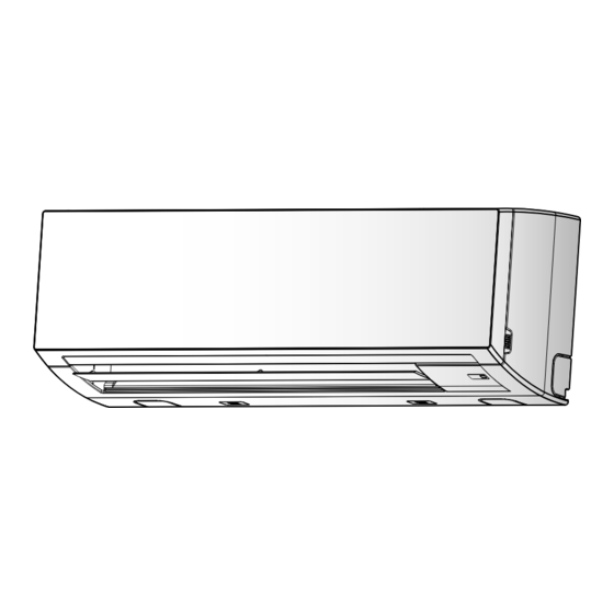
AIR CONDITIONER (SPLIT TYPE) Installation Manual Indoor Unit For commercial use Model name: High Wall Type RAV-SM307KRTP-E RAV-SM407KRTP-E Installation Manual English... -
Page 2: Table Of Contents
The qualifi ed installer is a person who installs, maintains, relocates and removes the air conditioners made by Toshiba Carrier Corporation. He or she has been trained to install, maintain, relocate and Accessory parts ............4... -
Page 3: Warning Indications On The Air Conditioner Unit
■ Warning indications on the air conditioner unit Defi nition of Protective Gear When the air conditioner is to be transported, installed, maintained, repaired or removed, wear protective gloves and ‘safety’ work clothing. In addition to such normal protective gear, wear the protective gear described below when undertaking the special Warning indication Description work detailed in the table below. -
Page 4: Precautions For Safety
– 3 – Precautions for safety Installation • Install the air conditioner securely in a location where the base can sustain the weight adequately. If the strength is not enough, the unit may fall down resulting in injury. The manufacturer shall not assume any liability for the damage caused by not observing the description of this •... -
Page 5: Accessory Parts
Accessory parts Explanations given to user • Upon completion of the installation work, tell the user where the circuit breaker is located. If the user does not know where the circuit breaker is, he or she will not be able to turn it off in the event that trouble has occurred in the air conditioner. -
Page 6: Selection Of Installation Place
– 5 – Selection of installation place ■ Installation diagram of Indoor and outdoor units Avoid installing in the following places Before installing the wireless remote Select a location for the indoor unit where the cool or warm air will circulate evenly. controller Avoid installation in the following kinds of locations. -
Page 7: Installation
Cutting a hole and mounting installation ■ Wireless remote controller • A place where there are no obstacles such as a curtain that may block the signal from the indoor unit. plate • Do not install the remote controller in a place exposed to direct sunlight or close to a heating source, such as a stove. -
Page 8: Piping And Drain Hose Installation
– 7 – Piping and drain hose installation How to remove the drains cap ▼ In case of left piping After scribing slits of the front panel with a knife or a Clip the drain cap by needle-nose pliers and pull out. marking-off pin, cut them with a pair of nippers or an ■... -
Page 9: Indoor Unit Fixing
Indoor unit fi xing Gas side Heat insulator provided Drainage Refrigerant piping Pass the pipe through the hole in the wall, Run the drain hose sloped downwards. and hook the indoor unit on the installation CAUTION plate at the upper hooks. Indoor unit shield pipe Liquid side NOTE... - Page 10 – 9 – • ■ Wireless remote controller Projection margin in fl aring: B (unit: mm) Use the tightening torque levels as listed in the table Open the valve fully below. Open the valve of the outdoor unit fully. A hexagonal A-B selection (Unit: N·m) Outer dia.
-
Page 11: Electrical Connection
Electrical connection ■ Wiring between indoor unit and outdoor unit Figure below shows the wiring connections between the indoor and outdoor units and between WARNING the indoor units and remote controller. The wires indicated by the broken lines or dot-and-dash lines are provided at the locally. -
Page 12: Wiring Connection
– 11 – ■ Wiring connection (twin, ▼ When using optional wired remote controller ■ Wiring connection The system interconnection wire and the wired remote Earth screw triple, double twin system) (single system) controller wire can be connected without removing the front panel. -
Page 13: Applicable Controls
Applicable ■ Basic procedure for changing Terminal block for wired Each time button is pushed, indoor remote controller / settings unit numbers in the control group change Central control controls cyclically. Select the indoor unit to change Earth screw Change the settings while the air conditioner is not settings for. -
Page 14: Power Saving Mode
– 13 – ■ Filter sign setting ■ Power saving mode ■ Remote controller switch Push button to return to the normal monitoring function display. According to the installation condition, the filter sign ◆ Performing settings of the power term (notification of filter cleaning) can be changed. Indoor unit data saving mode This function is available to call the service monitor... -
Page 15: Group Control
■ Group control Group control for system of multiple units One remote controller can control maximum 8 indoor units as a group. Simultaneous twin, triple or double twin system ▼ Group control in single system A combination with an outdoor unit allows simultaneous ON / OFF operation of the indoor units. The following system patterns are available. - Page 16 – 15 – [Procedure example] To recognize the position of the 3) Push button. If there is other indoor unit to be changed, In this time, the setup finishes when the corresponding indoor unit though the Manual address setup procedure repeat procedure to change the display changes from flashing to lighting.
- Page 17 ■ 8 °C operation (SDI series4 ■ Central control system ▼ Centrally control the system by the SDI, DI series on their own setting for the terminating resistor is required. and DI series4 only) Air conditioners at multiple locations can be controlled •...
- Page 18 – 17 – How to set the SW01 ▼ Centrally control the system by connecting to the TCC-LINK central control system. Remove the screws and detach the electrical control box. Remove the front panel. Setting central control addresses • When air conditioners of the SDI, DI series are connected to the TCC-LINK central control system for central Before removing the front panel, direct the horizontal louver to the direction shown in the control using this product, set the addresses of indoor units using the following procedure.
- Page 19 Indoor unit line address manual setting / change Indoor unit line address manual setting / change [For 29 or less refrigeration systems (when they are used together with the SMMS series, the number [For 30 or more refrigeration systems (when they are used together with the SMMS series, the number of refrigeration systems of the SMMS series is included.)] of refrigeration systems of the SMMS series is included.)] Since all line addresses are set to “1”...
-
Page 20: Test Run
– 19 – Test run ■ When a test run is not performed properly ■ Before test run Select the operation mode with When a test run is not performed properly, refer button, [ Cool] or [ Heat]. to the error code and the part to be checked on •... -
Page 21: Maintenance
Maintenance CAUTION • Do not start the air conditioner while leaving air fi lter removed. Daily maintenance ◆ • Push the fi lter reset button. ( indication will be turn off.) Mount the air fi lter Cleaning of air fi lter Turn on the circuit breaker, then push the ◆... -
Page 22: Troubleshooting
– 21 – Troubleshooting ■ Error codes and parts to be checked ■ Confirmation and check ■ Confirmation of error log Wired Wireless remote controller remote Sensor block display of controller When an error occurred in the air conditioner, an error When an error occurred on the air conditioner, receiving unit Judging... - Page 23 Wired Wired Wireless remote controller Wireless remote controller remote remote Sensor block display of Sensor block display of controller controller receiving unit receiving unit Judging Parts to be checked / Judging Parts to be checked / display display Main defective parts conditioner Main defective parts conditioner...
- Page 24 144 / 9 Moo 5, Bangkadi Industrial Park, Tivanon Road, Tambol Bangkadi, Amphur Muang, Pathumthani 12000, Thailand 1111056499...