Table of Contents
Advertisement
Quick Links
CHAPTER 1. Configuration
CHAPTER 2. Installation in MX-3500/4500 series
CHAPTER 3. Installation in MX-5500N/6200N/7000N
Parts marked with "
" are important for maintaining the safety of the set. Be sure to replace these parts with
specified ones for maintaining the safety and performance of the set.
INSTALLATION MANUAL
DIGITAL FULL COLOR
MULTIFUNCTIONAL SYSTEM OPTION
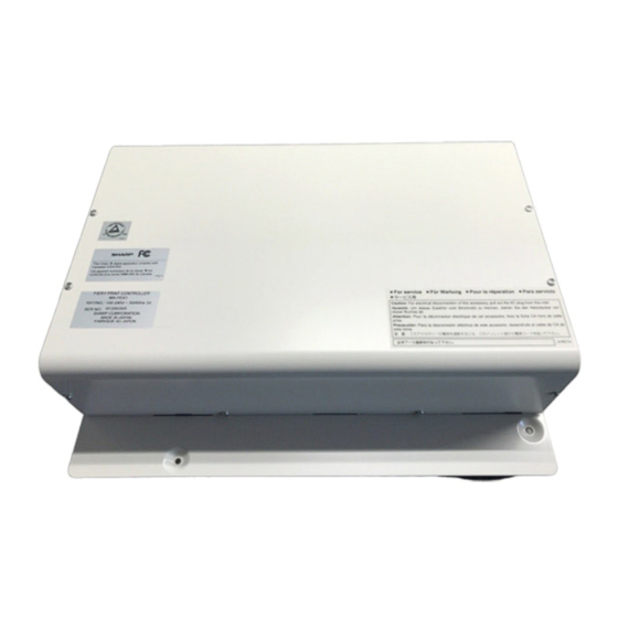
PRINT CONTROLLER UNIT
MODEL
CONTENTS
SHARP CORPORATION
CODE: 00ZMXPEX2/I1E
MX-PEX1
MX-PEX2
This document has been published to be used
for after sales service only.
The contents are subject to change without notice.
Advertisement
Table of Contents

Summary of Contents for Sharp MX-PEX1
- Page 1 INSTALLATION MANUAL CODE: 00ZMXPEX2/I1E DIGITAL FULL COLOR MULTIFUNCTIONAL SYSTEM OPTION PRINT CONTROLLER UNIT MX-PEX1 MX-PEX2 MODEL CONTENTS CHAPTER 1. Configuration CHAPTER 2. Installation in MX-3500/4500 series CHAPTER 3. Installation in MX-5500N/6200N/7000N Parts marked with " " are important for maintaining the safety of the set. Be sure to replace these parts with specified ones for maintaining the safety and performance of the set.
-
Page 2: Combination List
7000N) even after completion of the setup. NOTE: MX-PEX1 was shipped after setting the basic setting (the information of MFP) by default, but MX-PEX2 is shipped in the fac- tory shipment setting (without setting of the information of MFP), because it is necessary to detect MFP when turning on the power. -
Page 3: Turn Off The Power Of The Main Unit
2. Install of the I/F unit [2] Installation in MX-3500/4500 MX-PEX2 Service Manual series Remove the ozone filter cover. Remove the screws, and remove the right rear cabinet cover. <Note before installation> * Start installation after checking that the LINE indicator and the DATA indicator below it on the operation panel are neither lit nor blinking. -
Page 4: Installation Of The Printer Controller
Restore the MFP cnt PWB unit to the main unit, and fix with the Engage the printer controller unit with the step screws, and screws. slide it to the right door side. Fix the print controller unit using the two screws of the four Cut out the cut-out portion of the right rear cabinet cover for screws removed in step 1. -
Page 5: Caution Label Attachment
Insert the power plug of the main unit to the outlet. CAUTION: CAUTION: After the MX-PEX1/PEX2 is installed, be sure the setting of items as follows again. (Reconfiguration in setting is required, because the information that had been keeping before installa- tion is initialized.) -
Page 6: Removal Of The Control Box
[3] Installation in MX-5500N/ 2. Removal of the control box MX-PEX2 Service Manual 6200N/7000N Remove the screw of right rear cabinet, push down the right rear cabinet. Disengage the pawls, and remove the right rear <Note before installation> cabinet so that slide to the front side. * Start installation after checking that the LINE indicator and the DATA indicator below it on the operation panel are neither lit nor blinking. -
Page 7: Installation Of The Control Box
3. Install of the I/F unit Push the control box into the main unit. Lay the finger handle. Fix with the screws. Remove the three screws of the MFP cnt PWB. Install the I/F unit (package part No.1) with the three screws that was detached from MFP cnt PWB. -
Page 8: Turn On The Power Switch Of The Print Controller Unit And Main Unit
5. Installation of the printer controller Connect the cable (A) of the I/F unit, the LAN cable (package part No. 3), and the AC power cord (C) (package part No. 4). Remove the four screws from the rear cabinet. Attach two step screws (package part No. - Page 9 8. Note for network setting and Insert the power plug of the main unit into the power outlet. calibration resetting CAUTION: CAUTION: After the MX-PEX2 is installed, be sure the setting of items as follows again. (Reconfiguration in setting is required, because the information that had been keeping before installa- tion is initialized.) System setting →...
-
Page 10: Lead-Free Solder
LEAD-FREE SOLDER The PWB’s of this model employs lead-free solder. The “LF” marks indicated on the PWB’s and the Service Manual mean “Lead-Free” solder. The alphabet following the LF mark shows the kind of lead-free solder. Example: <Solder composition code of lead-free solder> Solder composition Solder composition code Solder composition... - Page 11 CAUTION FOR BATTERY REPLACEMENT (Danish) ADVARSEL ! Lithiumbatteri – Eksplosionsfare ved fejlagtig håndtering. Udskiftning må kun ske med batteri af samme fabrikat og type. Levér det brugte batteri tilbage til leverandoren. (English) Caution ! Danger of explosion if battery is incorrectly replaced. Replace only with the same or equivalent type recommended by the manufacturer.
- Page 12 COPYRIGHT © 2006 BY SHARP CORPORATION All rights reserved. Printed in Japan. No part of this publication may be reproduced, stored in a retrieval system, or transmitted, in any form or by any means, electronic; mechanical; photocopying; recording or otherwise without prior written permission of the publisher.


