Table of Contents
Advertisement
Please refer to the original service manual for:
CD Mechanism Unit (BRS1C), Order No. PSG1102001CE
Speaker system SB-AKX72PN-K, Order No. PSG1103048CE
TABLE OF CONTENTS
1 Safety Precautions----------------------------------------------- 3
1.1. General Guidelines---------------------------------------- 3
1.2. Before Use (For PH only)-------------------------------- 3
1.3. Caution For Fuse Replacement------------------------ 3
1.4. Before Repair and Adjustment ------------------------- 4
1.5. Protection Circuitry ---------------------------------------- 4
1.6. Safety Parts Information --------------------------------- 5
2 Warning -------------------------------------------------------------- 6
to Electrostatic Sensitive (ES) Devices -------------- 6
2.2. Precaution of Laser Diode------------------------------- 7
2.4. Handling Precautions for Traverse Unit-------------- 9
3 Service Navigation ----------------------------------------------11
3.1. Service Information -------------------------------------- 11
4 Specifications ----------------------------------------------------12
Model No.
Product Color: (K)...Black Type
PAGE
5 Location of Controls and Components------------------ 13
5.1. Main Unit Key Button Operation---------------------- 13
5.2. Remote Control Key Button Operation ------------- 14
5.3. Media Information---------------------------------------- 15
6 Self-Diagnostic and Special Mode Setting ------------- 16
6.1. Cold-Start -------------------------------------------------- 16
6.2. Doctor Mode Table--------------------------------------- 17
(BRS1C))--------------------------------------------------- 19
6.4. Self-Diagnostic Mode ----------------------------------- 20
6.5. Self-Diagnostic Error Code Table -------------------- 21
6.6. Sales Demonstration Lock Function ---------------- 22
7 Troubleshooting Guide --------------------------------------- 23
7.2. Part Location ---------------------------------------------- 24
7.3. D-Amp IC Operation & Control ----------------------- 27
© Panasonic Corporation 2011. All rights reserved.
Unauthorized copying and distribution is a violation
of law.
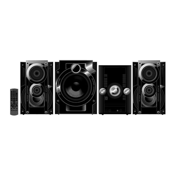
CD Stereo System
SA-AKX72PH
SA-AKX72PN
PSG1103014CE
PAGE
Advertisement
Table of Contents

Related Manuals for Panasonic SA-AKX72PH


Summary of Contents for Panasonic SA-AKX72PH
-
Page 1: Table Of Contents
7.1. Troubleshooting Guide for F61 and/ or F76 ------- 23 3.1. Service Information -------------------------------------- 11 7.2. Part Location ---------------------------------------------- 24 4 Specifications ----------------------------------------------------12 7.3. D-Amp IC Operation & Control ----------------------- 27 © Panasonic Corporation 2011. All rights reserved. Unauthorized copying and distribution is a violation of law. - Page 2 8 Service Fixture & Tools --------------------------------------- 29 14.1. Overall Simplified Block Diagram-------------------- 85 8.1. Service Tools and Equipment ------------------------- 29 14.2. D-Amp Block Diagram---------------------------------- 86 9 Disassembly and Assembly Instructions --------------- 30 15 Block Diagram --------------------------------------------------- 87 9.1. Disassembly Flow Chart-------------------------------- 31 15.1.
-
Page 3: Safety Precautions
1 Safety Precautions 1.1. General Guidelines 1. When servicing, observe the original lead dress. If a short circuit is found, replace all parts which have been overheated or damaged by the short circuit. 2. After servicing, see to it that all the protective devices such as insulation barriers, insulation papers shields are properly installed. -
Page 4: Before Repair And Adjustment
1.4. Before Repair and Adjustment Disconnect AC power to discharge unit AC Capacitors as such (C5700, C5701, C5703, C5704, C5705, C5708) through a 10 Ω, 10 W resistor to ground. Caution: DO NOT SHORT-CIRCUIT DIRECTLY (with a screwdriver blade, for instance), as this may destroy solid state devices. After repairs are completed, restore power gradually using a variac, to avoid overcurrent. -
Page 5: Safety Parts Information
1.6. Safety Parts Information Safety Parts List: There are special components used in this equipment which are important for safety. These parts are marked by in the Schematic Diagrams, Exploded View & Replacement Parts List. It is essential that these critical parts should be replaced with manufacturer’s specified parts to prevent shock, fire or other hazards. -
Page 6: Warning
2 Warning 2.1. Prevention of Electrostatic Discharge (ESD) to Electrostatic Sensitive (ES) Devices Some semiconductor (solid state) devices can be damaged easily by static electricity. Such components commonly are called Elec- trostatically Sensitive (ES) Devices. Examples of typical ES devices are integrated circuits and some field-effect transistors and semiconductor "chip"... -
Page 7: Precaution Of Laser Diode
2.2. Precaution of Laser Diode Caution: This product utilizes a laser diode with the unit turned “on”, invisible laser radiation is emitted from the pickup lens. Wavelength: 790 nm (CD) Maximum output radiation power from pickup: 100 µW/VDE Laser radiation from the pickup unit is safety level, but be sure the followings: 1. -
Page 8: Service Caution Based On Legal Restrictions
2.3. Service caution based on Legal restrictions 2.3.1. General description about Lead Free Solder (PbF) The lead free solder has been used in the mounting process of all electrical components on the printed circuit boards used for this equipment in considering the globally environmental conservation. The normal solder is the alloy of tin (Sn) and lead (Pb). -
Page 9: Handling Precautions For Traverse Unit
2.4. Handling Precautions for Traverse Unit The laser diode in the optical pickup unit may break down due to static electricity of clothes or human body. Special care must be taken avoid caution to electrostatic breakdown when servicing and handling the laser diode in the traverse unit. Cautions to Be Taken in Handling the Optical Pickup Unit 2.4.1. -
Page 10: Grounding For Electrostatic Breakdown Prevention
Grounding for electrostatic breakdown prevention 2.4.2. Some devices such as the DVD player use the optical pickup (laser diode) and the optical pickup will be damaged by static electric- ity in the working environment. Proceed servicing works under the working environment where grounding works is completed. 2.4.2.1. -
Page 11: Service Navigation
3 Service Navigation 3.1. Service Information This service manual contains technical information which will allow service personnel’s to understand and service this model. Please place orders using the parts list and not the drawing reference numbers. If the circuit is changed or modified, this information will be followed by supplement service manual to be filed with original service manual. -
Page 12: Specifications
87.5 to 108.0 MHz (100 kHz step) analyzer. 75 Ω (unbalanced) Antenna terminal (s) System: SC-AKX72PH-K Amplitude Modulation (AM) Main Unit: SA-AKX72PH-K Frequency range Front Speakers: SB-AKX72PN-K For PH only 522 to 1629 kHz (9 kHz step) System: SC-AKX72PN-K 520 to 1630 kHz (10 kHz step) -
Page 13: Location Of Controls And Components
5 Location of Controls and Components 5.1. Main Unit Key Button Operation... -
Page 14: Remote Control Key Button Operation
5.2. Remote Control Key Button Operation... -
Page 15: Media Information
5.3. Media Information Note on CDs This system can access up to 99 tracks. This system can play MP3 files and CD-DA format audio CD-R/RW that have been finalized. This system can fail to play some CD-R/RW because of the condition of the recording. -
Page 16: Self-Diagnostic And Special Mode Setting
6 Self-Diagnostic and Special Mode Setting 6.1. Cold-Start Here is the procedure to carry out cold-start or initialize to shipping mode. 1. Unplug AC power cord 2. Press & hold [POWER] button 3. Plug AC power cord while [POWER] button being pressed FL Display will show “_ _ _ _ _ _ _ _”... -
Page 17: Doctor Mode Table
6.2. Doctor Mode Table 6.2.1. Doctor Mode Table 1 Item Key Operation FL Display Mode Name Description Front Key Doctor Mode To enter into Doctor Mode 1.In CD Mode: Press [ ] button on main unit follow by [4] and [7] on remote control. - Page 18 6.2.2. Doctor Mode Table 2 Item Key Operation FL Display Mode Name Description Front Key Cold Start To active cold start upon next AC In Doctor Mode: power up when reset start is execute 1. Press [DISPLAY/-DIMMER] the next time. button on remote control.
-
Page 19: Reliability Test Mode (Cd Mechanism Unit (Brs1C))
6.3. Reliability Test Mode (CD Mechanism Unit (BRS1C)) Below is the process flow chart of the aging test for the CD Mechanism Unit (BRS1C). OPEN First Track Operation Access OPEN wait First Track fot 1 s Play 5 s CLOSE Last Track Operation Access... -
Page 20: Self-Diagnostic Mode
6.4. Self-Diagnostic Mode In CD Mode: Service Mode To enter into Service Mode 1.Press and hold [ ] button on main unit for 2 secs. 2.Do not release [ ] button, press and hold [ ] on the remote control for 2 secs. 3.To exit, press [POWER, button on main unit. -
Page 21: Self-Diagnostic Error Code Table
6.5. Self-Diagnostic Error Code Table Self-Diagnostic Function (Refer Section 6.4. Self-Diagnostic Mode) provides information on any problems occurring for the unit and its respective components by displaying the error codes. These error code such as U**, H** and F** are stored in memory and held unless it is cleared. -
Page 22: Sales Demonstration Lock Function
6.6. Sales Demonstration Lock Function 6.6.1. Entering into sales Demo Mode Here is the procedures to enter into Sales Demonstration Lock. Step 1: Turn on the unit. Step 2: Select to any mode function, press and hold [ ] key and follow by [ / ] key pressed within 0.5 sec. OPEN/CLOSE Step 3: Hold both [ ] and [ / ] keys for 5 sec. -
Page 23: Troubleshooting Guide
7 Troubleshooting Guide 7.1. Troubleshooting Guide for F61 and/ or F76 This section illustrates the checking procedures when upon detecting the error of “F61” and “F76” after power up of the unit.It is for purpose of troubleshooting and checking in SMPS,D-Amp & Main P.C.B.. Symptom Checking Items Possible Fault(s) -
Page 24: Part Location
7.2. Part Location 7.2.1. SMPS P.C.B. AC Inlet: P5701 Fuse: Switching Regulator IC: IC5799 Switching Regulator Photocoupler: IC: IC5701 Thermistor: PC5702, PC5799 TH5860 Rectifier Diode: D5801, D5802 Transformer: Connector: T5701 CN5802 Photocoupler: PC5720 Fig. 1 SMPS P.C.B. - Page 25 7.2.2. Main P.C.B. Voltage Regulator IC: IC2010 DC/DC Converter IC: Connector: IC2011 ZJ2007 Fig. 2 Main P.C.B.
- Page 26 7.2.3. D-Amp P.C.B. Audio Digital Amp IC: IC5000 Audio Digital Audio Digital Amp IC: IC5400 Amp IC: IC5200 Fig. 3 D-Amp P.C.B.
-
Page 27: D-Amp Ic Operation & Control
7.3. D-Amp IC Operation & Control D-AMP IC Operation & Control 1) D-AMP IC (C1AB00000497) was used for this model. 2) Three control pins (signal send from micro-processor IC) were used to control the D-AMP IC operation such as muting, standby and normal operation. They are described as below: - Pin no Signal name Function... - Page 28 1170 ~ 1250 1260 ~ 1450 1460 ~ 1540 1550 ~ 1710 Table 4: F_HOP Control during 10 kHz Step Note: During activating, the 3 control pins namely MUTE_F, MUTE_A and MODE_DA must be used to cover the “Pop” sound cause by F-HOP switching.
-
Page 29: Service Fixture & Tools
8 Service Fixture & Tools 8.1. Service Tools and Equipment Prepare service tools before process service position. Service Tools Remarks Main P.C.B. (ZJ2007) - SMPS P.C.B. (CN5802) REXX1206 (15P Cable Wire) -
Page 30: Disassembly And Assembly Instructions
9 Disassembly and Assembly Instructions • Illustration is based on SA-AKX72PH-K Caution Note: • This section describes the disassembly and/or assembly procedures for all major printed circuit boards & main compo- nents for the unit. (You may refer to the section of “Main components and P.C.B Locations” as described in the service manual) •... -
Page 31: Disassembly Flow Chart
9.1. Disassembly Flow Chart 9.3. Top Cabinet 9.4. Tuner P.C.B. 9.18. SMPS P.C.B. 9.12. Main P.C.B. 9.5. Front Panel 9.19. Switching Regulator Unit IC (IC5701) 9.13. Voltage Regulator IC (IC2010) 9.20. Rectifier Diode 9.6. Jupiter P.C.B. (D5702) 9.14. D-Amp .P.C.B. 9.21. -
Page 32: Main Components And P.c.b. Locations
9.2. Main Components and P.C.B. Locations... -
Page 33: Disassembly Of Top Cabinet
9.3. Disassembly of Top Cabinet Step 4 Slightly lift up both side of Top Cabinet in an outward direction as shown. Step 1 Remove 2 screws on each side. Step 5 Remove Top Cabinet. Step 2 Remove 5 screws. Step 3 Slightly pull both side of Top Cabinet outwards as arrow shown. -
Page 34: Disassembly Of Tuner P.c.b
9.4. Disassembly of Tuner P.C.B. 9.5. Disassembly of Front Panel Unit • Refer to “Disassembly of Top Cabinet”. • Refer to “Disassembly of Top Cabinet”. Step 1 Remove 1 screw. Step 1 Detach 30P FFC at the connector (CN2000) on Jupiter P.C.B. - Page 35 Step 3 Push inwards slightly at the Bottom Chassis and release Step 5 Push inwards slightly at the Bottom Chassis and release tab at left side of Front Panel Unit.. tab at right side of Front Panel Unit. Step 4 Release tab at bottom. Step 6 Remove Front Panel Unit.
-
Page 36: Disassembly Of Jupiter P.c.b
9.6. Disassembly of Jupiter P.C.B. Step 3 Detach 7P connector (CN503) on Jupiter P.C.B. from 7P connector (CN6003) on USB P.C.B.. • Refer to “Disassembly of Top Cabinet”. Step 4 Remove Jupiter Unit. • Refer to “Disassembly of Front Panel Unit”. Step 1 Detach 30P FFC at the connector (CN601) on Jupiter P.C.B. -
Page 37: Disassembly Of Panel P.c.b
9.7. Disassembly of Panel P.C.B. Step 4 Remove D-Amp P.C.B. Holder. Step 5 Release catches by following the sequences (1-6). • Refer to “Disassembly of Top Cabinet”. • Refer to “Disassembly of Front Panel Unit”. • Refer to “Disassembly of Jupiter P.C.B.”. Step 1 Remove the Volume Knob. -
Page 38: Disassembly Of Remote Sensor P.c.b
Step 7 Desolder 12pins at (ZJ6002A) on Panel P.C.B. 9.8. Disassembly of Remote Sensor Step 8 Remove the Panel P.C.B. P.C.B. • Refer to “Disassembly of Top Cabinet Unit”. • Refer to “Disassembly of Front Panel Unit”. • Refer to “Disassembly to Jupiter P.C.B.”. •... -
Page 39: Disassembly Of Usb P.c.b
9.9. Disassembly of USB P.C.B. 9.10. Disassembly of Music Port • Refer to “Disassembly of Top Cabinet”. P.C.B. • Refer to “Disassembly of Front Panel Unit”. • Refer to “Disassembly of Top Cabinet”. • Refer to “Disassembly of Jupiter P.C.B”. •... - Page 40 Step 4 Release 2 catches. Caution: During assembling, ensure the 2P Cable Wire is dressed into the outer slot properly. Step 5 Lift up Music Port P.C.B. Caution: During assembling, ensure that Music Port P.C.B. is properly located & fully catched onto Front Panel. Step 6 Desolder 12 pins (ZJ6002) on Music Port P.C.B.
-
Page 41: Disassembly Of Cd Lid
9.11. Disassembly of CD Lid 9.12. Disassembly of Main P.C.B. • Refer to “Disassembly of Top Cabinet”. • Refer to “Disassembly of Top Cabinet”. • Refer to “Disassembly of Front Panel Unit”. • Refer to “Disassembly of Front Panel Unit”. Step 1 Remove the spring as arrow shown in order of Step 1 Detach 2P Wire at the connector (CN2006) on Main sequence (1) to (3). - Page 42 Step 6 Remove 1 screw. Caution: During assembling, ensure that earth plate is bended flat against the Main P.C.B. properly when inserted Step 7 Detach Main P.C.B. from Rear Panel according to arrow to locators. shown. Step 8 Detach 27P FFC at the connector (CN2009) on Main P.C.B..
-
Page 43: Replacement Of Voltage Regulator Ic (Ic2010)
9.13. Replacement of Voltage Regu- 9.13.2. Assembly of Voltage Regulator IC (IC2010) lator IC (IC2010) Step 1 Apply grease to the Heatsink. • Refer to “Disassembly of Main P.C.B.”. Step 2 Fix the Voltage Regulator IC (IC2010) on Main P.C.B.. Caution: Ensure pins of the Voltage Regulator IC (IC2010) are properly seated on Main P.C.B.. -
Page 44: Disassembly Of D-Amp P.c.b
9.14. Disassembly of D-Amp P.C.B. Step 4 Remove 2 screws. • Refer to “Disassembly of Top Cabinet”. • Refer to “Disassembly of Front Panel Unit”. Step 1 Remove 2 screws. Step 2 Twist the Wire Holder to release 6P Cable Wire. Step 3 Detach 6P Cable Wire at the connector (CN5801) on SMPS P.C.B. - Page 45 Caution: During assembling, ensure that D-Amp Brackets Step 7 Remove 2 screws. is seated on the locator of Inner Chassis properly. Step 8 Remove D-Amp P.C.B.. Caution: Keep the D-Amp Brackets in safe place, place it back during assembling. Step 6 Detach 17P FFC at the connector (CN5050) on D-Amp P.C.B..
-
Page 46: Replacement Of Audio Digital Amp Ic (Ic5000)
9.15. Replacement of Audio Digital 9.15.1. Assembly of Audio Digital Amp IC (IC5000) Amp IC (IC5000) Step 1 Fix the Audio Digital Amp IC (IC5000) on to D-Amp • Refer to “Disassembly of D-Amp P.C.B.”. P.C.B.. Step 2 Screw back TR Spring to hold the Audio Digital Amp IC Step 1 Flip over D-Amp P.C.B.. -
Page 47: Replacement Of Audio Digital Amp Ic (Ic5400)
9.16. Replacement of Audio Digital 9.16.1. Assembly of Audio Digital Amp IC (IC5400) Amp IC (IC5400) Step 1 Fix the Audio Digital Amp IC (IC5400) on to D-Amp • Refer to “Disassembly of D-Amp P.C.B.”. P.C.B.. Step 2 Screw back TR Spring to hold the Audio Digital Amp IC Step 1 Flip over D-Amp P.C.B.. -
Page 48: Replacement Of Audio Digital Amp Ic (Ic5200)
9.17. Replacement of Audio Digital 9.17.1. Assembly of Audio Digital Amp IC (IC5200) Amp IC (IC5200) Step 1 Fix the Audio Digital Amp IC (IC5200) on to D-Amp • Refer to “Disassembly of D-Amp P.C.B.”. P.C.B.. Step 2 Screw back TR Spring to hold the Audio Digital Amp IC Step 1 Flip over D-Amp P.C.B.. -
Page 49: Disassembly Of Smps P.c.b
9.18. Disassembly of SMPS P.C.B. Step 4 Remove the Inner Fan Unit. Step 5 Detach 15P Cable Wire at the connector (CN5802) on • Refer to “Disassembly of Top Cabinet.”. SMPS P.C.B.. • Refer to “Disassembly of Front Panel Unit”. •... -
Page 50: Replacement Of Switching Regulator Ic (Ic5701)
9.19. Replacement of Switching Reg- Step 2 Remove 1 screw. Step 3 Remove the Switching Regulator IC (IC5701). ulator IC (IC5701) Caution: Avoid touching the Heatsink A due to its high temperature after prolonged use. Touching it may lead to •... - Page 51 9.19.2. Assembly of Switching Regulator Step 4 Solder pins of the Switching Regulator IC (IC5701) on the solder side of SMPS P.C.B.. IC (IC5701) Step 1 Apply grease to the Heatsink A. Step 2 Fix the Switching Regulator IC (IC5701) to the SMPS P.C.B..
-
Page 52: Replacement Of Rectifier Diode (D5702)
9.20. Replacement of Rectifier Diode Step 3 Remove 1 screw at Switching Regulator IC (IC5701). Step 4 Remove the Heatsink A with Rectifier Diode (D5702). (D5702) Step 5 Remove 1 screw. • Refer to “Disassembly of SMPS P.C.B.”. Step 6 Remove the Rectifier Diode (D5702) from the Heatsink Caution: Avoid touching the Heatsink A due to its high 9.20.1. - Page 53 9.20.2. Assembly of Rectifier Diode Step 5 Solder pins of the Rectifier Diode (D5702) on the solder side of SMPS P.C.B.. (D5702) Step 6 Solder pins of the Heatsink A on the solder side of Step 1 Apply grease to the Heatsink A. SMPS P.C.B..
-
Page 54: Replacement Of Rectifier Diode (D5801)
9.21. Replacement of Rectifier Diode 9.21.2. Assembly of Rectifier Diode (D5801) (D5801) Step 1 Apply grease to the Heatsink B. • Refer to “Disassembly of SMPS P.C.B.”. Step 2 Fix the Rectifier Diode (D5801) on SMPS P.C.B. Caution: Ensure pins of the Rectifier Diode (D5801) is properly inserted on SMPS P.C.B. -
Page 55: Replacement Of Rectifier Diode (D5802)
9.22. Replacement of Rectifier Diode 9.22.2. Assembly of Rectifier Diode (D5802) (D5802) Step 1 Apply grease to the Heatsink B. • Refer to “Disassembly of SMPS P.C.B.”. Step 2 Fix the Rectifier Diode (D5802) on SMPS P.C.B.. Caution: Ensure pins of the Rectifier Diode (D5802) is properly inserted on SMPS P.C.B. -
Page 56: Replacement Of Rectifier Diode (D5803)
9.23. Replacement of Rectifier Diode 9.23.2. Assembly of Rectifier Diode (D5803) (D5803) Step 1 Apply grease to the Heatsink B. • Refer to “Disassembly of SMPS P.C.B.”. Step 2 Fix Rectifier Diode (D5803) on SMPS P.C.B. Caution: Ensure pins of the Rectifier Diode (D5803) are properly inserted on SMPS P.C.B. -
Page 57: Disassembly Of Cd Mechanism Unit (Brs1C)
9.24. Disassembly of CD Mecha- Step 4 Remove 2 screws. nism Unit (BRS1C) • Refer to “Disassembly of Top Cabinet”. • Refer to “Disassembly of Front Panel Unit”. • Refer to “Disassembly of D-Amp P.C.B.”. Step 1 Detach 15P Wire at the connector (CN5802) on SMPS P.C.B.. - Page 58 Step 6 Detach Voltage Selector P.C.B. from Rear Panel as Step 7 Lift up SMPS Inner Chassis Unit. arrow shown. Caution: During assembling, ensure that SMPS Inner Chassis is catched onto Rear Panel properly.
-
Page 59: Disassembly Of Rear Panel
Step 8 Remove 2 screws. 9.25. Disassembly of Rear Panel • Refer to “Disassembly of Top Cabinet”. • Refer to “Disassembly of Tuner P.C.B.”. Step 1 Remove 8 screws. Step 2 Detach 2P Wire at the connector (CN2006) on Main Step 9 Lift up &... -
Page 60: Disassembly Of Voltage Selector P.c.b
Step 4 Lift up SMPS Inner Chassis Unit to release the catch 9.26. Disassembly of Voltage Selec- between the SMPS Inner Chassis Unit & the Rear Panel. tor P.C.B. • Refer to “Disassembly of Top Cabinet”. Step 1 Remove 1 screw. Step 5 Release 2 tabs. - Page 61 Step 3 Desolder 2 Wire pins, TL5 (Black), TL6 (Red) on the Voltage Selector P.C.B.. Step 4 Remove Voltage Selector P.C.B..
-
Page 62: Replacement Of Traverse Unit
10 Replacement of Traverse Step 2: Slide the tray out fully. Unit 10.1. Disassembly of Traverse Unit • Refer to “Disassembly of CD Mechanism Unit (BRS1C)”. Caution: Refer to “2.4 Handling Precaution for Traverse Unit” to prevent static damage to the Optical Pickup Unit. Note: 1. - Page 63 Step 4: Release the guide as shown & slide the Traverse Slide Step 6: Lift the Traverse Unit by approximately 45°. Plate to the end. Step 7: Slide out the traverse unit as arrow shown. Step 5: Detach 5P FFC at the connector (CN7003) on CD Servo P.C.B..
-
Page 64: Assembly Of Traverse Unit
10.2. Assembly of Traverse Unit Step 2: Slot the Traverse Unit at approximately 45° into the mecha chassis as arrow shown. Step 1: Release the guide as shown & slide the Traverse Slide Plate to the end. - Page 65 Step 3: Ensure the Traverse Unit seated properly onto the Step 6: Slide the Traverse Slide Plate unit it stop at the Guide.. Groove.. Step 7: Slot the Tray into the guides as Picture shown. Step 4: Slide Traverse Slide Plate to lock the Traverse Unit as shown.
-
Page 66: Disassembly Of Cd Servo P.c.b
Step 8: Ensure the guides is align with the groove when sliding 10.3. Disassembly Servo the tray in. P.C.B. • Refer to “Disassembly of CD Mechanism Unit (BRS1C)”. • Refer to “Replacement of Traverse Unit”. Caution: It is required to short the circuit. Step 1: Solder the 3 solder points. - Page 67 Caution 2: During assembling, desolder the solder points. Step 5 Slightly lift up the CD Servo P.C.B. Step 6 Flip the CD Servo P.C.B. Step 2 Remove 3 screws. Step 3 Desolder 4 pins. Step 4 Detach 5P FFC at the connector (CN7003) on CD Servo P.C.B..
- Page 68 Step 9 Ground the 24P FFC with a short pin.
-
Page 69: Service Position
11 Service Position 11.2. Checking and Repairing of D- Amp P.C.B. Note: For description of the disassembly procedures, see the Section 9. Step 1 Remove Top Cabinet. Step 2 D-Amp P.C.B. can be checked & repaired at its original 11.1. Checking and Repairing of position. -
Page 70: Checking And Repairing Of Jupiter P.c.b
11.4. Checking and Repairing of 11.4.2. Checking and Repairing side A of Jupiter P.C.B. Jupiter P.C.B. Step 1 Remove Top Cabinet. 11.4.1. Checking and Repairing side B of Step 2 Remove Front Panel Unit. Step 3 Remove the Jupiter P.C.B. Jupiter P.C.B. -
Page 71: Checking And Repairing Of Smps P.c.b
11.5. Checking and Repairing of Step 11 Extend the Cable Wire with extension Cable Wire (REXX1206) (15P Cable Wire from ZJ2007 to CN5802). SMPS P.C.B. Step 12 Connect 6P Cable Wire to the connector (CN5801) on Step 1 Remove Top Cabinet. SMPS P.C.B.. -
Page 72: Checking And Repairing Of Cd Servo P.c.b
11.6. Checking and Repairing of CD Step 13 Latch D-Amp P.C.B. onto Inner Chassis. Step 14 Attach 6P Cable Wire to the connector (CN5801) on Servo P.C.B. SMPS P.C.B.. Step 1 Remove Top Cabinet. Step 15 Attach 27P FFC to the connector (CN7002) on CD Step 2 Remove Front Panel Unit. -
Page 73: Voltage & Waveform Chart
Measuring instrument and its measuring condition and product itself. 12.1. CD Servo P.C.B. REF NO. IC7002 MODE CD PLAY IC7002 REF NO. MODE CD PLAY Q7601 REF NO. MODE CD PLAY SA-AKX72PH/PN CD SERVO P.C.B. -
Page 74: Main P.c.b. (1/3)
STANDBY REF NO. IC2004 MODE POWER ON 11.0 STANDBY 11.0 IC2006 REF NO. MODE POWER ON STANDBY IC2009 REF NO. MODE POWER ON 10.6 STANDBY 10.6 IC2010 REF NO. MODE POWER ON 16.0 12.2 STANDBY 16.0 12.2 SA-AKX72PH/PN MAIN P.C.B. -
Page 75: Main P.c.b. (2/2)
Q2031 Q2033 QR2005 QR2006 REF NO. MODE POWER ON 16.4 16.5 11.6 TUNER 16.4 16.5 11.6 REF NO. IC2000 MODE CD PLAY STANDBY IC2000 REF NO. MODE CD PLAY STANDBY REF NO. IC2000 MODE CD PLAY STANDBY SA-AKX72PH/PN MAIN P.C.B. -
Page 76: Main P.c.b. (3/3)
CD PLAY STANDBY QR2002 QR2003 QR2004 REF NO. MODE CD PLAY STANDBY SA-AKX72PH/PN MAIN P.C.B. 12.5. Panel P.C.B. IC6001 REF NO. MODE POWER ON -14.4 -14.3 -18.2 -22.1 -20.2 -22.1 -18.2 STANDBY -12.5 -16.3 -14.3 -22.1 -20.2 -22.1 -12.4 IC6001 REF NO. -
Page 77: Music Port P.c.b
12.6. Music Port P.C.B. IC6000 REF NO. MODE CD PLAY STANDBY SA-AKX72PH/PN MUSIC PORT P.C.B. 12.7. Tuner P.C.B. IC52 REF NO. MODE TUNER SA-AKX72PH/PN TUNER P.C.B. -
Page 78: Jupiter P.c.b. (1/3)
CD PLAY STANDBY IC701 REF NO. MODE CD PLAY STANDBY REF NO. IC751 MODE CD PLAY STANDBY IC751 REF NO. MODE CD PLAY STANDBY IC751 REF NO. MODE CD PLAY STANDBY REF NO. IC801 MODE CD PLAY STANDBY SA-AKX72PH/PN JUPITER P.C.B. -
Page 79: Jupiter P.c.b. (2/3)
CD PLAY STANDBY REF NO. IC801 MODE CD PLAY STANDBY IC801 REF NO. MODE CD PLAY STANDBY REF NO. IC801 MODE CD PLAY STANDBY IC801 REF NO. MODE CD PLAY STANDBY REF NO. IC801 MODE CD PLAY STANDBY SA-AKX72PH/PN JUPITER P.C.B. -
Page 80: Jupiter P.c.b. (3/3)
12.10. Jupiter P.C.B. (3/3) IC802 REF NO. MODE CD PLAY STANDBY Q801 REF NO. MODE CD PLAY STANDBY SA-AKX72PH/PN JUPITER P.C.B. 12.11. D-Amp P.C.B. IC5000 REF NO. MODE CD PLAY -34.8 -26.3 35.1 -0.1 -35.0 -24.9 -35.0 -0.1 35.1 -34.8 -34.8 34.8 34.8 STANDBY -34.8 -26.3 35.1... -
Page 81: Smps P.c.b
POWER ON 19.7 19.7 19.0 19.6 35.2 STANDBY 19.7 19.7 19.0 19.6 35.2 Q5862 Q5898 Q5899 QR5801 QR5802 REF NO. MODE POWER ON -3.0 STANDBY -2.9 QR5810 QR5811 QR5812 REF NO. MODE POWER ON -34.5 STANDBY -34.6 SA-AKX72PH/PN SMPS P.C.B. -
Page 82: Waveform Table
12.13. Waveform Table 0.1Vp-p(200usec/div) 4Vp-p(200usec/div) 0.2Vp-p(200usec/div) 1.3Vp-p(200usec/div) 2Vp-p(200usec/div) 2.4Vp-p(200usec/div) 3.6Vp-p(50nsec/div) 2.2Vp-p(50nsec/div) 1.4Vp-p(5usec/div) 2.8Vp-p(5usec/div) 5.6Vp-p(1usec/div) 0.84Vp-p(200usec/div) 80Vp-p(1usec/div) 0.84Vp-p(200usec/div) 5.6Vp-p(1usec/div) 0.84Vp-p(200usec/div) 80Vp-p(1usec/div) 0.84Vp-p(200usec/div) 5.6Vp-p(1usec/div) 0.84Vp-p(200usec/div) - Page 83 80Vp-p(1usec/div) 0.84Vp-p(200usec/div) 1.5Vp-p(1usec/div)
-
Page 84: Illustration Of Ics, Transistor And Diode
13 Illustration of ICs, Transistor and Diode C0HBB0000057 (44P) C0ABBB000230 (8P) C1BA00000497 (23P) RFKWMAKX72M0 C3ABQY000058 (64P) RFKWFAKX72J0 C1AB00003256 (52P) C3EBFY000006 (8P) C0ABBA000159 (8P) (100P) (48P) MN6627553PA (80P) C0FBAK000026 (16P) C1AB00003130 (14P) MN2WS0042NA (216P) C0FBBY000027 (16P) No.1 No.1 No.1 C0JBAB000902 C0GBY0000117 C1AB00003202 (20P) C3FBXY000026 C0AABB000125 (8P) -
Page 85: Simplified Block Diagram
14 Simplified Block Diagram 14.1. Overall Simplified Block Diagram... -
Page 86: D-Amp Block Diagram
14.2. D-Amp Block Diagram Subwoofer AMP (15mA) FROM Headphone SMPS Amp (15mA) +/-VCC = 35V, DIGITAL AMP IC (NXP) Bi-AMP filter (15mA) IC2010 +18V 245mA Regulator (11.5V ~ 19V) (403mA) +12V 1A Max BACKUP Reg4 +3.3V 200mA 9.9V 7.5V CD module motor +7.5V (200mA) discrete... -
Page 87: Block Diagram
USB REC LED USB REC LED 79 LED DRIVE NRST D2008 Q2011 3.3V RESET IC2003 RFKWMAKX72M0 TO SERVO & SYSTEM CONTROL MICRO PROCESSOR BLOCK (2/2) NOTE: “ * ” REF IS FOR INDICATION ONLY SA-AKX72PH/PN SERVO & SYSTEM CONTROL (1/2) BLOCK DIAGRAM... - Page 88 SMPS BP FROM/TO POWER SUPPLY SYNC SYNC SYNC DC DET PWR DC DET PWR DC DET2 TO SERVO & SYSTEM CONTROL BLOCK (1/2) D6019,D6022,D6027 LED SUPPLY CN2003 CN6001 LED SUPPLY LED SUPPLY SA-AKX72PH/PN SERVO & SYSTEM CONTROL (2/2) BLOCK DIAGRAM...
-
Page 89: Ic Terminal Chart
SIGNAL NAME SDRD9 PORT NAME PIN NO PIN NO PORT NAME DQ10 DQ10 SDRD10 HID0 DQ11 DQ11 SDRD11 HID1 DQ12 DQ12 SDRD12 HID2 DQ13 DQ13 SDRD13 HID3 DQ14 DQ14 SDRD14 HID4 DQ15 DQ15 SDRD15 HID5 HID6 HID7 SA-AKX72PH/PN IC TERMINAL CHART... -
Page 90: Audio
LVL MTR LVL MTR CIRCUIT AMPLIFIER CIRCUIT CIRCUIT IC2001 IC2002 VR6000 C0ABBB000230 MIC VOLUME OP-AMP MIC SW ZJ6002* ZJ6002A* MIC SW SERVO & MIC SW SYSTEM CONTROL NOTE: “ * ” REF IS FOR INDICATION ONLY SA-AKX72PH/PN AUDIO (1/2) BLOCK DIAGRAM... - Page 91 OUT1 10 JK5001 HIGH IC5200 C1BA00000497 POWER AMPLIFIER SUBWOOFER SUBWOOFER CN2004 CN5050 SUBWOOFER 21 IN2- BOOT2 15 2 IN1+ JK5001 OUT2 14 SUBWOOFER JK5001 OUT1 10 1 OSC BOOT1 9 23 MODE TO AUDIO BLOCK (1/2) SA-AKX72PH/PN AUDIO (2/2) BLOCK DIAGRAM...
-
Page 92: Power Supply
CIRCUIT C0DABFC00002 SHUNT FROM SERVO & REGULATOR SYSTEM CONTROL Q5899 CN5802 ZJ2007* ECO CTL ECO CTL ECO CTL ECO CTL QR5811 QR5812 SWITCH SWITCH COLD NOTE: “ * ” REF IS FOR INDICATION ONLY SA-AKX72PH/PN POWER SUPPLY (1/2) BLOCK DIAGRAM... - Page 93 VP DET VP DET MUSIC PORT P.C.B. ZJ6002A* ZJ6002* CN2003 CN6001 REMOTE SENSOR P.C.B. VREF+ CN6005 CN6006 VREF+ VREF SYS3.3V SYS3.3V CN2003 CN6001 SYS3.3V , VREF+ SYS3.3V 3.3V DVREF+ DVREF+ CN2003 CN6001 DVREF+ DVREF+ DVREF SA-AKX72PH/PN POWER SUPPLY (2/2) BLOCK DIAGRAM...
-
Page 94: Wiring Connection Diagram
(SIDE B) D-AMP P.C.B. (SOLDER SIDE) ZJ2007* CN2005 CN51 ZJ5500* JK5001 JK51 JK52 CN2003 CN2000 SUBWOOFER TO FAN UNIT SPEAKERS FM ANT AM ANT FOR DEBUG CN5050 FRONT NOTE: " * " REF IS FOR INDICATION ONLY. SA-AKX72PH/PN WIRING CONNECTION DIAGRAM... -
Page 95: Schematic Diagram
17 Schematic Diagram • For PH only 17.1. Schematic Diagram Notes • This schematic diagram may be modified at any time with the development of new technology. Notes: S5701: Voltage ADJ switch (For PH only). S6001: Radio/EXT-IN switch. S6002: Stop ( ) switch. -
Page 97: Cd Servo Circuit
3.3V CLOSE_SW LB7263 C7217 LB7266 SRDATA1 C7230 LB7265 SRDATA2 R7212 C7231 6.3V47 C7626 C7213 C7241 C7218 R7221 R7218 0.33 1000P 0.082 C7243 0.01 PGND C7232 LD-GND D7650 C7226 C7228 6.3V47 B0BC5R6A0266 1000P C7225 1000P C7227 LDSW SA-AKX72PH/PN CD SERVO CIRCUIT... - Page 98 0.01 6.3V47 TO OPTICAL PICKUP UNIT GND(PD) VREF(2.1V) (CD MECHANISM UNIT BRS1C) VCC(5V) C7731 C7732 C7734 C7733 C7711 R7713 CD-LD CD-LD MD/LPD MD/LPD R7712 K7102 LD-GND VREF NOTE: “ * ” REF IS FOR INDICATION ONLY SA-AKX72PH/PN CD SERVO CIRCUIT...
-
Page 99: Main Circuit
R2061 C2068 6.8K R2063 C2083 Q2041 0.022 R2054 R2355 C2087 B1ABCF000176 SWITCH R2356 R2377 C2039 SYS3.3V 16V10 REC_R_USB R2020 Q2037 B1ABCF000176 C2038 R2374 16V10 SWITCH REC_L_USB R2021 Q2042 R2246 BASS_SHIFT B1ABCF000176 SWITCH AGND TO MAIN CIRCUIT (5/8) SA-AKX72PH/PN MAIN CIRCUIT... - Page 100 R2253 2.7K D2010 R2135 R2033 3.9K 330K B0ADCC000002 QR2004 C2063 B1GBCFJJ0051 R2261 LED CONTROL R2040 C2062 0.22 C2052 Q2007 B1ABCF000176 R2252 LED_DIMMER SWITCH R2037 C2027 R2049 R2036 C2069 R2042 16V10 10V33 R2041 LVL_MTR TO MAIN CIRCUIT (6/8) SA-AKX72PH/PN MAIN CIRCUIT...
- Page 101 D2025 C2201 C2216 R2303 C2226 C2235 10V33 DZ2J043M0L 0.01 0.01 6.3V820 0.01 TO MAIN CIRCUIT (4/8) DC16V FL_GND AGND A_D_GND FOR PH C2202 ZJ2000 TO MAIN CIRCUIT (7/8) NOTE: “ * ” REF IS FOR INDICATION ONLY SA-AKX72PH/PN MAIN CIRCUIT...
- Page 102 Q2014 R2214 C2150 50V3.3 B1GBCFLL0037 POWER CONTROL PCONT D2008 C2151 B0ACCK000012 UP_DGND TO MAIN CIRCUIT (3/8) R2175 R2098 4.7K R2176 X2001 R2096 R2178 H2B100500007 R2173 R2095 R2177 R2093 3.9K R2174 DVREF+ R2094 3.9K TO MAIN CIRCUIT (8/8) SA-AKX72PH/PN MAIN CIRCUIT...
- Page 103 B0ACCK000012 Q2050 CLIP_SENSOR 100K 5.6K 5.6K B1ADCE000012 Q2008 R2148 R2127 R2172 R2181 C2119 SWITCH R2133 B1ABCF000176 6.3V220 SW_MUTE MUTING R2130 UP_DGND C2136 C2142 R2121 C2132 4.7M 16V33 Q2005 C2128 R2350 B1GDCFJJ0047 R2171 R2184 R2125 5600P SW_LV2 SWITCH SA-AKX72PH/PN MAIN CIRCUIT...
- Page 104 4.7K FL_H 1000P 1000P R2208 R2209 R2191 R2200 R2202 R2187 Q2013 B1GFGCAA0001 MUTING QR2002 B1GDCFGA0018 R2188 MUTING CONTROL MUTE_A C2146 6.3V47 UP_DGND HP_L R2210 Q2012 B1GFGCAA0001 R2222 MUTING R2204 R2207 TO MAIN R2223 CIRCUIT (7/8) R2217 HP_R SA-AKX72PH/PN MAIN CIRCUIT...
- Page 105 CD_3.3V K2007...PN LB2010 3.3V (CN51) TUNER_R R2003 3.9K R OUT IN SCHEMATIC C2022 R2007 C2015 DIAGRAM - 14 1000P 3.3K 220P C2008 L OUT C2023 R2008 C2016 1000P 3.3K 220P TUNER_L R2004 3.9K TO MAIN CIRCUIT (6/8) SA-AKX72PH/PN MAIN CIRCUIT...
- Page 106 SD_INT IREQ +9V_1 DGND C2011 FL_DA D+3.3V LB2007 0.01 FL_DOUT FL_CLK LB2009 SRDATA0 FL_CLK FL_CS BCLK LB2008 FL_CS DGND C2004 LRCLK CD SRDATA1 CD SRDATA2 REST SW CD RESET C2012 C2003 C2009 C2010 C2020 0.01 C2021 6.3V470 SA-AKX72PH/PN MAIN CIRCUIT...
-
Page 107: Panel Circuit
D6032 B0EAMM000057 DZ2J24000L C6044 R6057 3300P T6000 G4DYA0000214 C6056 R6069 L6009 Q6005 50V47 SWITCHING TRANSFORMER J0JBC0000019 B1BABK000001 POWER SAVE CONTROL D6031 B0EAMM000057 R6056 C6043 5.6K 50V47 DC18V D6033 B0BC2R4A0006 FL-GND C6057 R6073 16V100 D6030 B0JAME000114 R6062 R6071 SA-AKX72PH/PN PANEL CIRCUIT... - Page 108 R6040 HP_R B3AEA0000127 HP_R LED_SUPPLY_GND HP_SW HP_SW PA_SW PA_SW MUSIC PORT PA_IN_L PA_IN_L CIRCUIT (ZJ6002*) PA_IN_GND PA_IN_GND IN SCHEMATIC PA_IN_R PA_IN_R DIAGRAM - 13 MIC_GND MIC_GND KEY1_A KEY1_A NOTE: “ * ” REF IS FOR INDICATION ONLY SA-AKX72PH/PN PANEL CIRCUIT...
-
Page 109: Music Port Circuit
50V4.7 C6003 C6010 R6004 R6012 50V1 C6015 C6012 50V2.2 2200P IC6000 C1AB00003130 MIC AMPLIFIER JK6000 6003 C6019 0.01 6004 R6016 C6014 L6000 50V0.1 J0JBC0000019 R6015 C6017 1000P NOTE: “ * ” REF IS FOR INDICATION ONLY SA-AKX72PH/PN MUSIC PORT CIRCUIT... -
Page 110: Remote Sensor, Usb, Tuner & Voltage Selector Circuit
TU_SDA IN SCHEMATIC TU_SCLK DIAGRAM - 9 TU_RST TU_INT G2A380Y00002 JK52 AM ANT AM ANT 4.7K AM ANT 4.7K 0.47 NOTE: “ * ” REF IS FOR INDICATION ONLY SA-AKX72PH/PN REMOTE SENSOR / USB / TUNER / VOLTAGE SELECTOR CIRCUIT... -
Page 111: Jupiter Circuit
USB CIRCUIT (CN6003) R893 DGND IN SCHEMATIC GND_S R879 DIAGRAM - 14 LED_IN R894 LED_OUT IC503 C513 C0DBZHE00026 HIGH SIDE SWITCH RX841 EXB2HV100JV C515 C514 6.3V10 R525 R807 R527 R526 Q801 B1GBCFGN0016 LED DRIVE TO JUPITER CIRCUIT (3/4) SA-AKX72PH/PN JUPITER CIRCUIT... - Page 112 ACKS AOUTR R561 [43] RFU [87] RFU DIF0 DIF1 IC552 C0FBBY000027 48 49 52 53 55 56 60 61 69 70 78 79 81 82 85 86 D/A CONVERTER LSI+3.3V C766 C769 R602...AKX72 TO JUPITER CIRCUIT (4/4) SA-AKX72PH/PN JUPITER CIRCUIT...
- Page 113 0.01 SDRD12 [56] FLTR1 [107] BCKIN VDD3 R895 SRDAT2 DQ14 [57] AVSS1 [108] SRDATA SRDAT2 SDRD13 DQ15 R873 SRDAT1 SDRD14 SRDAT1 BLKCK BLKCK RX808 SDRD15 VSS0 EXB2HV100JV C807 0.01 VDD3 56 57 LSI+1.2V C756 0.01 C757 0.01 SA-AKX72PH/PN JUPITER CIRCUIT...
- Page 114 FL CLK LRCK C808 R827 FL_CE LB636 J0JDC0000104 FL CE DAGND LB629 C809 C858 C859 C857 4V22 100P 100P 100P D804 B0JCMD000022 D802 B0JCMD000022 BCLK R829 RX820 RX826 D1H81004A024 D1H81004A024 R704 C601 C602 SD SOCKET SHIELD CASE SA-AKX72PH/PN JUPITER CIRCUIT...
-
Page 115: D-Amp Circuit
MODE2 R5113 150K FRL_- R5020 100K FLH_+ R5019 150K FLL_- Q5604 Q5102 R5602 B1ABCF000176 B1ABCF000176 MOD_DA DC DETECT SWITCH Q5101 Q5601 R5318 120K SW_+ B1ABCF000176 B1ABCF000176 MUTE_F R5328 100K SW_- DC DETECT SWITCH R5609 AGND K5256...AKX72 R5671 SA-AKX72PH/PN D-AMP CIRCUIT... - Page 116 FHOP FHOP C5203 C5205 220P C5234 L5200 DC_DET 220P G0A150L00003 1000P DC_DET1 MOD_DA MOD_DA VDDP SW_- IN_SW K5202 D5202 B0HCSP000001 VSSP D5204 B0HCSP000001 D5201 B0HCSP000001 R5211 B0HCSP000001 D5203 NOTE: “ * ” REF IS FOR INDICATION ONLY SA-AKX72PH/PN D-AMP CIRCUIT...
-
Page 117: Smps Circuit
SWITCH CONTROL C5818 D5723 3.3K SYS3.3V B0ACCK000012 C5737...PH 820P R5868 R5867 C5871 R5865 100K 0.01 PC5701 C5727...PN R5726 B3PBA0000503 D5725 3300P B0BC6R100010 FEEDBACK FOR PN R5727 R5817 R5810 QR5811 QR5810 ECO_CTL B1GBCFJJ0051 B1GBCFLL0037 SWITCH PCONT SWITCH PCONT SA-AKX72PH/PN SMPS CIRCUIT... - Page 118 200K IC5899 10V220 200V560...PN R5895 K8...PH C5794 R5795 C0DAEMZ00001 C5790 1000P 470K C5898 SHUNT REGULATOR 2200P K6...PN D5793 B0HAMP000094 R5891 R5797 FOR PH C5708 C5796 C5795 F1BAF1020020 1000P NOTE: “ * ” REF IS FOR INDICATION ONLY SA-AKX72PH/PN SMPS CIRCUIT...
-
Page 119: Printed Circuit Board
TP36 (SPL MOTOR) TP10 TP19 CN7003 IC7002 TP11 (TO LOADING MOTOR P.C.B. (CD MECHANISM UNIT BRS1C)) K7335 R842 R841 0706A 0706A 0706A 0706A (SIDE A) (SIDE B) NOTE: " * " REF IS FOR INDICATION ONLY. SA-AKX72PH/PN CD SERVO P.C.B. -
Page 120: Main P.c.b
W5575 R2034 CN2000 0726AA-3 0726AA-3 QR2004 R2097 R2082 R2099 IC2001 R2075 QR2002 R2253 CN2003 C2012 R2260 Q2019 R2188 C2010 W5241 C2065 W5584 C2037 C2003 C2009 C2004 W5579 K2027 NOTE: " * " REF IS FOR INDICATION ONLY. SA-AKX72PH/PN MAIN P.C.B. -
Page 121: Panel P.c.b
TP625 TP611 TP609 TP639 TP637 TP606 TP634 TP640 TP616 TP612 TP632 TP630 S6012 TP633 TP626 TP605 TP614 (SUPER WOOFER) TP638 TP636 TP628 TP610 TP608 R6005 FL6000 0726AB-3 0726AB-3 NOTE: " * " REF IS FOR INDICATION ONLY. SA-AKX72PH/PN PANEL P.C.B. -
Page 122: Music Port, Remote Sensor, Usb & Tuner P.c.b
0758A CN51 C6065 SENSOR IC52 16 15 JK51 0726AD-3 0726AD-3 VA51 JK52 FM ANT AM ANT (SIDE A) (SIDE B) NOTE: " * " REF IS FOR INDICATION ONLY. SA-AKX72PH/PN MUSIC PORT / REMOTE SENSOR / USB / TUNER P.C.B. -
Page 123: Jupiter P.c.b
C764 R764 C760 R767 R760 C761 C558 C559 C768 C762 R558 R557 C562 C554 C560 R554 C552 C553 C561 1615 10 9 IC760 IC551 IC552 C849 C820 R855 CN503 R560 C814 RX820 RX551 R811 RX854 (SIDE B) SA-AKX72PH/PN JUPITER P.C.B. -
Page 124: D-Amp P.c.b
R5111 K5302 Q5102 W5027 ZJ5400 ZJ5410 K5256...AKX72 3-FR(T)- K5031 CN5050 R5604 K5032 2-FR(W)+ W5025 C5453 R5113 C5152 C5153 W5785 1-FR(W)- Q5604 R5602 C5154 R5671 K5033 C5454 0762A 0762A NOTE: " * " REF IS FOR INDICATION ONLY. SA-AKX72PH/PN D-AMP P.C.B. -
Page 125: Smps & Voltage Selector (For Ph Only) P.c.b
W5511 IC5899 R5894 C5844 R5800 D5896 W5521 Q5860 W5522 W5523 D5804 R5892 Q5898 15 14 13 12 11 10 R5897 CN5802 C5812 W5512 0727CA 0727CA NOTE: " * " REF IS FOR INDICATION ONLY. SA-AKX72PH/PN SMPS / VOLTAGE SELECTOR P.C.B. -
Page 126: Smps (For Pn Only) P.c.b
QR5811 PC5799 PC5702 W5511 IC5899 R5894 C5844 R5800 D5896 W5521 Q5860 W5522 D5804 W5523 R5892 Q5898 15 14 13 12 11 10 R5897 CN5802 C5812 W5512 0727AA 0727AA NOTE: " * " REF IS FOR INDICATION ONLY. SA-AKX72PH/PN SMPS P.C.B. -
Page 127: Terminal Function Of Ics
19 Terminal Function of ICs Pin Name FUNCTION TRAVERSE_CCW Traverse motor turning counter-clockwise 19.1. IC2003 (RFKWMAKX72M0): IC ECO_CNTRL Eco Mode Control No connection MICRO-PROCESSOR No connection No connection No connection Pin Name FUNCTION No connection Clip Attn Clipping attenuation No connection ASP_Data ASP data No connection... -
Page 128: Ic6001(C0Hbb0000057): Ic Fl Driver
19.2. IC6001(C0HBB0000057): IC FL Driver Terminal Name Function No Connection No Connection No Connection No Connection Oscillator Input No Connection Data Input Clock Input Serial Interface Strobe Pin Key Data Input 1 Key Data Input 2 Power Supply (+5V) O Segment Output 1 O Segment Output 2 O Segment Output 3 O Segment Output 4... -
Page 129: Exploded View And Replacement Parts List
VR6001 *ZJ6002A VR6002 CN6006 IR6000 (REMOTE SENSOR P.C.B.) CN6003 CN6004 (USB P.C.B.) (MUSIC PORT P.C.B.) VR6000 JK6000 JK6002 10-1 JK6001 10-1 *ZJ6001 *ZJ6002 SA-AKX72PH/PN-K CABINET DRAWINGS NOTE: " * " PART IS NOT SUPPLIED / REF IS FOR INDICATION ONLY. - Page 130 (TUNER P.C.B.) CN51 (D-AMP P.C.B.) *ZJ5500 JK5001 CN7002 CN7001 ZJ5401 CN5050 (CD SERVO P.C.B.) CN7003 ZJ5400 SA-AKX72PH/PN-K NOTE: " * " PART IS NOT SUPPLIED / REF IS FOR INDICATION ONLY. CABINET DRAWINGS " ^ " PART IS FOR PH ONLY.
- Page 131 REMOTE CONTROL AC CORD (FOR PN ONLY) SB-AKX52PNA AC CORD (FOR PH ONLY) SB-WAKX72PN OI BOOK FM INDOOR ANTENNA SA-AKX72PH/PN AM LOOP ANTENNA AC PLUG ADAPTOR (FOR PH ONLY) F R O N T POLYFOAM (TOP) SC-AKX72PH/PN-K POLYFOAM (BOTTOM) PACKAGING DRAWINGS...
- Page 133 20.1.3. Mechanical Replacement Parts List Safety Ref. Part No. Part Name & Qty Remarks Description Safety Ref. Part No. Part Name & Qty Remarks RMKX1037 INNER CHASSIS Description RMNX0287B USB JACK HOLDER CABINET RMCX1010 JACK PCB GROUND CHASSIS SPRING RMQX1088 MECHA HOLDER REEX1261 (MAIN-...
- Page 134 Safety Ref. Part No. Part Name & Qty Remarks Description RMAX1012 D-AMP PCB HOLDER XTW3+8TFJ SCREW RGWX0056-1K1 MIC VOLUME KNOB REEX1123-1 17P FFC (MAIN-D- AMP) XTW3+30TFJ SCREW TRAVERSE DECK RAEX1033Z-V TRAVERSE ASS'Y XTN2+6GFJ SCREW PACKING MATERI- RPGX3528 PACKING CASE RPGX3529 PACKING CASE RPNX1106 POLYFOAM...
-
Page 135: Electrical Replacement Parts List
20.2. Electrical Replacement Parts List Safety Ref. Part No. Part Name & Qty Remarks Description Safety Ref. Part No. Part Name & Qty Remarks IC551 C0FBAK000026 Description IC552 C0FBBY000027 PRINTED CIRCUIT IC701 RFKWFAKX72J0 BOARD IC751 C3ABQY000058 IC760 C3FBXY000026 PCB1 REPX0919A CD SERVO P.C.B. - Page 136 Safety Ref. Part No. Part Name & Qty Remarks Safety Ref. Part No. Part Name & Qty Remarks Description Description Q2004 B1GDCFJJ0047 TRANSISTOR D2006 B0ACCK000012 DIODE Q2005 B1GDCFJJ0047 TRANSISTOR D2008 B0ACCK000012 DIODE Q2006 B1GDCFJJ0047 TRANSISTOR D2009 B0ACCK000012 DIODE Q2007 B1ABCF000176 TRANSISTOR D2010 B0ADCC000002...
- Page 137 Safety Ref. Part No. Part Name & Qty Remarks Safety Ref. Part No. Part Name & Qty Remarks Description Description DZ2000 B0JCPD000025 DIODE L5704 J0JBC0000019 INDUCTOR DZ5701 ERZV10V511CS L6000 J0JBC0000019 INDUCTOR L6003 J0JBC0000019 INDUCTOR L6004 J0JBC0000019 INDUCTOR VARISTOR L6005 J0JBC0000019 INDUCTOR L6006 J0JBC0000019...
- Page 138 Safety Ref. Part No. Part Name & Qty Remarks Safety Ref. Part No. Part Name & Qty Remarks Description Description X2001 H2B100500007 CRYSTAL OSCILLA- D0GBR00JA008 1/16W L501 D0GDR00JA017 1/8W X5500 H2A6023A0011 CRYSTAL OSCILLA- LB501 ERJ2GE0R00X 1/16W LB502 ERJ2GE0R00X 1/16W X5501 H2A7003A0011 CRYSTAL OSCILLA- LB602...
- Page 139 Safety Ref. Part No. Part Name & Qty Remarks Safety Ref. Part No. Part Name & Qty Remarks Description Description W5592 D0GBR00JA008 1/16W R807 D0GA331JA023 1/16W W5593 D0GDR00JA017 1/8W R809 D0GA101JA023 1/16W W5594 D0GFR00JA017 1/4W R810 D0GA100JA023 1/16W W5595 D0GDR00JA017 1/8W R811 D0GA100JA023...
- Page 140 Safety Ref. Part No. Part Name & Qty Remarks Safety Ref. Part No. Part Name & Qty Remarks Description Description R2025 D0GB392JA008 3.9K 1/16W R2111 D0GB473JA008 1/16W R2026 D0GB101JA008 1/16W R2112 D0GB102JA008 1/16W R2027 D0GB104JA008 100K 1/16W R2113 D0GB102JA008 1/16W R2028 D0GB104JA008 100K...
- Page 141 Safety Ref. Part No. Part Name & Qty Remarks Safety Ref. Part No. Part Name & Qty Remarks Description Description R2198 D0GB102JA008 1/16W R2333 ERG2SJ471E R2199 D0GB180JA008 1/16W R2334 ERG2SJ471E R2200 D0GB180JA008 1/16W R2335 D0GB103JA008 1/16W R2201 D0GB180JA008 1/16W R2336 ERG2SJ471E R2202 D0GB180JA008...
- Page 142 Safety Ref. Part No. Part Name & Qty Remarks Safety Ref. Part No. Part Name & Qty Remarks Description Description R5036 D0GB562JA008 5.6K 1/16W R5800 D0GD153JA017 1/8W R5037 D0GB562JA008 5.6K 1/16W R5801 D0GD223JA017 1/8W R5103 D0GB562JA008 5.6K 1/16W R5802 ERJ3RBD103V 1/16W R5104 D0GB562JA008...
- Page 143 Safety Ref. Part No. Part Name & Qty Remarks Safety Ref. Part No. Part Name & Qty Remarks Description Description R6054 D0GB101JA008 1/16W RX820 D1H81004A024 RESISTOR NETWORK R6056 D0GB562JA008 5.6K 1/16W RX826 D1H81004A024 RESISTOR NETWORK R6057 D0GB470JA008 1/16W RX834 D1H81004A024 RESISTOR NETWORK R6058 D0GB103JA008...
- Page 144 Safety Ref. Part No. Part Name & Qty Remarks Safety Ref. Part No. Part Name & Qty Remarks Description Description C816 F1G1H120A565 12pF C2047 F2A1H1R0A213 1.0uF C817 F1G1H150A565 15pF C2048 F2A1H1R0A213 1.0uF C818 F1G1C1030007 0.01uF C2049 F1H1H101A720 100pF C819 F1G1C1030007 0.01uF C2050 F1H1H101A720...
- Page 145 Safety Ref. Part No. Part Name & Qty Remarks Safety Ref. Part No. Part Name & Qty Remarks Description Description C2127 F1H1H1500009 15pF C2248 F1H0J1050012 6.3V C2128 F1H1H562A219 5600pF C2249 F2A1A330A159 33uF C2129 F1H1H1500009 15pF C2251 F1J0J106A020 10uF 6.3V C2130 F1J1H104A459 0.1uF C2252...
- Page 146 Safety Ref. Part No. Part Name & Qty Remarks Safety Ref. Part No. Part Name & Qty Remarks Description Description C5217 F1H1H104A013 0.1uF C5557 F1H1H101A230 100pF C5218 F1J2A221A030 220pF 100V C5558 F1H1H470A004 47pF C5219 F1K2A1040007 0.1uF 100V C5559 F1H1H470A004 47pF C5220 F1H1H104A013 0.1uF...
- Page 147 Safety Ref. Part No. Part Name & Qty Remarks Safety Ref. Part No. Part Name & Qty Remarks Description Description C6023 F1H1H102A219 1000pF C7264 F1H1C104A120 0.1uF C6024 F1H1H102A219 1000pF C7315 F1H1A154A001 0.15uF C6025 F1H1H102A219 1000pF C7334 F2G1A101A019 100uF C6026 F1H1H102A219 1000pF C7335 F1H1H103A885...
- Page 148 MMH1103...