Panasonic VL-SW250BX Installation Manual
Wireless video intercom system
Hide thumbs
Also See for VL-SW250BX:
- Operating instructions manual (56 pages) ,
- Installation manual (1 page)
Advertisement
Installation Guide
Model
Wireless Video
Main Monitor
Name
Intercom System
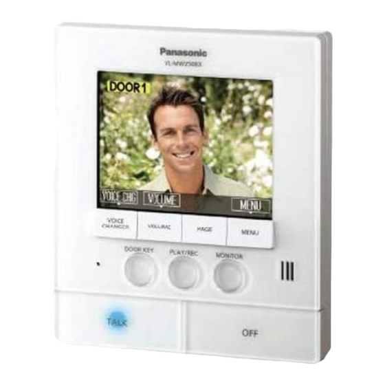
VL-SW250BX VL-MW250BX
Model No.
For door station and main monitor station
LPlease read this Installation Guide before installing the unit and save for future reference.
LPlease read this Installation Guide carefully, and install the unit safely and correctly by
following the instructions. Panasonic assumes no responsibility for injuries or property
damage resulting from failures arising out of improper installation or operation inconsistent
with both the Installation Guide and Operating Instructions.
LPlease confi rm the wiring schematic diagram in this Installation Guide when you increase
an optional equipment
.
Included accessories for installation
For the door station
LWood screws ..................2
(3.8 mm × 20 mm)
L Attached to the bag the door station
is in.
For your safety
To prevent severe injury and loss of life/property, read this section carefully before using the
unit to ensure proper and safe operation of your unit.
WARNING
LTo reduce the risk of electric shock, do not disassemble this unit. Refer servicing to an
authorized service center when service is required. Opening or removing covers may
expose you to dangerous voltages or other risks. Incorrect reassembly can cause electric
shock when the unit is subsequently used.
LDo not make any wiring connections when the power supply is turned on.
LNever install wiring during a lightning storm.
LDo not overload power outlets and extension cords. This can result in the risk of fi re or
electric shock.
LDo not install the main monitor station in the following places:
– Places where the main monitor station may be splashed with water or chemicals.
– Places where there is a high concentration of dust, or high humidity.
LWhen existing chime wires are used, it is possible that they contain AC voltage. Electric
shock or unit damage could result. Contact an authorized service center.
CAUTION
LInstall the unit securely adhering to the instructions in this guide to prevent it from falling off
the wall. Avoid installing onto low-strength walls, such as gypsum board, ALC (autoclaved
lightweight concrete), concrete block, or veneer (less than 18 mm thick) walls.
LIf the wiring is outdoors, use a protection tube or a surge protector.
LIf the wiring is underground, do not make any connections underground.
LIf the wiring is underground, use a protection tube.
1-62, 4-chome, Minoshima, Hakata-ku, Fukuoka 812-8531, Japan
© Panasonic System Networks Co., Ltd. 2010
VL-V566BX
VL-MW250BX
VL-V566BX is described as "Door
station" and VL-MW250BX is described
as "Main monitor station" in this guide.
For the main monitor station
LMounting bracket ............1
LWood screws ..................2
(4 mm × 16 mm)
L Attached to the rear of the main
monitor station.
PNQW2395ZA SV0910SN0
Before installation
To avoid malfunction or communication disturbances, do not install either the door station or the
main monitor station in the following locations:
– Places where vibration or any other kind of impact occurs.
– Places where echoing is frequent.
– Places near a high concentration of dust, hydrogen sulfi de, ammonia, sulfur, or noxious fumes.
– Within 2 m of a TV, microwave, personal computer, air conditioner or any other electrical device.
Installation position of the door station and camera range
N
Views when the camera is facing forwards at 0° (default).
LExample: Installation height is 1450 mm (standard position).
Side view
1810 mm
Center of
the door
station
66°
650 mm
Image
range
1450 mm
1160 mm
500 mm
The camera angle can be adjusted using the camera angle control lever on the rear of the door
station (step 3, "Installing the door station"), so that the image range can be changed.
N
Side view when the camera is installed
lower than the standard position, and
facing upwards at 15°.
LExample: Installation height is 1100 mm.
1690 mm
Center of
710 mm
the door
66°
station
Image
range
1100 mm
980 mm
500 mm
*
1
If the camera points 15° upwards, the left or right angle is less than 7°.
Note:
LThe measurements and angles are for reference purposes and may vary depending on the
environment.
LIf a strong light is shining on the door station, the visitor's face may not be distinguishable.
Do not place the door station in the following locations.
– Where most of the background is the sky.
– Where the background is a white wall, and direct sunlight will refl ect off it.
– Where direct sunlight will shine on the door station.
LDo not place the door station in the locations where echoing occurs, causing the unit to beep
frequently.
L Make sure the rear of the door station is not subject to water.
Standard installation position of the main monitor station
Place the main monitor station in a location that your eyes are the same height as the center of the
display.
If a position of installation for the main monitor station is specifi ed
Install the mounting bracket to one of the following positions.
Position of installation for the main monitor station
Note:
LThis unit is using an electric wave frequency of 2.4 GHz. Read "For best performance" in the
Operating Instructions.
LIn areas surrounded by a high electrical fi eld, disturbances may occur in the main monitor
station's image or sound.
LBe sure to install the main monitor station more than 5 m away from the door station.
LDo not place any objects within 20 cm of the main monitor station. This may cause
communication errors or malfunction.
LDo not install the main monitor station inside a wall.
LDo not install the main monitor station in places where it will be affected by extremely high-
frequency radio waves (near broadcasting antennas etc.). This may cause the display to fl icker
or an interrupting noise to occur.
If you change to the main monitor station from chime, bell or buzzer
Existing wires (e.g. chime, bell or buzzer) may connect to power supplies (AC 100 – 240 V or 24 V).
If you connect the main monitor station through such existing wires, electric shock or unit damage
may occur. Contact the dealer where you purchased.
Top view
Image range:
960 mm
87°
500 mm
N
Top view when the camera is facing
left or right at 15° *
.
1
LExample: Camera angle faces left 15°.
Image range:
1080 mm
810 mm
270 mm
87°
500 mm
Advertisement

Related Manuals for Panasonic VL-SW250BX


Summary of Contents for Panasonic VL-SW250BX
-
Page 1: Before Installation
LPlease read this Installation Guide carefully, and install the unit safely and correctly by 960 mm following the instructions. Panasonic assumes no responsibility for injuries or property damage resulting from failures arising out of improper installation or operation inconsistent with both the Installation Guide and Operating Instructions. -
Page 2: Installing The Door Station
Installing the door station Installing the main monitor station Important: Attach the mounting bracket to the wall securely using the wood screws (4 mm x 16 mm). LOn the bottom surface of the door station, there are holes to allow water to drain. Do not cover them up when installing. -
Page 3: Wiring Schematic Diagram
Wiring schematic diagram Set up correctly according to the following wiring schematic diagrams and “Wire type and distance”. Optional equipment (Refer to pages 42-43 in the Operating Instructions.) Door station 1 * Door station 2 (Non polar) (Non polar) You can also connect an optional lobby station for apartment PBX*...