Table of Contents
Advertisement
Quick Links
R This guide is for use with the above 2 models.
R The Installation Guide in Indonesian can be accessed from the following site:
https://panasonic.net/cns/pcc/support/intercom/sw274
R Door station is described as "doorphone" and Main monitor station is described as "main
monitor" in this guide.
R In this guide, the suffix of each model number (e.g., the "BX" in "VL-SW274BX") is omitted
unless necessary.
Note to the installer
R Before attempting to connect or operate this product, please read the label on the rear of
the doorphone and the main monitor/extension monitor.
R Please read this guide carefully, and install the product safely and correctly by following
the instructions. Carefully read the information found in the section titled "For your
safety" in particular.
R Only use attachments/accessories specified by the manufacturer.
R The installation shall be carried out in accordance with all applicable installation rules.
R To the maximum extent permitted by law, Panasonic assumes no responsibility for
injuries or property damage resulting from failures arising out of improper installation or
operation inconsistent with this document.
R After installation, make sure to leave this guide with the customer.
Model Name
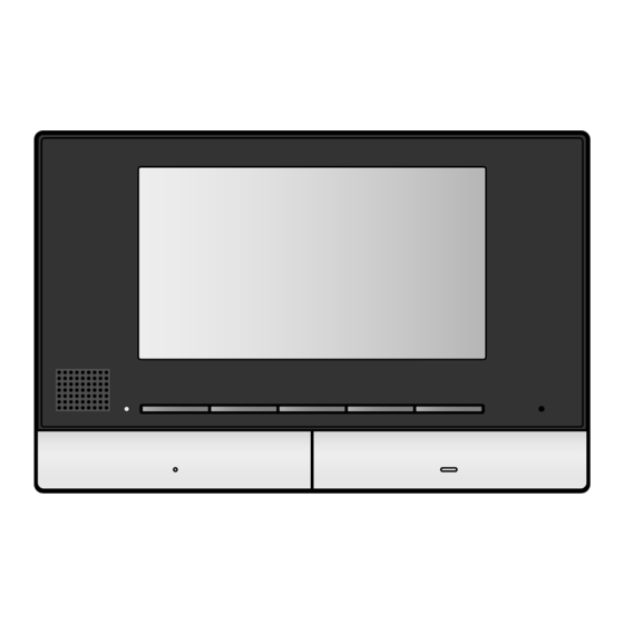
Wireless Video Intercom System
Main Monitor Station
VL-V522L
Door station
Installation Guide
VL-MW274
Main monitor station
Model No.
Model No.
VL-SW274
VL-MW274
Advertisement
Table of Contents

Related Manuals for Panasonic VL-MW274


Summary of Contents for Panasonic VL-MW274
- Page 1 R The installation shall be carried out in accordance with all applicable installation rules. R To the maximum extent permitted by law, Panasonic assumes no responsibility for injuries or property damage resulting from failures arising out of improper installation or operation inconsistent with this document.
-
Page 2: For Your Safety
– Places where there is a high For your safety concentration of dust, or high humidity. To prevent severe injury and loss of life/ RDo not perform any actions (such as property, read this section carefully fabricating, twisting, stretching, before using the product to ensure bundling, forcibly bending, damaging, proper and safe operation of your altering, exposing to heat sources, or... -
Page 3: Preventing Injury
Preventing injury walls, such as gypsum board, ALC (autoclaved lightweight concrete), Install the product securely adhering concrete block, or veneer (less than to the instructions in this guide to 18 mm thick) walls. prevent it from falling off the wall. Avoid installing onto low-strength Supplied accessories for installation For the doorphone... -
Page 4: Precautions For Installation
Precautions for installation To avoid malfunction or communication disturbances, do not install the doorphone or the main monitor/ extension monitor in the following locations: – Places where vibration or any other kind of impact occurs. – Places where echoing is frequent. –... -
Page 5: Wiring Schematic Diagram
Wiring schematic diagram Set up correctly according to the following wiring schematic diagram and "Wire type and length". R For information, such as order numbers, about optional devices that can be connected to, refer to the "Additional/replacement accessories" section in the Operating Instructions. DOORPHONE 1 DOORPHONE 2 You can also connect an... - Page 6 Wire type and length Wire type Wiring run Diameter Length (Max.) ø 0.65 mm 22 AWG 100 m Doorphone – Main monitor – ø 1.0 mm 18 AWG 130 m Extension monitor ø 0.5 mm CAT 5 50 m According to the Main monitor –...
- Page 7 Connecting an optional lobby station VL-V591 Lobby station MAIN MONITOR <Rear view> Ml-1 Ml-2 MO-1 MO-2 MO-3 MO-4 MO-5 MO-6 NP: Non-polarised <Be sure to perform the following to ensure proper operation> R Connecting an optional VL-V591 lobby station – Connect terminal D1/D2 on the main monitor with terminal D1/D2 on the lobby station. –...
-
Page 8: Doorphone Installation Position
Doorphone installation position Installation position of the doorphone and camera range Views when the camera is facing forwards at 0° (default). R Example: Installation height is 1450 mm (standard position). (Units: mm) A view when looking from above A Image range B Approx. 66° C Centre of doorphone D Approx. 1450 E Approx. 500 F Approx. -
Page 9: Installing The Doorphone
Attach the mounting base (A) to the wall Installing the doorphone securely using the wood screws (B) (accessory). Important: R Install the mounting base on a vertical flat R On the bottom surface of the doorphone and the wall. mounting base, there are holes to allow water to R Before drilling, refer to “Precautions for drain. - Page 10 Examples of camera angle B Mount the doorphone to the mounting base. Fasten the screw, then close the Facing forwards Facing upwards screw cover (C). Facing left Facing upper left R The angle can also be adjusted to the right or upper right.
- Page 11 Main monitor/extension Installing the main monitor/ monitor installation position extension monitor About the installation position of the main Attach the mounting bracket (A) to the wall monitor/extension monitor and mounting securely. bracket R Install the mounting bracket on a vertical flat R Place the main monitor/extension monitor in a wall (B).
- Page 12 Important: Do not connect the power cable. (Damage may occur.) Mount the main monitor/extension monitor to the mounting bracket. 3-1 Line up the tab on the bottom of the bracket with the groove on the main monitor/ extension monitor. 3-2 Line up the tab on the top of the bracket with the groove on the main monitor/extension monitor, and push the main monitor/extension monitor down until it is secure.
- Page 13 Notes...
- Page 14 Notes...
- Page 15 Notes...
- Page 16 1006, Oaza Kadoma, Kadoma-shi, Osaka 571-8501, Japan http://www.panasonic.com © Panasonic Corporation 2017 PNQX8614ZA C0917MM0...