Panasonic VL-V900 Installation Manual
Video intercom system
Hide thumbs
Also See for VL-V900:
- Installation and operating instructions manual (68 pages) ,
- Quick reference manual (2 pages) ,
- Manual (2 pages)
Table of Contents
Advertisement
Quick Links
Advertisement
Table of Contents

Related Manuals for Panasonic VL-V900


Summary of Contents for Panasonic VL-V900
- Page 1 2016 Video Intercom INSTALLATION GUIDE...
-
Page 2: Table Of Contents
......P31 2-2. Lobby Station (VL-V900) .... - Page 3 10 Appendix 5-11. Restarting a device ..P101 10-1. VL-V900 Series (Specifications) ... P109 10-2. Installing the Power Supply Unit (VL-PS240) 6. Operation .
- Page 4 Why Choose a Panasonic Video Intercom System?
-
Page 5: Why Panasonic
Why Panasonic? 1-1. Why Panasonic Video Intercom for Apartment Complexes Features Proposed System Solutions Large Apartment Systems Monitor Choices with the Panasonic PBX system and security cameras Monitors can be chosen from among 3 Capable of handling large apartment types to suite customer needs. An exclusive buildings of up to 560 households. -
Page 6: Role/Features/Installation
Role/ Features / Installation... - Page 7 Control Box Extension Box VL-V700 18units (with Extension Box) VL-V703 560 units Main Monitor Distribution Box VL-V701 Lobby Station Main Monitor VL-V900 Lift Controller VL-MVN511/MW251/MV26 VL-V702 Other Connectable Devices Electric Locks 1 unit 1 unit Terminals 4 units Security Camera...
-
Page 8: Video Intercom For Apartment Complexes
Up to 560 room units total Monitor Lobby Station or Security Camera System Security Camera Main Monitor VL-MVN511/MW251/ E-LOCK Lobby Station E-LOCK MV26 VL-V900 Control Box Distribution Box VL-V700 VL-V701 Save Images & Logs Lift Controller LIFT VL-V702 Entrance Guard... -
Page 9: Lobby Station (Vl-V900)
Role/ Features / Installation 2-2. Lobby Station : VL-V900 Doorphone for the public entrance of housing complexes Role of the VL-V900 Destination display, calling, conversation, and electric lock Features -4.3 inch monochrome display (white backlit LCD -Wide angle camera (Horizontally:170˚, vertically:115˚) - Page 10 Role/ Features / Installation 2-2. Lobby Station : VL-V900 (Features) Features View Angles Wide Zoom and Pan Tilt Zoom View(Select 9 position) Wide View Position Guide - Change camera view Wide Zoom and Pan Tilt - Change the view by MENU ‐...
- Page 11 Role/ Features / Installation 2-2. Lobby Station : VL-V900 (Installing the Lobby Station) Step 1 Step 2 Open the knockout holes of the flush mount box, Make a hole in the wall for the flush mount box. and then pass all necessary cables and wires...
- Page 12 Role/ Features / Installation Installing the Lobby Station 2-2. Lobby Station : VL-V900 ( Image range 2,300 mm Connect the wires and cables to the lobby station. Step 4 Approx. 115° Cable release button for DC power supply cable Centre of...
-
Page 13: Control Box (Vl-V700)
Role/ Features / Installation 2-3. Control Box : VL-V700 Role of the VL-V700 Insert Here POWER ACCESS Category Meaning (GREEN (RED) SD card Normal Idle operation Call or monitoring in progress Control Box Accessing SD card Flashing quickly System setup PC programming in progress PC connection check in progress Error Duplicate distribution box number found... - Page 14 Role/ Features / Installation 2-3. Control Box : VL-V700 POWER ACCESS Category Meaning (GREEN (RED) Normal Role of the VL-V700 Idle operation Call or monitoring in progress Accessing SD card Flashing quickly System setup PC programming in progress Device for controlling the entire system PC connection check in progress Error Duplicate distribution box number found...
-
Page 15: Distribution Box & Repeater (Vl-V701)
Role/ Features / Installation 2-4. Distribution Box & Repeater : VL-V701 Role of the VL-V701 POWER ACCESS Category Meaning (GREEN) (RED) Normal operation Idle Call or monitoring in progress Distribution Box Error DIP switch 8 is in the "on" position Flashing slowly Room unit (up to 20) Two or more DIP switches are in... - Page 16 Role/ Features / Installation 2-4. Distribution Box & Repeater : VL-V701 POWER ACCESS Category Meaning (GREEN) (RED) Role of the VL-V701 Normal operation Idle Call or monitoring in progress Functions as a distribution box or repeater. Error DIP switch 8 is in the "on" position Flashing slowly The function can be switched ON/OFF with the Repeater switch.
-
Page 17: Lift Controller (Vl-V702)
Role/ Features / Installation 2-5. Lift Controller : VL-V702 Role of the VL-V702 Example Function Controlling the destination (floor) of visitors by linking with the lift and lift control box Accept For visitors Visitor comes and call Room 302 Residents 302 push the button The Lift controller accepts And answer only 3rd Floor. -
Page 18: Supported Control Methods Of Vl-V702
Door Open Door Open Operation Environment : -10℃ to 50℃ Supported control methods -1:1 control (Relay Signaling) / Binary control Panasonic -Normally Open / Normally Close (1F) (2F) (3F) (18F) (19F) - Page 19 Role/ Features / Installation 2-5. Lift Controller : VL-V702 POWER ACCESS Category Meaning (GREEN) (RED) Role of the VL-V702 Normal Idle operation Call or monitoring in progress Controlling the destination of lifts Error DIP switch 6 or 7 is in the "on" position Flashing slowly Controlling the destination (floor) of visitors Two or more DIP switches are in the...
-
Page 20: Extension Box (Vl-V702)
Role/ Features / Installation 2-6. Extension Box : VL-V703 Role of the VL-V703 Extend the number of Lobby Station. ( Original 3pcs. Max. Up to 18pcs. ) POWER ACCESS Operation Environment : -10℃ to 50℃ Category Meaning (GREEN) (RED) Normal Idle operation Call in progress... -
Page 21: Room Unit (Main Monitor) (Vl-Mvn511)
Role/ Features / Installation 2-7. Room Unit (Main Monitor) : VL-MVN511 APARTMENT MODE / HOUSE MODE Sales Point 1. Smart phone connectivity Easy setup, Easy installation with a Wi-Fi connection 2. Auto picture recording function Up to 50 visitors, 8 shots per visitor can be recorded 3. - Page 22 Role/ Features / Installation 2-7. Room Unit (Main Monitor) : VL-MVN511 Rea Side D1,D2 : Distribution Box(VL-V701) D3,D4 : Door Station Commercially Sensor or Button (Support Emergency call) Commercially Sensor or Button (Support Door Bell)
-
Page 23: Room Unit (Main Monitor) (Vl-Mw251)
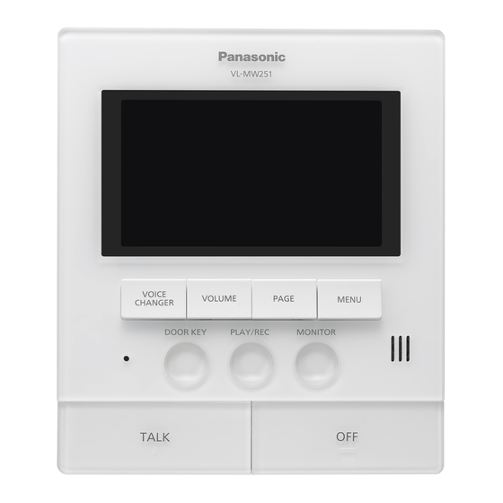
Role/ Features / Installation 2-8. Room Unit (Main Monitor) : VL-MW251 APARTMENT MODE / HOUSE MODE Sales Point 1. Wireless Sub Monitor Answer visitors anywhere at home. Support additional sub monitors up to 4. 2. Picture recording function 8 pictures / 1 session, max 50 sessions Auto picture recording 3. -
Page 24: Room Unit (Main Monitor) (Vl-Mv26)
Role/ Features / Installation 2-11. Room Unit (Main Monitor) : VL-MV26 APARTMENT MODE Sales Point 1. Colour LCD monitor 3.5 inch color LCD provides a clear image. On screen UI helps the user to easily use. 2. Picture recording function 1 pictures / 1 session, max 30 sessions Auto picture recording 3. -
Page 25: Room Unit (Main Monitor) Lineup
Role/ Features / Installation 2-10. Room Unit (Main Monitor) Lineup VL-V900 - VL-MVN511 series VL-V900 - VL-MW251 series VL-V900 - VL-MV26 series ‘2016 release option option Free App Display 5-inch, wide colour 5 inch, wide colour 3.5-inch, colour Picture recording... -
Page 26: Apartment Mode Or Housing Mode
Role/ Features / Installation 2-12. How to select the Apartment mode or Housing mode Image of Setup tool Default is the House mode. But no need to change the mode. When connect to the large apartment system and run the “Connection Check” by Setup tool, it automatically changes to Apartment mode. Confirmation of mode: Just as keep hold three kind of button, and turn on the power. -
Page 27: Wiring
Wiring... -
Page 28: Basic System Example
Wiring 3-1. Basic System Example Main Monitor Main Monitor Lobby Station 1 unit Control Box 1 unit Distribution Box 1 units Main Monitor 20 units Lobby Station Control Distribution VL-V701 VL-V900 VL-V700 Room Units (up to 20) System Room Entrance... -
Page 29: Basic System Configuration
Wiring 3-2. Basic System Configuration(Rear Side) Basic system example Room unit (up to 20) Main Monitor Door Station Lobby Station (1) Control Box (1) Distribution Box (1) 2wire 2wire x 2 2wire MVN511 MW251 Power Supply Unit Power Supply Unit Power Supply Unit MV26... -
Page 30: Large System Example
3-3. Large system example Lobby Station 3 units Control Box 1 unit 4 branches x 7 series connections x 20 dividers = 560 units Distribution Box 28 units Main Monitor 560 units Distribution Lobby Station VL-V701 VL-V900 Control Box VL-V700... - Page 31 18 units Extension Box 3 units 4 branches x 7 series connections x 20 dividers = 560 units Control Box 1 unit Distribution Box 28 units Main Monitor 560 units Distribution VL-V701 Lobby Station VL-V900 Control Box Extension Box VL-V703 VL-V700...
-
Page 32: Large System Configuration
Wiring 3-4. Large System Configuration (Rear Side) Distribution Box(1-2) Distribution Box(1-1) Lobby Station (1) Control Box (1) Room unit (up to 20) Main Monitor Door Station Power Supply Unit Power Supply Unit Power Supply Unit Power Supply Unit Power Supply Unit Power Supply Unit Power Supply Unit Power Supply Unit... -
Page 33: Cable Information
Wiring 3-5. Cable Information Uses PE (polyethylene)-insulated PVC or PE jacket 2C cable. ∅ 0.65 mm NP : Non-Polarized Telephone Cable Station Wire Diameter of Wire ∅ 0.65 mm / 22 AWG ∅ 1.20 mm / 17 AWG ANNEALED COPPER POLYETHYLENE POLYVINYL CONDUCTOR... -
Page 34: Wiring Type And Length
Wiring 3-6. Wiring type and length Wiring run Wire diameter Max. length 0.65 mm (22 AWG) approx. 100 m Control box <--> Lobby station 1.2 mm (17 AWG) approx. 200 m 0.65 mm (22 AWG) approx. 100 m Distribution mode Control box <-->... -
Page 35: Distance / How To Use Repeater
1.20mm : 200m 1.20mm : 200m 1.20mm : 200m Case1 Distribution Box The Farthest Monitor VL-V701 Control Box VL-V700 Lobby Station VL-V900 The Farthest V701 Case2 (usage of V701 Distribution Box The Farthest Monitor Repeater) (Repeater Mode) VL-V701 Control Box... - Page 36 Wiring 3-7. Distance (CAT6-cable) If power supply is set near the Distribution Box Distribution Box If you use CAT6 Cable instead of 2wire cable… Main Monitor VL-V701 1 pair x 2 : Signal cable 1 pair x 2 : Power cable Power Supply of Main Monitor 1 pair x 2: 110m...
-
Page 37: Distribution Box Switch Settings
Wiring 3-8. Distribution Box switch settings (How to set switch) Repeater Termination switch switch VL-V701 Switch setting DIP switches Repeater Termination switch switch Each branch line support 1 2 3 4 5 6 7 8 (OFF) (ON) up to One repeater. DIP switches DIP switches Repeaterswitch... -
Page 38: Lift Controller: Vl-V702
Wiring 3-9. Lift Controller : VL-V702 Control box Distribution box “302” VL-V700 VL-V701 Accept Accept Door Open Door Open Panasonic (1F) (2F) (3F) (18F) (19F) Lift Controller VL-V702 Only Relay #4(3F) will be active. For visitors Lift Control System Lift... - Page 39 Wiring 3-9. Lift Controller : VL-V702 Optional Input ports Lift system have optional input ports to integrate with other system. (ex. Video Intercom, Access control) Lift Controller These input ports may be installed at the top or bottom of lift system. In order for the function to work, settings need to be confirmed in advance with the lift manufacturer.
-
Page 40: Lift Controller Settings (Relay Control)
Wiring 3-10. Lift Controller settings (Relay control) Up to 3 Lift 3 branches x 5 lift controllers Up to 100 floor per lift (Up to 20 floor per lift controller) Control Box Lift Controller Lift Controller Lift Controller 79 F 79 F 79 F Lobby Station... - Page 41 Lift Controller settings (Up to 6 lifts) Up to 6 Lifts By connecting one branch per two lift, you can integrate up to 6 lifts. 3 branch x 2 lift controller x 2 lift systems. It can support up to 40 floor per lift. Control Box Branch3 Branch2...
-
Page 42: Lift Controller Configuration (Relay Control)
Wiring 3-11. Lift Controller Configuration (Relay control) Control Box(1) Distribution Room unit (up to 20) Lobby Station(1) Box(1) Main monitor Door Station Lift Controller(2-1) Lift Controller(2-5) Power Supply Unit Power Supply Unit Power Supply Unit Power Supply Unit Power Supply Unit Power Supply Unit Power Supply Unit Lift Controller(1-1) -
Page 43: Lift Controller / How To Set Dip Switch(Relay Control)
Wiring 3-12. Lift Controller / How to set DIP switch(Relay control) DIP switch Floors 80 - 99 79 F 79 F 79 F DIP switch Floors 69 F 69 F 69 F 60 - 79 60 F 60 F 60 F 59 F 59 F 59 F... -
Page 44: Lift Controller Configuration (Binary Control)
Wiring 3-13. Lift Controller Configuration (Binary control) Control Box Lift Controller Lift Controller Lift Controller 99 F 99 F 99 F Lobby Station Setup tool Port of Lift Controller Floor 99 F 100 98 F 97 F Lift-3 Lift-2 Lift-2 Lift-3 Lift-1... -
Page 45: Integration
Integration... -
Page 46: Pbx & Terminal (Example Of Configration)
Distribution Box Control Box VL-V701 VL-V700 Main Monitor Lobby Station Setting by PC tool VL-MVN511/MW251/ VL-V900 Telephone cable - Register up to 4 Extension No MV26 (RJ-11) - Select each terminal name from 15 choices Extension No: 100 Terminal 1... - Page 47 (No 101) VL-V701 VL-V700 Main Monitor Lobby Station Setting by PC tool VL-MVN511/MW251/ Select from description VL-V900 Telephone cable - Register up to 4 Extension No MV26 using by PC tool (RJ-11) - Select each terminal name from 15 choices Description...
- Page 48 Room System Entrance Distribution Box Control Box VL-V701 VL-V700 Main Monitor VL-MVN511/MW251/ MV26 Lobby Station VL-V900 Room Terminal 1 Named : Reception Main Monitor VL-MVN511/MW251/ MV26 Room mode Room Reception Reception mode Switching the mode (Room mode / Reception mode)
- Page 49 Control Box VL-V701 VL-V700 Emergency call Sensor Or Button Main Monitor Lobby Station VL-MVN511 VL-V900 Terminal 1 Extension No: 101 Named : Reception Terminal 2 Extension No: 102 Named : Gate Terminal 3 Named: Security Office Extension No: 103 Emergency Talk mode...
- Page 50 Distribution Box Main Monitor VL-V700 VL-V701 Analogue VL-MVN511/MW251/ Lobby Station Security Camera MV26 VL-V900 (NTSC/PAL) Setting by PC tool -Select each security camera name from 15 choices Camera 2 Named: PARKING The Lobby and Security camera are both selectable Guard...
- Page 51 Integration 4-2. Connecting to analogue security cameras & Monitor Uses ・ 1 camera can be connected to each lobby station. ・ 1 Monitor can be connected to Control Box Gate(CCTV) Gym/Pool(CCTV) Lobby Security(Monitor)
-
Page 52: System Condition And Limitations
Integration 4-3. System condition and Limitations Monitoring General Call Emergency call ( Lobby to Main monitor Lobby1 Main monitor to Terminal, etc.) Monitor Monitor Monitor (#101) (#102) (#103) Emergency call Main Monitor General Call General Call General Call (#101) ↓ Lobby1 Lobby2 Terminal#1... -
Page 53: Access Control & E-Locks
Integration 4-4. Access Control & E-Lock System Entrance Room Control Box Distribution Box Main Monitor VL-V700 VL-V701 Access control Lobby Station VL-MVN511/MW251/ MV26 VL-V900 Electrical Lock... - Page 54 Integration 4-4. Access Control & E-Lock configuration Access Control & E-Lock Access Control, E-Lock & Lobby Station 2 (N/P) 2 (N/P) Electrical Electrical Lock Lock V900 Switch Switch (Inside) (Inside) K-OUT K-OUT K-IN 2 (N/P) POWER SUPPLY UNIT K-IN Access Control Access Control /Card Reader /Card Reader...
- Page 55 Integration 4-4. Access Control & E-Lock Uses (How to open E-Lock) 1. Card Key (Outside) 2. Switch (Inside) #If integrate Access Control # If integrate Access Control Switch (Inside) Card Reader (Outside) 3. Input Pin cord (Outside) 4. Room Monitor (In Room) Push Door Key Button Lobby Station...
-
Page 56: Recording By Sd-Card
-- If image recorded maximum , after that old ones will be overwritten. Lobby Station IMG:999_0100(100%) VL-V900 -- If SD memory is full, the system log will be stopped and alert message will be displayed on the external Monitor. 1 pictures / 1 session VGA(640 ×... -
Page 57: Setup Tool
Setup Tool... - Page 58 Setup Tool 5-1. Update the software version using a SD-Card (VL-V700) Server* http://panasonic.net/pcc/support/intercom/v900 (1) Back up the setting data. (5) Keep pressing the Function switch After Updating, the setting data will be delated. until the LEDs are flashing quickly. So before updating, you should download After that release the switch.
-
Page 59: Programing
5.1.2. PC programming PC programming allows you to use a computer and the Panasonic Large Apartment System Setup Tool to create and edit system data while offline, and then upload the data to the system while on-site. -
Page 60: How To Setup
No. 304 Port5 Port6 Port7 Port8 No. 201 No. 202 No. 203 No. 204 Port1 Port2 Port3 Port4 Port1 No. 101 No. 102 No. 103 No. 104 Port5 Port6 Lobby Station Control Box Distribution Box Port7 Port8 VL-V900 VL-V700 VL-V701... - Page 61 Connect the PC vis USB and upload the date drawing. to the Control Box and Lobby from setup tool. Lobby Station Control Box VL-V900 VL-V700 Drawing 3. Wiring all monitors based on the drawing 4. Calling from Lobby to each room and and upload (set) the date from tool.
- Page 62 Port? Port? Port? No. 201 No. 202 No. 203 No. 204 Port? Port? Port? Port? Port1 Port? ? No. 101 No. 102 No. 103 No. 104 Port? Port8 Port? Lobby Station Control Box Distribution Box Port? Port? VL-V900 VL-V700 VL-V701...
- Page 63 Setup Tool 5-2-1. How to Setup <Situation2> If you don’t know where the each cable connect to. 1. Set the Apartment mode and room number 2. Wiring the Control Box, Distribution Box and Monitor. of each Room monitor. Send the each room programing date to the Control Box.
- Page 64 Setup Tool 5-2-1. How to Setup <Situation3> If you change one room monitor in the existing system. 2. On the PC setup tool 1. Change to the new Room Monitor select the back up date folder and then select the existing files. No.
-
Page 65: Setup Tool Overview
Setup Tool 5-3. Setup tool overview The setup tool is organized into the following sections. Control Box VL-V700 (1) Select folder Allows you to select the folder where you want to save your configuration files. Configuration files are saved in CSV format. (2) Prepare the data Allows you to choose whether you want to create new configuration files, use existing configuration files, or... -
Page 66: Setup Tool (Existing Configuration File )
Setup Tool 5-3. Setup tool ( Create new configuration file ) To create NEW configuration file Step 1 Select folder Step 2 Click Step 3 Click The paths of each configuration file Step 4 are displayed in the [Load and edit the data] section. -
Page 67: Setup Tool
Setup Tool 5-3. Setup tool ( Existing configuration file ) To existing configuration file Step 1 Select folder Step 2 Click For [Room settings] for lobby stations 1–3 (1) Click to open the configuration file. (2) Change the values in the appropriate p.xx columns. - Page 68 Setup Tool 5-3. Setup tool ( Download the data that is saved in the system’s devices ) To download from devices Step 1 Select folder Step 2 Turn on the checkboxes for the desired devices listed under [Download the data from]. Step 3 Click [Note] Before download from devices...
-
Page 69: Control Box - Room Settings
Setup Tool 5-4. Control Box – Room settings Parameter Description Default Room No. Determines the room number of the main monitor connected to the corresponding control box port, distribution box number, and distribution box port. (1–99999) Floor No. Determines the floor number setting of the corresponding room number. -
Page 70: Control Box - General Settings
Setup Tool 5-5. Control Box – General settings Parameter Description Default Monitor Time Out Determines the amount of time that passes when watching camera images before the standby screen is displayed. (180 SEC) [0]: 180 SEC, [1]:90 SEC, [2]:60 SEC, [3] :30 SEC Talk Time Out Determines the amount of time that passes when talking before the standby screen is displayed. -
Page 71: Lobby Station 1-3 - Room Settings
Setup Tool 5-6. Lobby Station 1-3 ― Room settings Parameter Description Default Room No. Determines the room number. (0–99999) Resident Name Determines the resident name for the corresponding room number. (20 characters max., uppercase letters only) -
Page 72: Lobby Station 1-3 - General Settings
Setup Tool 5-7. Lobby Station 1-3 ― General settings Parameter Description Default Door Key Open Time Determines the amount of time the door stays open. If 5 SEC set to 0 s, the door cannot be opened. (0–20 SEC) Door Key Out Signal Determines whether the signal sent to the electric lock is a closed signal (i.e., the signal is normally open) or an open signal (i.e., the signal is normally closed). -
Page 73: Lobby Station Programing
Setup Tool 5-8. Lobby station programing You can use a lobby station to configure various system settings. Register the lobby station - If you have already registered the lobby station, skip this step. 1. Press 【#】 → enter the access code 【 】... -
Page 74: Telephone Programming
Setup Tool 5-9. Telephone programming Use this procedure to configure the following settings. – The extension numbers of the PBX that will be used as terminals 1–4 and the emergency terminal – The names assigned to terminals 1–4 – Whether terminals 1–4 are used as a reception terminal or not 5. -
Page 75: Main Monitor Programming
Setup Tool 5-10. Main monitor programming Use this procedures in this section to configure the following settings. Perform this procedure for each main monitor. – Set the main monitor to apartment mode – Set the room number – Set the floor number –... - Page 76 Setup Tool 5-10. Main monitor programming The VL-MW251 programming 1. Press and hold [ OFF ] , [ TALK ] , and [ MENU ] at the same time (3 buttons total). Continue to hold the buttons and perform the next step. 2.
-
Page 77: Restarting A Device
Setup Tool 5-11. Restarting a device You can restart the control box, distribution box, or lift controller by pressing its reset button ( ● VL-V900 VL-V700 Reset button Reset button VL-V701 Reset button VL-V703 VL-V702 Reset button Reset button... -
Page 78: Operation
Operation... -
Page 79: Lobby Station Operations
Operation 6-1. Lobby station operations 6.1.1 Calling a resident Entering a room number 1. Enter the resident’s room number. 2. Press [ ] to call. Searching by first letter of the name 1. Press [ * ] . 2. Use the keypad to enter the first letter of the resident’s name. - Press a key repeatedly to scroll through the letters assigned to that key. -
Page 80: Facility Staff Operations
Operation 6-2. Facility staff operations Facility staff can use an extension telephone of a PBX to perform a variety of operations. Operations available when not on a call 1. Dial the extension number assigned to the control box. 2. Enter the feature number according to the feature you want to operate. Feature number Assignment (room number) [ # ]... -
Page 81: Replace
Replace... -
Page 82: Replace From Cat-5E Cable (Ip System)
POWER Distribution Box VL-V701 Cat6 Cable POWER /1.2mm/0.65mm L2-Switch Lobby Station Lobby Station VL-V900 Control Box VL-V700 Lobby Station - Control Box - Distribution Box : New Cable (Cat-6/1.2mm/0.65mm) Distribution Box/DC Power Supply - Room Monitor : Existing Cable(Cat-5e/Power Cable) - Page 83 Replace Replace from Intercom system (PVC mesh cable) Distribution Box VL-V701 Control Box VL-V700 Cat6 Cable Lobby Station - Control Box : New Cable (Cat-6) Control Box - Distribution Box : New Cable (Cat-6) Distribution Box - Room Monitor : Exiting Cable(PVC cable less than 30m)
- Page 84 Replace Replace from Intercom system (mesh type PVC cable) Room 220V Continuously using the mesh type PVC wire using 2 wire (Existing cable is 7 wire) (less than 30m from Raiser) Lobby Raiser Exiting Fermax Lobby Station have camera. Back board will be also replaced soon But room monitor for new Lobby Station.
- Page 85 Replace 7-1. Replace from Cat-5e Cable (IP System) Room Power Cable Cat5E Cable Remove the Existing Room Monitor Attach the Custom Cover Connect the Cat5e and Power Cable (made by Sier) Raiser Power Supply PS240 Cat6 Cable Power Cable (to Control Box and Distribution Box) Cat5E Cable (to Each Room Monitor) Existing...
-
Page 86: Replace From Cat-5E Cable (Ip System/Poe-Switch)
PoE SW Distribution Box VL-V701 Cat6 Cable /1.2mm/0.65mm L2-Switch Lobby Station Lobby Station VL-V900 Control Box VL-V700 Lobby Station - Control Box : Existing Cable (Cat3)/New Cable Control Box - Distribution Box : New Cable (Cat-6/1.2mm/0.65mm Distribution Box/DC Power Supply - Room Monitor : Existing Cable(Cat-5e) -
Page 87: Replace From Cat-3(4Wire Cable) System
DC power PS240 Distribution Box VL-V701 Distribution Box VL-V701 Cat6 Cable /1.2mm/0.65mm Lobby Station VL-V900 Control Box VL-V700 Lobby Station Lobby Station - Control Box : Existing Cable (Cat3)/New Cable Control Box - Distribution Box : New Cable (Cat-6/1.2mm/0.65mm Distribution Box/DC Power Supply - Room Monitor : Existing Cable(Cat-5e)+New Cable... -
Page 88: Estimate
Estimate... -
Page 89: How To Make An Estimate Of The System
Estimate How to make an estimate of the system? Villa complex Multi Building High-rise Huge... - Page 90 Estimate How many distribution boxes are needed? 11 - 20 Rooms / Floor : Install one distribution box per each floor Distribution Distribution Distribution...
- Page 91 Estimate How many distribution boxes are needed? 7 - 10 Rooms / Floor : Install one distribution box per two floors Distribution Distribution...
- Page 92 Estimate How many distribution boxes are needed? Case study : 8 Rooms / Floor @ Indonesian project Distribution Distribution Control...
- Page 93 Estimate How many distribution boxes are needed? ~ 6 Rooms / Floor : Install one distribution box per three floors Distribution...
- Page 94 Estimate How many distribution boxes are needed? Case study : 6 Rooms / Floor @ Myanmar Project Distribution Control...
- Page 95 Estimate Main Monitor & Power Supply Attached Power Supply Unit VL - MVN511 DC:24V VL – MV26 DC:24V AC power directly. VL – MW251...
- Page 96 Estimate Where is Power supply unit installed? Supplied AC Power from each room 220V # Power supply unit of MV511 / MV26 is installed at room. 220V # MW251 is directly connected to AC 220V of room.
- Page 97 Estimate Where is Power supply installed? Install Power supply unis at Riser and DC output is wired to each monitor DC:24V DC:24V DC:24V 220V DC:24V DC:24V DC:24V 220V...
- Page 98 Estimate Where is Power supply installed? Install Power supply unis at Riser and DC output is wired with signal cable 220V 220V Cat3(0.65mm 4wire) Cat5e/Cat6 Cable Up to 70m...
- Page 99 Estimate How to support multi building? 4 tower 1 entrance Tower1 Tower2 Tower3 Tower4 Distribution 20units 20units 20units 20units Distribution Distribution 20units 20units 20units 20units 20units 20units 20units 20units Repeater Repeater 100m(φ0.65)/200m(φ1.2) Control...
- Page 100 Estimate How to support multi building? Case study : 3 tower 1 entrance @ Malaysia project Distribution Distribution Distribution Repeater Control Repeater...
- Page 101 Estimate How to support multi building? 8 tower 2 entrance Lobby for Tower1-4 Lobby for Tower1-4 Lobby for Tower5-8 Lobby for Tower5-8...
- Page 102 Estimate How to support more than 4 Lobby Station project? We will Launch Extension box “VL-V703” at the end of July.
- Page 103 Estimate How to support more than 4 Lobby Station project? High-rise building with 8 Lobby Stations Distribution Repeater Extension Control Repeater...
- Page 104 Estimate How to support the villa complex?
- Page 105 Estimate How to support the villa complex? Case study : 108 house gated community @ Malaysia project Distribution Distribution Repeater Control Outdoor cabinet Distribution Distribution Distribution Repeater Distribution Piping under the ground...
-
Page 106: Question For New Project And Replace Project
Question for new project and replace project Question Purpose Type of project Cond or villa / new or replace/ IP , analog or doesn’t matter Qty of Room How many room monitors? Qty of Floor/ How many distribution boxes? How many rooms per floor? Qty of Public Entrance How many Lobby Stations? Need Extension box? Qty of Guard Station... -
Page 107: Question For Replace Project
Question for replace project Question Purpose Existing system Compare with our product. (Brand and product number) And propose the benefit for after replacement Existing system diagram Check the possibility of replace by using existing cable (Wiring topology) -Signal cable, Power cable -length of each cable Existing type of cable Check the possibility of replace by using existing cable... -
Page 109: Appendix
Appendix... - Page 110 Appendix 10-1. Lobby Station : VL-V900 (Specifications) Power supply unit (VL-PS240) Power source 24 V DC, 0.2 A Standby: Approx. 1.9 W Power consumption During Operation: Approx. 4.5 W Dimensions (H x W x D) 373 x 179 x 2.5 mm (excluding sections embedded into the wall)
- Page 111 Appendix 10-2. Control Box : VL-V700 (Specifications) Power supply unit (VL-PS240) Power source 24 V DC, 0.2 A Power consumption Standby: Approx.3.5 W, During operation: Approx.3.7 W Dimensions (H x W x D) (Excluding protruding 108.5 x 210 x 52.5 mm sections) Weight 400 g...
- Page 112 Appendix 10-3. Control Box : VL-V700 (Specifications) Power supply unit (VL-PS240) Power source 24 V DC, 0.2 A Power consumption Standby: Approx.3.5 W, During operation: Approx.3.7 W Dimensions (H x W x D) (Excluding protruding 108.5 x 210 x 52.5 mm sections) Weight 400 g...
- Page 113 Appendix 10-4. Distribution Box : VL-V701 (Specifications) Power source Power supply unit (VL-PS240) 24 V DC, 0.1 A Power consumption (Distribution mode) Standby: Approx.1.2 W, During operation: Approx.2.0 W (Repeater mode) Standby: Approx.1.6 W During operation: Approx.1.8 W Dimensions (H x W x D) 108.5 x 210 x 52.5 mm (Excluding protruding sections) Weight...
- Page 114 Appendix 10-5. Lift Controller : VL-V702 (Specifications) Power source Power supply unit (VL-PS240) 24 V DC, 0.2 A Power consumption Standby: Approx. 0.4 W During operation: Approx. 4.4 W Dimensions (H x W x D) 210 x 108.5 x 52.5 mm (Excluding protruding sections) Weight 400 g...
- Page 115 Appendix 10-6. Extension Box : VL-V703 (Specifications) Power source Power supply unit (VL-PS240) 24 V DC, 0.2 A Power consumption Standby: Approx. 1.5W During operation: 1.3W Dimensions (H x W x D) 210 x 108.5 x 52.5 mm (Excluding protruding sections) Weight 400 g Operating environment...
- Page 116 Specifications 10-10. Room Unit (Main Monitor) Comparison chart ‘2016 release VL-MVN511 VL-MW251 VL-MV26 Power supply unit Power supply unit Power source (VL-PS240:220-240 V AC, 0.2 A, 50/60Hz ) 100-240 V AC, (50/60Hz) (VL-PS240:220-240 V AC, 0.2 A, 50/60Hz ) 24V DC, 0.5A T.B.D.
- Page 117 Appendix 10-1. Connecting wiring ( VL-V700: VL-V701: VL-V702: Control Box, Distribution Box, Lift Controller (1) (2) Wire release button Connection terminal Wires to/from other devices Cable release button for DC power supply cable DC cable from power supply unit...
-
Page 118: Installing The Power Supply Unit (Vl-Ps240)
Appendix Recommended torque: 10-2. Installing the Power Supply Unit (VL-PS240) – AC terminal: 0.4 N·m {4.1 kgf·cm} – DC terminal: 0.45 N·m {4.6 kgf·cm} How to connect the power cable (AC/DC) Step 3 Connect the AC/DC cable to the AC IN Connect the power supply unit and AC/DC cables. - Page 119 Appendix 10-2. Installing the Power Supply Unit (VL-PS240) Mounting on a DIN rail Follow the procedure in the order described below so that hook (1) is positioned at the bottom. 1. Hang the top hooks (2) on the DIN rail (3). 2.
-
Page 120: Expanded System Example
Appendix 10-3. Expanded system example Room Unit (up to 560) * Up to 20 (Monitor) x 7 (Distribution Box) x 4 (branches) Distribution Box (up to 28) Lobby Station * Up to 7 per 4 (up to 3) branches Security Camera E-Lock Control Box (1) Repeater Mode... - Page 122 Trademarks and registered trademarks - Wi-Fi is a trademark or registered trademark of Wi-Fi Alliance. iPhone and iPad are trademarks of Apple Inc., registered in the U.S. and other countries - Android is a trademark of Google Inc. • The actual product may vary slightly from photograph. •...