Panasonic VL-MVN511 Installation Manual
Hide thumbs
Also See for VL-MVN511:
- Installation manual (122 pages) ,
- Manual (2 pages) ,
- Quick manual (2 pages)
Table of Contents
Advertisement
Model Name
Model No.
R This guide is for use with the above 2 models.
R The VL-SVN511 models composition consists of VL-MVN511 and VL-V555.
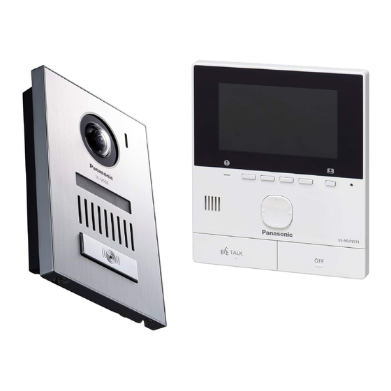
VL-MVN511
Main monitor station
R For VL-V555 users: Please read the areas related to the VL-V555 and also please refer to
the installation guide of the main monitor that the doorphone is connected to.
R Door station is described as "doorphone" and Main monitor station is described as "main
monitor" in this guide.
R In this guide, the suffix of each model number (e.g., the "BX" in "VL-SVN511BX") is omitted
unless necessary.
Note to the installer
R Before attempting to connect or operate this product, please read the label on the rear of
the doorphone and the main monitor.
R Please read this guide carefully, and install the product safely and correctly by following
the instructions. Carefully read the information found in the section titled "For your
safety" in particular.
R Only use attachments/accessories specified by the manufacturer.
R The installation shall be carried out in accordance with all applicable installation rules.
R Panasonic assumes no responsibility for injuries or property damage resulting from
failures arising out of improper installation or operation inconsistent with this guide.
Additionally, any resulting malfunction will not be covered under the warranty.
R After installation, make sure to leave this guide with the customer.
Video Intercom System
VL-SVN511 Series
VL-V555
Door station
Installation Guide
Door station
VL-V555
Advertisement
Table of Contents

Related Manuals for Panasonic VL-MVN511


Summary of Contents for Panasonic VL-MVN511
-
Page 1: Installation Guide
R Only use attachments/accessories specified by the manufacturer. R The installation shall be carried out in accordance with all applicable installation rules. R Panasonic assumes no responsibility for injuries or property damage resulting from failures arising out of improper installation or operation inconsistent with this guide. -
Page 2: For Your Safety
cause electric shock, short circuits, or fire. For your safety Contact an authorised service centre for repairs. R When existing chime wires are used, it is possible that they contain AC voltage. To prevent severe injury and loss of life/property, Contact an authorised service centre. -
Page 3: Supplied Accessories For Installation
Supplied accessories for installation For the doorphone *1, *4 Mounting base ´ 1 Screw ´ 4 Screw ´ 2 Name plate ´ 2 Hex wrench ´ 1 (4 mm ´ 12 mm) (3.8 mm ´ 20 mm) (incl. 1 spare) For the main monitor Relay box and related items Cable binder ´... -
Page 4: Precautions For Installation
Precautions for installation To avoid malfunction or communication disturbances, do not install the doorphone or the main monitor in the following locations: – Places where vibration or any other kind of impact occurs. – Places where echoing is frequent. – Places near a high concentration of dust, hydrogen sulphide, ammonia, sulphur, or noxious fumes. For the doorphone R If a strong light is shining on the doorphone, the visitor’s face may not be distinguishable. -
Page 5: Wiring Schematic Diagram
Wiring schematic diagram Set up correctly according to the following wiring schematic diagram and "Wire type and length". R For information, such as order numbers, about optional devices that can be connected to, refer to the "Additional/replacement accessories" section in the Operating Instructions. R For VL-V555 users: Refer to the wiring diagram of the Video Intercom device that VL-V555 is connected to. - Page 6 Wire type and length Wire type Wiring run Diameter Length (Max.) ø 0.65 mm 22 AWG 100 m Main monitor – Doorphone ø 1.0 mm 18 AWG 130 m (including lobby station) ø 0.5 mm CAT 5 50 m ø 0.65 mm 22 AWG 10 m Main monitor –...
- Page 7 n Connecting an optional lobby station (VL-SVN511AZ models only) Lobby station (VL-V590) MAIN MONITOR <Rear view> RELAY BOX <Rear view> Electric lock 30 V AC/ 24V DC Power supply NP: Non-polarised <Connecting an optional lobby station for apartment complexes> R Be sure to perform the following to ensure proper operation –...
-
Page 8: Doorphone Installation Position
Doorphone installation position Installation height and area visible by the camera lens (when connected to VL-SVN511 series) You can use the [Wide/Zoom settings] setting on the main monitor to select the area that is visible when a visitor calls; available settings are [Wide] and [Zoom]. (Default setting: [Wide]) R The following values are for when the doorphone is installed in the standard position (the centre of the doorphone’s height is approximately 1450 mm) and the visitor is approximately 500 mm away from the camera lens. - Page 9 Up and down Left and right (when looking from above) (Units: mm) (Units: mm) Left A Image range B Approx. 80° C Center of A Image range: Approx. 1200 B Approx. 500 doorphone D Approx. 1450 E Approx. 500 C Approx. 100° D Approx. 170° F Approx.
-
Page 10: Installing The Doorphone
When using mounting box (option): Installing the doorphone Model No. VL-MB554 Install the flush mounting box (A) in the Important: wall. R On the bottom surface of the doorphone and the mounting base, there are holes to allow water to drain. - Page 11 Connect the wires. When using mounting box (option): Loosen the screws. Push in the wires to the Model No. VL-MB554 terminal connectors (non-polar), then tighten Attach the doorphone to the flush the screws (A). mounting box. – Recommended torque: 0.5 N·m {5.1 kgf·cm} –...
-
Page 12: Installing The Power Supply
Power supply unit (with cable covers Installing the power supply removed) Top view Bottom view unit (VL-SVN511EX/FX models only) About the installation location R The device must be installed inside an electrical panel or cabinet. R A readily accessible disconnect device shall be L AC cable binder hole incorporated external to the equipment. -
Page 13: Installing The Power Supply Unit (Vl-Svn511Az Models Only)
Power supply unit (with cable cover removed) Installing the power supply Top view Bottom view unit (VL-SVN511AZ models only) About the installation location R The AC cable plug is used as the main disconnect device. Ensure that the power outlet K DC cable binder hole is installed near the product and is easily accessible. -
Page 14: Main Monitor Installation Position
Main monitor installation Installing the main monitor position Attach the mounting bracket (A) to the wall securely. About the installation position of the main R Install the mounting bracket on a vertical flat monitor and mounting bracket wall (B). R Place the main monitor in a location that your eyes are the same height as the centre of the display. -
Page 15: Installing The Relay Box
2-2 How to make wiring connections While pressing on the button (F) with a Installing the relay box pointed object such as a screwdriver, insert the wire into the terminal connector (G). (To Wiring when you connect the main monitor cable disconnect a wire, while pressing on the and electric lock using relay box Button (F), pull out the wire.) - Page 16 1-62, 4-chome, Minoshima, Hakata-ku, Fukuoka 812-8531, Japan http://www.panasonic.com/ © Panasonic System Networks Co., Ltd. 2015 PNQP1255ZA C1015MM0...