
Related Manuals for Siemens RVL470


Summary of Contents for Siemens RVL470
- Page 1 RVL470 and RVL469 Heating Controllers Basic Documentation Edition: 2.1 Controller series: B Siemens Building Technologies CE1P2522E 30.03.2000 Landis & Staefa Division...
- Page 2 Siemens Building Technologies AG Landis & Staefa Division Gubelstrasse 22 CH-6301 Zug Tel. 041 - 724 11 24 Fax. 041 - 724 35 22 1996 Siemens Building Technologies Ltd. http://www.landisstaefa.com...
-
Page 3: Table Of Contents
Contents Summary......................1 1.1. RVL470 and RVL469 ..................1 1.2. Brief description and key features..............1 1.3. Type summary ....................1 1.4. Equipment combinations..................1 1.4.1. Suitable sensors ....................1 1.4.2. Suitable room units ..................2 1.4.3. Suitable actuators ....................2 1.4.4. Communication ....................2 1.4.5. Documentation....................2 Use ........................3 2.1. - Page 4 8.4.8. Boost heating ....................23 8.5. Room functions ..................... 24 8.5.1. Maximum limitation of the room temperature ..........24 8.5.2. Room temperature influence ................. 25 CE1P2522E / 30.03.2000 Basic Documentation RVL470 Siemens Building Technologies TOC-II Contents Landis & Staefa Division...
- Page 5 Mode of operation with a single unit (with no bus) .........38 11.3.4. Mode of operation in interconnected plants ...........38 11.3.4.1. Central impact of limitation................38 11.3.4.2. Local impact of limitation................38 Function block "District heat" ..............39 Siemens Building Technologies Basic Documentation RVL470 CE1P2522E / 30.03.2000 Landis & Staefa Division Contents TOC-III...
- Page 6 Function block "External inputs" .............. 53 15.1. Operating lines ....................53 15.2. Contact H2 ....................53 15.3. Hours run counter..................53 15.4. Software version.................... 53 CE1P2522E / 30.03.2000 Basic Documentation RVL470 Siemens Building Technologies TOC-IV Contents Landis & Staefa Division...
- Page 7 Combination with room unit QAW70 ..............55 17.1.3.1. Overriding the operating mode...............56 17.1.3.2. Setting knob for room temperature readjustments .........56 17.1.3.3. Effect of the individual QAW70 operating lines on the RVL470 .....56 17.1.3.4. Overriding the QAW70 entries from the RVL470 ...........57 17.1.4.
- Page 8 Basic connections on the mains voltage side ..........66 Mechanical design ..................67 21.1. Basic design ....................67 21.2. Dimensions....................67 Technical data ..................... 68 CE1P2522E / 30.03.2000 Basic Documentation RVL470 Siemens Building Technologies TOC-VI Contents Landis & Staefa Division...
-
Page 9: Summary
The RVL469 contains functions of the RVL470 and is therefore integrated in the present Basic Documentation. But only the section “RVL469” refers to the specific functionality of the RVL469 (functions that differ from those of the RVL470). In all the other chapters and sections, the RVL469 will not be specifically mentioned. -
Page 10: Suitable Room Units
All controllers made by Landis & Staefa with LPB communication capability • SYNERGYR central unit OZW30 (software version 3.0 or higher) 1.4.5. Documentation Type of documentation Ordering number (for English) Data sheet RVL470 CE1N2522E Data sheet RVL469 CE1N2527E Operating Instructions RVL470 4 319 2634 0... -
Page 11: Use
Ceiling heating systems • Radiant panels 2.4. Functions The RVL470 is used if one or several of the following functions is / are required: • Weather-compensated flow temperature control • Flow temperature control through a modulating seat or slipper valve, or boiler tem- perature control through direct control of a single- or two-stage burner •... - Page 12 Periodic pump run • Pump overrun • Maximum limitation of the rate of setpoint increase • Flow alarm For application examples, refer to section "3. Fundamentals". CE1P2522E / 30.03.2000 Basic Documentation RVL470 Siemens Building Technologies 4/68 Landis & Staefa Division...
-
Page 13: Fundamentals
A description of the individual functions is given below, for each function block and line. 3.2. Plant types The RVL470 has six types of plant ready programmed, whereby the functions are as- signed to each type of plant, as required. When commissioning a plant, the respective plant type must be selected. -
Page 14: Plant Type 2 - "Space Heating With A Boiler
Pre-control with demand-compensated control of the main flow temperature. Three- position control through the mixing valve in the main flow. Heat demand signal from the data bus. No heating program. CE1P2522E / 30.03.2000 Basic Documentation RVL470 Siemens Building Technologies 6/68 Fundamentals... -
Page 15: Plant Type 5 - "Pre-Control With A Boiler
Service functions and general settings Contact H2 z z z z z z Contact H2 and general displays z z z z z z Locking level Locking functions Siemens Building Technologies Basic Documentation RVL470 CE1P2522E / 30.03.2000 Landis & Staefa Division Fundamentals 7/68... -
Page 16: Operating Modes
Heating is switched off, but is ready to operate • Frost protection is assured 3.4.5. Manual operation The RVL470 can be switched to manual operation. In that case, the control will be switched off. In manual operation, the various regulating units behave as follows: •... -
Page 17: Plant Type And Operating Mode
The operational level is determined by the heating pro- gram and the holiday program. Operating mode Operational status Operational level Siemens Building Technologies Basic Documentation RVL470 CE1P2522E / 30.03.2000 Landis & Staefa Division Fundamentals 9/68... -
Page 18: Acquisition Of Measured Values
A room unit QAW50 or QAW70 can be connected to terminal A6 • A unit can be connected to each of the two terminals. In that case, the RVL470 can ascer- tain the average of the two measurements. The other room unit functions will not be affected by averaging 4.1.1.2. -
Page 19: Handling Of Faults
If, on the data bus, there is no return temperature available, the return temperature limitation functions will be deactivated and a fault status message generated Siemens Building Technologies Basic Documentation RVL470 CE1P2522E / 30.03.2000 Landis & Staefa Division Acquisition of measured values... -
Page 20: Secondary Return Temperature (B71)
If there is a short-circuit or open-circuit in the measuring circuit, and if the controller re- quires the return temperature, DRT limitation will be deactivated and a fault status mes- sage generated. CE1P2522E / 30.03.2000 Basic Documentation RVL470 Siemens Building Technologies 12/68 Acquisition of measured values... -
Page 21: Function Block "End-User 1
ECO – if available – will stop OFF until the room temperature has risen 1 °C above the holiday / frost protection setpoint. 5.3. Heating program The heating program of the RVL470 provides a maximum of three heating periods per day. Also, every weekday may have different heating periods. Note: The entries to be made are not switching times, but periods of time during which the NORMAL temperature shall apply. -
Page 22: Holiday Program
/ holiday mode takes place. After 24:00 of the last day of the holiday period, the RVL470 will change to NORMAL or REDUCED mode in accordance with the time switch settings. -
Page 23: Function Block "End-User 2
0...255 6.2. Time of day and date The RVL470 has a yearly clock to enter the time of day, weekday and date. The changeover from summer- to wintertime, and vice versa, is automatic. Should the respective regulations change, the changeover dates can be adjusted (refer to section "13. - Page 24 = device number = segment number The fault status signal disappears only after rectification of the fault. There will be no acknowledgment. CE1P2522E / 30.03.2000 Basic Documentation RVL470 Siemens Building Technologies 16/68 Function block "End-user 2" Landis & Staefa Division...
-
Page 25: Function Block "Plant Type
All plant-specific variables and operating lines that are available for the other plant types will then be dead. Example (selection of plant type no. 2): Siemens Building Technologies Basic Documentation RVL470 CE1P2522E / 30.03.2000 Landis & Staefa Division Function block "Plant type"... -
Page 26: Function Block "Space Heating
This ensures that no heating will be provided in the summer when, under normal cir- cumstances, the heating would be switched on because the outside temperature drops for a few days. CE1P2522E / 30.03.2000 Basic Documentation RVL470 Siemens Building Technologies 18/68 Function block "Space heating"... -
Page 27: Heating Limits
When the ECO function has switched the heating off, the display shows Siemens Building Technologies Basic Documentation RVL470 CE1P2522E / 30.03.2000 Landis & Staefa Division Function block "Space heating"... -
Page 28: Switching The Heating On
• the smallest possible amounts of energy will be used to achieve this objective CE1P2522E / 30.03.2000 Basic Documentation RVL470 Siemens Building Technologies 20/68 Function block "Space heating"... -
Page 29: Fundamentals
8.4.4. Room model temperature To ascertain the room temperature generated by the room model, a distinction must be made between two cases: Siemens Building Technologies Basic Documentation RVL470 CE1P2522E / 30.03.2000 Landis & Staefa Division Function block "Space heating" 21/68... -
Page 30: Optimum Stop Control
Setpoint of the reduced room temperature 8.4.5. Optimum stop control During the building’s occupancy times, the RVL470 maintains the setpoint of NORMAL heating. Toward the end of the occupancy time, the control switches to the REDUCED setpoint. Optimization calculates the changeover time such that, at the end of occu- pancy, the room temperature will be 0.5 °C below the setpoint of NORMAL heating (op-... -
Page 31: Optimum Start Control
Setpoint of the REDUCED room temperature 8.4.7. Optimum start control During the building’s non-occupancy times, the RVL470 maintains the setpoint of REDUCED heating. Toward the end of the non-occupancy time, optimization switches the control to boost heating. This means that the selected boost will be added to the room temperature setpoint. -
Page 32: Room Functions
Reduction of room temperature setpoint ∆T Deviation of room temperature from the limit value (actual value / limit value) ∆T Reduction of flow temperature setpoint CE1P2522E / 30.03.2000 Basic Documentation RVL470 Siemens Building Technologies 24/68 Function block "Space heating" Landis & Staefa Division... -
Page 33: Room Temperature Influence
The flow temperature setpoint at +15 °C outside temperature The basic setting during commissioning is made according to the planning documenta- tion or in agreement with local practices. Siemens Building Technologies Basic Documentation RVL470 CE1P2522E / 30.03.2000 Landis & Staefa Division Function block "Space heating"... -
Page 34: Settings With The Bar
The heating curve is valid for a room temperature setpoint of 20 °C. CE1P2522E / 30.03.2000 Basic Documentation RVL470 Siemens Building Technologies 26/68 Function block "Space heating"... -
Page 35: Parallel Displacement Of Heating Curve
– the current flow temperature setpoint is gener- ated. It can be called up on operating line 165 (also refer to section "13. Function block "Service functions and general settings""). Siemens Building Technologies Basic Documentation RVL470 CE1P2522E / 30.03.2000 Landis & Staefa Division Function block "Space heating"... -
Page 36: Generation Of Setpoint
Demand-compensated control is used with plant types 4, 5 and 6. The setpoint is deliv- ered to the RVL470 via LPB in the form of a heat demand signal. In that case, the out- side temperature will not be taken into consideration. -
Page 37: Function Block "Three-Position Actuator Heating Circuit
Maximum slope = –––––– ∆t Time ∆t Unit of time Flow temperature setpoint ∆T Setpoint rise per unit of time Siemens Building Technologies Basic Documentation RVL470 CE1P2522E / 30.03.2000 Landis & Staefa Division Function block "Three-position actuator heating circuit" 29/68... -
Page 38: Three-Position Control
In interconnected plants, an excess mixing valve temperature can be entered on the RVL470. This is a boost of the heating zone's flow temperature setpoint. The higher setpoint is delivered to the heat generating equipment as the heat demand signal. -
Page 39: Function Block "Boiler
= for minimum limitation These limitations cannot be used as safety functions. For that purpose, thermostats, thermal reset limit thermostats, etc., must be used. Siemens Building Technologies Basic Documentation RVL470 CE1P2522E / 30.03.2000 Landis & Staefa Division Function block "Boiler"... -
Page 40: Minimum Limitation Of The Boiler Return Temperature
Actual value of the boiler temperature Burner control signal Note: when controlling a single-stage burner, the reset limit of the second stage should be set to zero. CE1P2522E / 30.03.2000 Basic Documentation RVL470 Siemens Building Technologies 32/68 Function block "Boiler" Landis & Staefa Division... -
Page 41: Control With A Two-Stage Burner
Switching differential Boiler temperature setpoint Actual value of boiler temperature Siemens Building Technologies Basic Documentation RVL470 CE1P2522E / 30.03.2000 Landis & Staefa Division Function block "Boiler" 33/68... -
Page 42: Frost Protection For The Boiler
When the integral reaches the value of zero, protective boiler startup will be deactivated, in which case the critical locking signal is zero. CE1P2522E / 30.03.2000 Basic Documentation RVL470 Siemens Building Technologies 34/68 Function block "Boiler" Landis & Staefa Division... -
Page 43: Protection Against Boiler Overtemperatures
10.4.5. Protection against boiler overtemperatures To prevent heat from building up in the boilers (protection against overtemperatures), the RVL470 offers a protective function. When the first burner stage is switched off, the controller allows the boiler pump to over- run for the set pump overrun time (operating line 174 on the boiler temperature control- ler), generating at the same time a forced signal to all loads (inside the controller on the data bus). -
Page 44: Operating Mode Of Pump M1
Circulating pump with deactivation (setting 1): The circulating pump runs when one of the consumers calls for heat. It is deactivated during protective boiler startup. CE1P2522E / 30.03.2000 Basic Documentation RVL470 Siemens Building Technologies 36/68 Function block "Boiler" Landis & Staefa Division... -
Page 45: Function Block "Setpoint Of Return Temperature Limitation
The minimum limit value is to be set on operating line 101. Setting --- = inactive. Siemens Building Technologies Basic Documentation RVL470 CE1P2522E / 30.03.2000 Landis & Staefa Division Function block "Setpoint of return temperature limitation"... -
Page 46: Mode Of Operation With A Single Unit (With No Bus)
This means they generate a critical locking signal internally (for response to criti- cal locking signals, refer to section "13.4.7. Gain of locking signal"). CE1P2522E / 30.03.2000 Basic Documentation RVL470 Siemens Building Technologies 38/68 Function block "Setpoint of return temperature limitation"... -
Page 47: Function Block "District Heat
[°C] = T + [ ( T – T L constant L start Siemens Building Technologies Basic Documentation RVL470 CE1P2522E / 30.03.2000 Landis & Staefa Division Function block "District heat" 39/68... -
Page 48: Function40
• is a dynamic return temperature limitation • shaves peak loads • ensures the lowest possible return temperatures CE1P2522E / 30.03.2000 Basic Documentation RVL470 Siemens Building Technologies 40/68 Function block "District heat" Landis & Staefa Division... -
Page 49: Integral Action Time
The stroke assigned to the minimum volumetric flow must be acquired by an auxiliary switch fitted in the actuator and delivered to the RVL470. When bridging terminals H4– M, the valve will close and the waiting time starts. -
Page 50: Function Block "Service Functions And General Settings
25.10 01.01..31.12 Clock operation 0...3 Bus power supply 0 / A Outside temperature source A / 00.01...14.16 CE1P2522E / 30.03.2000 Basic Documentation RVL470 Siemens Building Technologies 42/68 Function block "Service functions and general settings" Landis & Staefa Division... -
Page 51: Display Functions
1 + s Knob on controller Slope Composite outside temperature Flow temperature setpoint (generated via the heating curve) Flow temperature setpoint Siemens Building Technologies Basic Documentation RVL470 CE1P2522E / 30.03.2000 Landis & Staefa Division Function block "Service functions and general settings" 43/68... -
Page 52: Heating Curve
Leaving the setting level by pressing the Info or any of the operating mode buttons • Automatically after 30 minutes CE1P2522E / 30.03.2000 Basic Documentation RVL470 Siemens Building Technologies 44/68 Function block "Service functions and general settings" Landis & Staefa Division... -
Page 53: Relay Test
Faults in the sensor measuring circuits are displayed as follows: = short-circuit (thermostat: contact closed) -- -- -- = open-circuit (thermostat: contact open) Siemens Building Technologies Basic Documentation RVL470 CE1P2522E / 30.03.2000 Landis & Staefa Division Function block "Service functions and general settings"... -
Page 54: Test Of H-Contacts
– – – = contact open 13.4. Auxiliary functions 13.4.1. Frost protection for the plant The plant can be protected against frost, provided the RVL470 and heat generation are ready to operate (mains voltage present!). The following settings are required: •... -
Page 55: Manual Overriding Of Operating Mode (Contact H1)
(approx. 0.5 Hz). The buttons themselves are however inoper- able. Once this function is deactivated, the RVL470 will resume the operating mode previ- ously selected. Contact H1 has priority over contact H2 (refer to the section below). If both contacts are activated (closed), contact H2 is inactive. -
Page 56: Pump Kick
0, the critical locking signal will be sent to all loads and heat exchangers in the bus network and – if present – to its own CE1P2522E / 30.03.2000 Basic Documentation RVL470 Siemens Building Technologies 48/68 Function block "Service functions and general settings"... -
Page 57: Entries For Lpb
13.5.1. Source of time of day Depending on the master clock, different sources can be used for the time of day. It must be entered on the RVL470 (0…3 on operating line 178): 0 = autonomous clock in the RVL470 1 = time of day from the bus;... -
Page 58: Source Of Outside Temperature
If an inadmissible address has been entered, a fault status signal will appear (error code 140). For detailed information about the addressing of devices, refer to data sheet N2030E. CE1P2522E / 30.03.2000 Basic Documentation RVL470 Siemens Building Technologies 50/68 Function block "Service functions and general settings"... -
Page 59: Bus Power Supply
13.5.5. Bus loading characteristic The bus loading characteristic E for the LPB of the RVL470 is 6. The total of all E figures of the devices connected to the same bus may not exceed 300. Siemens Building Technologies Basic Documentation RVL470 CE1P2522E / 30.03.2000... -
Page 60: Function Block "Contact H2
On operating line 185, it is possible to select the setpoint to be used when H2–M is connected: 0 = constant flow / boiler temperature setpoint, the RVL470 maintains that fixed value 1 = minimum flow / boiler temperature setpoint; the minimum temperature maintained by the RVL470 is this setpoint, even if other demands call for a lower setpoint. -
Page 61: Function Block "External Inputs
15.6. Radio clock, elapsed time since last reception If a radio clock receiver is connected to the data bus, the RVL470 can receive the radio clock signals via data bus. On operating line 197, it is possible to see how much time has elapsed since the last correct time telegram was received. -
Page 62: Function Block "Locking Functions
To make the link across terminals H3–M inaccessible, the controller can be sealed to prevent its removal. Also refer to section “19. Handling”. CE1P2522E / 30.03.2000 Basic Documentation RVL470 Siemens Building Technologies 54/68 Function block "Locking functions" Landis & Staefa Division... -
Page 63: Communication
17.1. Combination with room units 17.1.1. General • Room units can be used with the RVL470 only if one of the plant types 1, 2 or 3 has been selected on the controller • The room temperature acquired by a room unit is adopted by the RVL470 at terminal A6. -
Page 64: Overriding The Operating Mode
Buttons for changing the values 17.1.3.1. Overriding the operating mode From the QAW70, the operating mode of the RVL470 can be overridden. This is ac- complished with the operating mode button and the economy button. To enable the room unit to act on the RVL470, the following operational conditions must be satisfied on the controller: •... -
Page 65: Overriding The Qaw70 Entries From The Rvl470
No effect on RVL470 17.1.3.4. Overriding the QAW70 entries from the RVL470 If the RVL470 with a connected QAW70 is isolated from the mains network and then reconnected, the following parameters on the QAW70 will be overwritten with the set- tings made on the RVL470: •... -
Page 66: Rvl469
The RVL469 has been designed as a favourably-priced controller for the control of a second heating circuit. It must always be used in connection with a partner unit. The basic design of the RVL469 is very similar to that of the RVL470. The relevant functions have been adopted. -
Page 67: Handling Errors
Reply Response The partner is correctly identi- The RVL469 is switched to the active mode; it op- fied (e.g. RVL470). erates normally. A new prompt is made after 10 min. The identified partner is inad- The RVL469 changes to the passive mode. -
Page 68: Handling
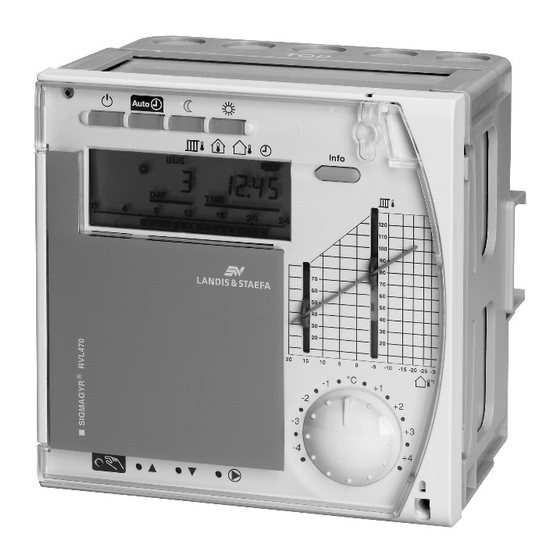
12 Slider for flow temperature setpoint at an outside temperature of 15 °C 13 Setting knob for room temperature readjustments 14 Fixing screw with sealing facility CE1P2522E / 30.03.2000 Basic Documentation RVL470 Siemens Building Technologies 60/68 Handling Landis & Staefa Division... -
Page 69: Display
One button for the activation of manual operation. An LED indicates manual opera- tion. Manual operation is quit by pressing the same button again or by pressing any of the operating mode buttons Siemens Building Technologies Basic Documentation RVL470 CE1P2522E / 30.03.2000 Landis & Staefa Division Handling... -
Page 70: Display Of Positioning Commands
Selection of the next higher block: Keep button depressed and press keep button Selection of the next lower block: Keep button depressed and press keep button CE1P2522E / 30.03.2000 Basic Documentation RVL470 Siemens Building Technologies 62/68 Handling Landis & Staefa Division... -
Page 71: Info Button
19.2. Commissioning 19.2.1. Installation instructions The RVL470 is supplied with installation instructions which give a detailed description of installation, wiring and commissioning with functional checks and settings. They are written for trained specialists. Each operating line has an empty field in which the se- lected value can be entered. -
Page 72: Setting The Other Operating Lines
In the control panel front • In the sloping front of a control desk 19.3.2. Mounting choices The RVL470 can be mounted in three different ways: • Wall mounting: the base is secured to a flat wall with three screws •... -
Page 73: Engineering
Y2/K5 Heating circuit mixing valve CLOSE / second burner stage ON Input for Q1 Heating circuit pump / circulating pump The mains voltage side carries two auxiliary terminals (N and Siemens Building Technologies Basic Documentation RVL470 CE1P2522E / 30.03.2000 Landis & Staefa Division Engineering 65/68... -
Page 74: Connection Diagrams
Heating circuit pump/circulating pump Controller RVL470 Remote operation "Operating mode" Remote operation “Flow temperature setpoint” Actuator for three-position control Wire link for locking the district heat parameters CE1P2522E / 30.03.2000 Basic Documentation RVL470 Siemens Building Technologies 66/68 Engineering Landis & Staefa Division... -
Page 75: Mechanical Design
21. Mechanical design 21.1. Basic design The RVL470 is comprised of controller insert, which accommodates the electronics, the power section, the output relays and – on the front – all operating elements, and the base, which carries the connection terminals. The operating elements are located be- hind a lockable transparent cover. -
Page 76: Technical Data
0...50 °C Operation Weight (net) 1.1 kg For setting ranges, refer to the description of the individual function blocks and individ- ual operating lines. CE1P2522E / 30.03.2000 Basic Documentation RVL470 Siemens Building Technologies 68/68 Technical data Landis & Staefa Division... - Page 77 H-contacts Siemens Building Technologies Basic Documentation RVL470 CE1P2522E / 30.03.2000 Landis & Staefa Division Index INDEX-1...
- Page 78 CE1P2522E / 30.03.2000 Basic Documentation RVL470 Siemens Building Technologies INDEX-2 Index Landis & Staefa Division...
- Page 79 / summertime changeover switching times wintertime terminate the relay test yearly clock terminate the simulation Y min function Siemens Building Technologies Basic Documentation RVL470 CE1P2522E / 30.03.2000 Landis & Staefa Division Index INDEX-3...
- Page 80 Heating limit for REDUCED heating (ECO night) Holiday period 1...8 Hours run counter Identification code of room unit Integral action time of control (Tn) CE1P2522E / 30.03.2000 Basic Documentation RVL470 Siemens Building Technologies INDEX-4 Alphabetical list of operating lines Landis & Staefa Division...
- Page 81 Setpoint for frost protection / holiday mode Setpoint for NORMAL heating Setpoint for REDUCED heating Source of the room temperature Summer- / wintertime changeover Switching differential Siemens Building Technologies Basic Documentation RVL470 CE1P2522E / 30.03.2000 Landis & Staefa Division Alphabetical list of operating lines INDEX-5...
- Page 82 Type of heating curve adjustment Type of optimization Waiting time second burner stage Weekday (for input heating program) Weekday Winter- / summertime changeover Year CE1P2522E / 30.03.2000 Basic Documentation RVL470 Siemens Building Technologies INDEX-6 Alphabetical list of operating lines Landis & Staefa Division...
- Page 83 Table modified, resulting from function changes on the controller: addresses G = 1 and S = 0 now permitted with all plant types 17.1.3.3 Name of operating line 178 corrected (clock operation) Siemens Building Technologies Basic Documentation RVL470 CE1P2522E / 30.03.2000 Landis & Staefa Division Corrigenda INDEX-7...
- Page 84 CE1P2522E / 30.03.2000 Basic Documentation RVL470 Siemens Building Technologies INDEX-8 Corrigenda Landis & Staefa Division...