Epson TM-U590 Technical Reference Manual
Hide thumbs
Also See for TM-U590:
- User manual (84 pages) ,
- Operator's manual (56 pages) ,
- Product information manual (4 pages)
Table of Contents
Advertisement
Quick Links
Technical Reference Guide
Product Overview
Describes features and general specifications for the product.
Setup
Describes setup and instrallation of the product and peripherals.
Application Development Information
Describes how to control the printer and necessary information
when you develop applications.
Handling
Describes how to handle the product.
Appendix
Describes interfaces, connectors and character code tables.
M00001501
Rev. A
Advertisement
Table of Contents

Related Manuals for Epson TM-U590


Summary of Contents for Epson TM-U590
-
Page 1: Product Overview
Technical Reference Guide Product Overview Describes features and general specifications for the product. Setup Describes setup and instrallation of the product and peripherals. Application Development Information Describes how to control the printer and necessary information when you develop applications. Handling Describes how to handle the product. -
Page 2: Revision History
• Neither is any liability assumed for damages resulting from the use of the information contained herein. • Neither Seiko Epson Corporation nor its affiliates shall be liable to the purchaser of this product or third parties for damages, losses, costs, or expenses incurred by the purchaser or third parties as a result of: accident, misuse, or abuse of this product or unauthorized modifications, repairs, or alterations to this product, or (excluding the U.S.) failure to strictly comply with Seiko Epson Corporation’s operating... -
Page 3: For Safety
For Safety Key to Symbols The symbols in this manual are identified by their level of importance, as defined below. Read the following carefully before handling the product. You must follow warnings carefully to avoid serious bodily injury. WARNING Provides information that must be observed to prevent damage to the equipment or loss of data. -
Page 4: Warnings
• Shut down your equipment immediately if it produces smoke, a strange odor, or unusual noise. Continued use may lead to fire. Immediately unplug the equipment and contact your dealer or a Seiko Epson service center for advice. • Never attempt to repair this product yourself. Improper repair work can be dangerous. -
Page 5: Cautions
Cautions • Do not connect cables in ways other than those mentioned in this manual. Different connections may cause equipment damage or fire. • Be sure to set this equipment on a firm, stable, horizontal surface. CAUTION The product may break or cause injury if it falls. •... -
Page 6: About This Manual
About this Manual Aim of the Manual This manual was created to provide information on development, design, and installation of POS systems and development and design of printer applications for developers. Manual Content The manual is made up of the following sections: Chapter 1 Product Overview Chapter 2... -
Page 7: Table Of Contents
Contents ■ Revision History ........................2 ■ For Safety..........................3 Key to Symbols ............................3 Warnings ..............................4 Cautions..............................5 ■ Restriction of Use ........................5 ■ About this Manual ........................6 Aim of the Manual..........................6 Manual Content ............................ 6 Product Overview ................11 ■... - Page 8 Setup .....................25 ■ Flow of Setup........................25 ■ Installing the Printer......................25 Important Notes on Installation ......................25 ■ Setting the DIP Switches..................... 26 Setting Procedure..........................26 For Serial Interface..........................27 For Parallel Interface ..........................29 Selecting the BUSY Status ........................30 ■ Connecting the Printer to the Host Computer ..............31 For Serial Interface..........................31 For Parallel Interface ..........................33 ■...
- Page 9 Appendix..................51 ■ Specifications of Interface and Connector ..............51 RS-232C Serial Interface ........................51 IEEE 1284 Parallel Interface ......................... 54 ■ Character Code Tables......................57 Common to All Pages ......................... 57 Page 0 [PC437: USA, Standard Europe] .................... 58 Page 1 (Katakana) ..........................59 Page 2 (PC850: Multilingual) ......................
-
Page 11: Product Overview
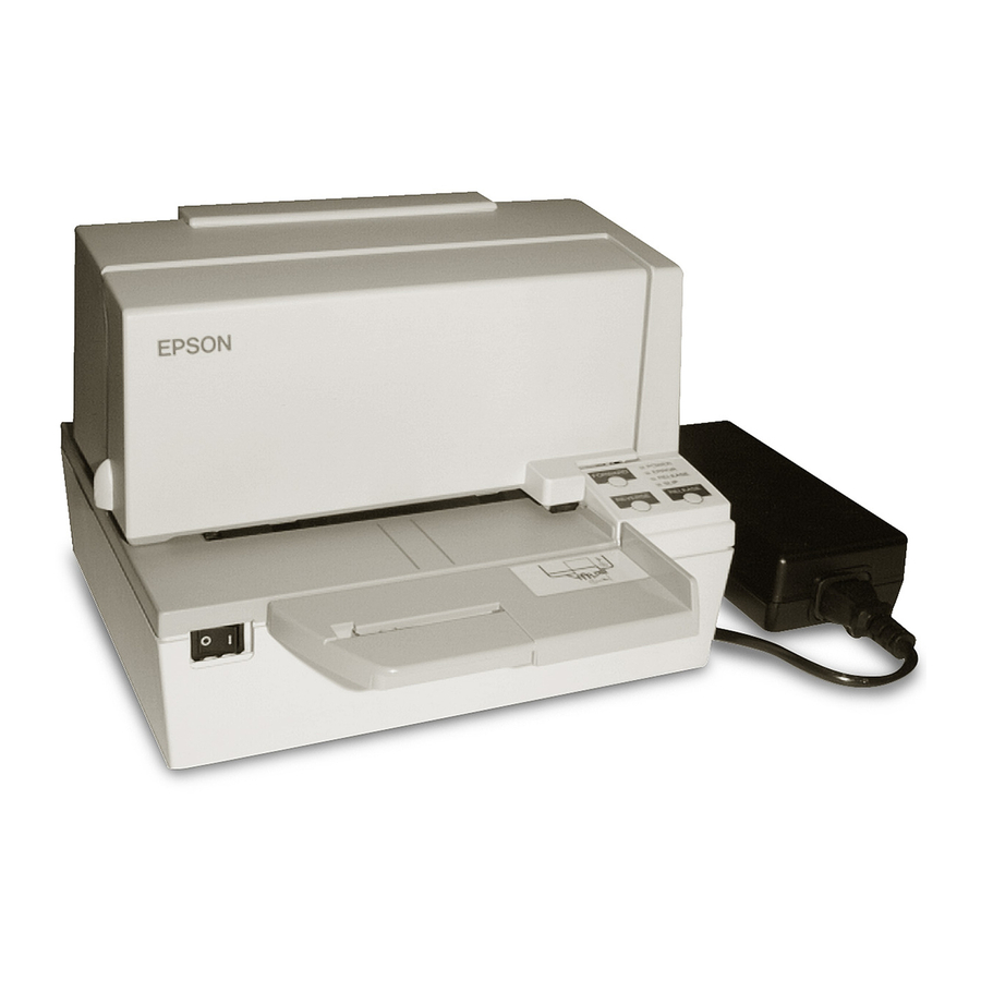
This chapter describes features and specifications of the product. Features The TM-U590 is a POS printer that can print on slip paper. • Copy printing is possible (original + 4 sheets maximum) • Maximum characters per line: 88 with 7 × 9 font. -
Page 12: Part Names And Functions
CAUTION Power Switch Cover Install the power switch cover that comes with the TM-U590 onto the printer to prevent inadvertent changing of the power switch, to prevent tampering, and to improve the appearance of the printer. To reset the printer when the power switch cover is installed, insert a long, thin object (such as the end of a paper clip) into the hole in the power switch cover and press the power switch. -
Page 13: Control Panel
Chapter 1 Product Overview Control Panel (POWER) LED POWER FORWARD FORWARD ERROR LED ERROR FORWARD button RELEASE LED RELEASE SLIP LED SLIP REVERSE REVERSE RELEASE RELEASE REVERSE button RLEASE button Buttons FORWARD button Pressing this button once feeds the slip paper by one line. Holding this button down feeds the slip paper continuously. -
Page 14: Connectors
RELEASE LED (green) • Lights when the slip paper can be inserted. • Flashes during waiting for continuous self-test printing. SLIP LED (green) • Lights during regular operation. • Flashes during waiting for slip insertion/removal. • Goes out when ejecting a slip paper. Connectors All cables are connected to the connector panel on the lower rear of the printer. -
Page 15: Offline
Chapter 1 Product Overview Offline The printer automatically goes offline under the following conditions: • During power on (including resetting with the interface) until the printer is ready • During the self-test • While the front cover is open • While roll paper is fed using the FEED button. •... -
Page 16: Unrecoverable Errors
Unrecoverable Errors Printing is no longer possible when an unrecoverable error occurs. The printer must be repaired. Turn off the power immediately when an unrecoverable error occurs. CAUTION Error LED flash code Error Error description Approx. 160 ms R/W error in memory After R/W checking, the printer does not or gate array work correctly. -
Page 17: Product Specifications
Chapter 1 Product Overview Product Specifications Printing method Serial impact dot matrix Paper Paper feed method Friction feed feed Paper feed pitch Default 4.23 mm {1/6"} 0.176 mm {1/144"} Units can be set by a command. Interface Serial (RS232C), Parallel (IEEE1284) Buffer Receive buffer 4 KB/69 bytes (selectable using the DIP switch 1-2) -
Page 18: Printing Specifications
Printing Specifications Printing method Serial impact dot matrix Head wire configuration 9-pin vertical line, 0.353 mm {1/72"} wire pitch Head wire diameter 0.29 mm {0.01"} Printing direction Bidirectional, minimum distance printing Printing speed Font A 233 cps Font B 311 cps Font C 233 cps Characters per line... -
Page 19: Paper Specifications
Chapter 1 Product Overview Paper Specifications Paper type Normal paper, Carbon copy paper, Pressure sensitive paper Total thickness 009 to 0.36 mm {0.0035 to 0.0141"} Size (W × L) 70 × 70 mm to 210 × 297 mm {2.76 × 2.76" to 8.27 × 11.69"} (A4 size) Paper Normal paper 009 to 0.2 mm {0.0035 to 0.0079"}... - Page 20 • Do not use paper that has holes or is translucent at the BOF position. • Do not use paper that has holes at the TOF sensor position or that has dark positions with low reflection (less than 40% reflection) on the back. 31.0 Form stopper position 18.9...
-
Page 21: Printable Area
Chapter 1 Product Overview Printable Area All the numeric values aa are typical.] The top margin can be set to a minimum of 5 mm {0.19"} by using a command to feed the paper backward. Electrical Characteristics Supply voltage DC24V ± 10% Current Standby Mean: Approximately 0.3A... -
Page 22: Environmental Conditions
[°C] 34 40 45 Ambient temperature Acoustic noise (Operating) Approximately 65 dB (Bystander position) Note) The values above are measured in the Epson evaluation condition. The acoustic noise differs depending on the paper used, printing contents, and print speed. -
Page 23: External Dimensions And Mass
Chapter 1 Product Overview External Dimensions and Mass • Height: Approximately 185 mm {7.28"} • Width: Approximately 252 mm {9.92"} • Depth: Approximately 266 mm {10.47"} (including the document table) • Mass: Approximately 5.0 kg {11.0 lb} <Top view> <Side view>... -
Page 24: Option Specifications
Option Specifications Power Supply Unit (PS-180) [Unit: mm] Electric Input conditions input voltage (rating): 90 to 264VAC characteristics (100VAC -10% to 230VAC +15%) Frequency (rating): 50/60 Hz ± 3 Hz Power consumption (rating): 100VA Output conditions Output voltage (rating): 24VDC ± 5% Output current (rating): 2.0A Output electric power (rating): 48VA Output peak current: 4.5A... -
Page 25: Setup
Chapter 2 Setup Setup This chapter describes setup and installation of the product and peripherals. Flow of Setup This chapter consists of the following sections along with the setup flow of the product and peripherals. Installing the Printer (page 25) Setting the DIP Switches (page 26) Connecting the Printer to the Host Computer (page 31) Connecting the Power Supply Unit (PS-180) (page 34) -
Page 26: Setting The Dip Switches
Setting the DIP Switches On this printer, you can make various settings with DIP switches. The DIP switch functions differ depending on the interface model. Setting Procedure Follow the steps below to change the DIP switch settings. Before you remove the DIP switch cover, turn the printer off. Otherwise, a short-circuit may cause the printer to malfunction. -
Page 27: For Serial Interface
Chapter 2 Setup For Serial Interface DIP Switch Bank 1 Factory Function setting Data reception error Ignored Prints “?” Receive buffer capacity 69 bytes 4 KB Handshaking XON/XOFF DTR/DSR Word length 7 bits 8 bits Parity check Parity selection Even See the “... - Page 28 DIP Switch Bank 2 If you turn on DIP switch 2-7 or 2-8 while the printer power is turned on, the printer may be reset, depending on the signal state. DIP switches should not be changed while the printer power is on. Factory Function setting...
-
Page 29: For Parallel Interface
Chapter 2 Setup For Parallel Interface DIP switch bank 1 Factory Function setting Auto line feed Always enabled Always disabled Receive buffer capacity 69 bytes 4 KB 1-3 ∼ Undefined — — DIP switch bank 2 If you turn on DIP switch 2-7 or 2-8 while the printer power is turned on, the printer may be reset, depending on the signal state. -
Page 30: Selecting The Busy Status
Selecting the BUSY Status With DIP switch 2-1, you can select conditions for invoking a BUSY state as either of the following: • When the receive buffer is full • When the receive buffer is full or the printer is offline In either case above, the printer enters the BUSY state after power is turned on (including resetting with the interface), and when a self-test is being run. -
Page 31: Connecting The Printer To The Host Computer
(DM-D) is to be connected, connect it to the host computer via the serial port. DM-D Serial cable Serial cable Modular cable TM-U590 Cash drawer Pass-through connection This printer is connected to the host computer over the serial interface via a customer display (DM-D). - Page 32 DM-D (Stand type) Modular cable Serial cable Modular cable Cash drawer TM-U590 Connecting the serial interface (RS-232C) cable Be sure to turn off the power supply for both the printer and host computer before connecting the cables. WARNING Insert the interface cable connector firmly into the interface connector on the connector panel.
-
Page 33: For Parallel Interface
(DM-D) is to be connected, connect it to the host computer via the serial port. DM-D Serial cable Modular Parallel cable TM-U590 Cash drawer Connecting the parallel interface cable Insert the interface cable connector firmly into the interface connector on the connector panel. -
Page 34: Connecting The Power Supply Unit (Ps-180)
Connecting the Power Supply Unit (PS-180) Use the PS-180 or an equivalent product as the power supply unit. • Always use the EPSON PS-180 or an equivalent product as the power supply unit. Using a nonstandard power supply can result in electric shock and fire. -
Page 35: Connecting The Cash Drawer
Chapter 2 Setup Connecting the Cash Drawer Use a cash drawer handled by EPSON or your dealer. Connecting the Drawer Kick-out Cable • Specifications of drawers differ depending on makers or models. When you use a drawer other than specified, make sure its specification meets the following conditions. - Page 36 Drawer Circuitry Drawer kick-out connector With shielded Drawer kick-out solenoid Drawer open/close switch Printer side User side [Drawer kick-out side]...
-
Page 37: Application Development Information
Chapter 3 Application Development Information Application Development Information This chapter describes how to control the printer and gives information useful for printer application development. How to Control the Printer Use a driver or ESC/POS commands to control the printer. Selecting a Driver Choose one of the drivers, Advanced Printer Driver (APD) or OPOS ADK, depending on the application operating environment. -
Page 38: Esc/Pos Command
ESC/POS Command ESC/POS is the Epson original printer command system. With ESC/POS commands, you can directly control all the TM printer functions, but detailed knowledge of printer specifications or combination of commands is required compared to using a driver. To use ESC/POS commands, you need to make a nondisclosure contract first and get the ESC/POS Application Programing Guide. - Page 39 Chapter 3 Application Development Information Set right-side character spacing Set all print decoration Turn underline mode on/off Turn emphasized mode on/off Select character font Select character size Turn upside-down print mode on/off Turn 90° clockwise rotation mode on/off Set character decoration Select/cancel user-defined character set Define user-defined characters Cancel print data in page mode...
- Page 40 Commands for bit image Select bit-image mode Define downloaded bit image Print downloaded bit image Commands for status Enable/disable Automatic Status Back (ASB) Transmit status Transmit real-time status Commands for mechanical control Return carriage to home position Commands for sub-functions Initialize printer Transmit printer ID Set horizontal and vertical motion units...
-
Page 41: Software And Manuals
Visual Basic, unlike ordinary Windows drivers. It is not a driver to be used for printing from commercial applications. *2: Describes not Epson’s specific functions, but general information on how to control printers using OPOS ADK (in the chapter “POS Printer”). -
Page 42: Setting Check Modes
Setting Check Modes Besides the ordinary print mode, the printer has a self-test mode and hexadecimal dumping mode to check settings of the printer. Self-test Mode You can confirm the following printer functions by running the self-test. • Control circuit functions •... -
Page 43: Hexadecimal Dumping Mode
Chapter 3 Application Development Information Hexadecimal Dumping Mode In the hexadecimal dumping mode, the printer prints the data transmitted from a host computer in hexadecimal numbers and their corresponding characters. Starting hexadecimal dumping Follow the steps below to perform the hexadecimal dumping. •... -
Page 45: Handling
This chapter describes basic handling of the printer. Installing the Ribbon Cassette Use the EPSON ERC-31 ribbon cassette. The use of any ribbon cassettes other than those approved by EPSON may damage the printer and will void the warranty. Turn the printer on. - Page 46 Inset the ribbon so that the ribbon has no wrinkles or creases and is installed below the print head. Print head Turn the cassette knob 2 or 3 times again to remove any slack. Close the front cover.
-
Page 47: Inserting Slip Paper
Chapter 1 Handling Inserting Slip Paper • Use slip paper that meets the printer specification. For details about paper specification, see "Paper Specifications" on page 19. • Do not use wrinkled or curled paper. Turn the printer on. When the SLIP LED flashes, insert the slip paper, using the right edge of the slip paper inlet as a guide (➀) as far as it will go (➁). -
Page 48: Removing The Paper Guide
Removing the Paper Guide If you use especially wide paper, you may not want to use the paper guide on the document table. You can remove it, as described below. Open the front cover by pulling up the tab on the front cover. Slide the table to the left and remove it. - Page 49 Chapter 1 Handling Turn the document table over, remove the two screws, and remove the plate. Plate Screws Slide the paper guide to the left as shown below to remove it. Paper guide Replace the plate and install the document table and the table.
-
Page 50: Removing Jammed Paper
Removing Jammed Paper Do not touch the print head because it can be very hot after printing. CAUTION Turn off the printer. Open the front cover by pulling up the tab on the front cover. Print head Remove the jammed paper. Close the front cover. -
Page 51: Appendix
Appendix Appendix Specifications of Interface and Connector RS-232C Serial Interface Interface board specifications (RS-232C-compliant) Item Specifications Data transfer method Serial Synchronization Asynchronous Handshake Select one of the following with DIP switch 1-3: • DTR/DSR • XON/XOFF Signal level MARK -3V to -15V logic “1”/OFF SPACE +3V to +15V logic “0”/ON Bit length... -
Page 52: Functions Of Each Connector Pin
Functions of each connector pin Pin no. Signal name Signal direction Function — Frame ground Output Transmission data Input Reception data Output Equivalent to DTR signal (pin 20) Input This signal indicates whether the host computer can receive data. SPACE indicates that the host computer can receive data. - Page 53 Appendix XON/XOFF When XON/XOFF control is selected, the printer transmits the XON or XOFF signals as follows. The transmission timing of XON/XOFF differs, depending on the setting of DIP switch 2-1. DIP switch 2-1 Signal Printer status 1 (ON) 0 (OFF) 1) When the printer goes online after turning on the power (or Transmit Transmit...
-
Page 54: Ieee 1284 Parallel Interface
IEEE 1284 Parallel Interface Modes The IEEE 1284 parallel interface supports the following two modes. Mode Communication direction Other information Host → Printer communication Compatibility mode Centronics-compliant Printer → Host communication Reverse mode Assumes a data transfer from an asynchronous printer Compatibility Mode Compatibility mode allows data transmission from host to printer only: Centronics-compatible. -
Page 55: Interface Signals
Appendix Interface signals Compatibility Source Nibble Mode Byte Mode Mode Host Strobe HostClk HostClk Host/Ptr Data0 (LSB) Data0 (LSB) Data0 (LSB) Host/Ptr Data1 Data1 Data1 Host/Ptr Data2 Data2 Data2 Host/Ptr Data3 Data3 Data3 Host/Ptr Data4 Data4 Data4 Host/Ptr Data5 Data5 Data5 Host/Ptr Data6... - Page 56 Compatibility Source Nibble Mode Byte Mode Mode Host Init Init Init Printer Fault DataAvail/Data0,4 DataAvail Printer DK_STATUS Printer Host SelectIn 1284-Active 1284-Active NC: None Connect ND: Not Defined • A signal name with a rule above it indicates an “L” active signal. •...
-
Page 57: Character Code Tables
Appendix Character Code Tables • The character code tables show only character configurations. They do not show the actual print pattern. • “SP” in the table shows a space. Common to All Pages When International character set (See "International Character Sets" on page 66.) is USA: "... -
Page 58: Pc437: Usa, Standard Europe]
Page 0 [PC437: USA, Standard Europe] Ç É á ░ └ ╨ α ≡ í ü æ ▒ ┴ ╤ β ± Γ é Æ ó ▓ ┬ ╥ ≥ â ô ú │ ├ ╙ π ≤ ä ö ñ... -
Page 59: Katakana)
Appendix Page 1 (Katakana) ┴ ═ ┬ ╞ ┤ ╪ ├ ╡ ¯ ─ │ │ ┌ ♠ ┐ ♥ └ ♦ ┘ ♣ ● ○ ▓ ┼... -
Page 60: Pc850: Multilingual)
Page 2 (PC850: Multilingual) Ç É á ░ └ ð Ó í ü æ ▒ ┴ Ð β ± é Æ ó ▓ ┬ Ê Ô â ô ú │ ├ Ë Ò ¾ ä ö ñ ┤ ─ È õ... -
Page 61: Pc860: Portuguese)
Appendix Page 3 (PC860: Portuguese) Ç É á ░ └ ╨ α ≡ í ü À ▒ ┴ ╤ β ± Γ é È ó ▓ ┬ ╥ ≥ â ô ú │ ├ ╙ π ≤ ã õ ñ ┤... -
Page 62: Pc863: Canadian-French)
Page 4 (PC863: Canadian-French) Ç É ¦ ░ └ ╨ α ≡ ´ ü È ▒ ┴ ╤ β ± Γ é Ê ó ▓ ┬ ╥ ≥ â ô ú │ ├ ╙ π ≤ Â Ë ¨ ┤ ─... -
Page 63: Pc865: Nordic)
Appendix Page 5 (PC865: Nordic) Ç É á ░ └ ╨ α ≡ í ü æ ▒ ┴ ╤ β ± Γ é Æ ó ▓ ┬ ╥ ≥ â ô ú │ ├ ╙ π ≤ ä ö ñ ┤... -
Page 64: Pc858: Euro)
Page 19 (PC858: Euro) Ç É á ░ └ ð Ó í ü æ ▒ ┴ Ð β ± é Æ ó ▓ ┬ Ê Ô â ô ú │ ├ Ë Ò ¾ ä ö ñ ┤ ─ È õ... -
Page 65: Space Page)
Appendix Page 255 (Space Page) In the space page (page 25), the following font is defined as the default. • 7 × 7 font (only when font 7 × 9 is selected. When 9 × 9 font is selected, character codes 80H to FFH are all spaces.) -
Page 66: International Character Sets
International Character Sets ASCII code (Hex) Country France à ° ç § é ù è ¨ Germany § Ä Ö Ü ä ö ü β U.K. £ Denmark I Æ Ø Å æ ø å Sweden ¤ É Ä Ö Å...